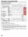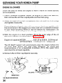
1
The engine exhaust from this product
contains chemicals known to the State
of California to cause cancer, birth
defects or other reproductive harm.
Keep this owner’s manual handy, so you can refer to it at any time.
This owner’s
manual is considered
a permanent
part of the water
pump and should remain with the water pump if resold.
The information
and specifications
included in this publication
were in
effect at the time of approval
for printing.
Honda Motor Co., Ltd.
reserves the right, however, to discontinue
or change specifications
or
design at any time without notice and without incurring any obligation
whatever.
No part of this publication
may be reproduced
without
written permission.
INTRODUCTION
Congratulations
on your selection of a Honda water pump. We are
certain you will be pleased with your purchase of one of the finest
water pumps on the market.
We want to help you get the best results from your new water pump
and to operate it safely. This manual contains the information
on how
to do that; please read it carefully.
As ou read this manual, you will find information
preceded
by a
&iq
symbol. That information
is intended
to help you avoid
damage to your water pump, other property, or the environment.
We suggest you read the warranty
policy to fully understand
its
coverage and your responsibilities of ownership. The warranty policy
is a separate document that should have been given to you by your
dealer.
When your water pump needs scheduled maintenance,
keep in mind
that your Honda servicing
dealer is specially
trained
inservicing
Honda water pumps. Your Honda servicing dealer is dedicated to your
satisfaction
and will be pleased to answer
your questions
and
concerns.
Best Wishes,
Honda Motor Co., Ltd.
1
INTRODUCTION
A FEW WORDS ABOUT SAFETY
Your safety and the safety of others are very important.
water pump safely is an important responsibility.
And using this
To help you make informed decisions about safety, we have provided
operating
procedures
and other information
on labels and in this
manual. This information
alerts you to potential
hazards that could
hurt you or others.
Of course, it is not practical or possible to warn you about all the
hazards associated with operating or maintaining
a water pump. You
must use your own good judgment.
You will
including:
l
l
find
important
Safety Labels -
safety
in a variety
of forms,
on the pump.
Safety Messages - preceded by a safety alert symbol A
of three signal words, DANGER, WARNING, or CAUTION.
These signal words
l
Safety Headings -
l
Safety Section -
l
Instructions
-
and one
mean:
You WILL be KILLED or SERIOUSLY
you don’t.follow
instructions.
HURT if
You CAN be KILLED or SERIOUSLY
you don’t follow instructions.
HURT if
You CAN
instructions.
be
HURT
if
you
don’t
follow
such as IMPORTANTSAFETYINFORMATION.
such as PUMP SAFETY
how to use this pump correctly
This entire book is filled
read it carefully.
2
information
with
important
safety
and safely.
information
-
please
CONTENTS
PUMP SAFETY ...........................................................................................
.................................................
IMPORTANT SAFETY INFORMATION
SAFETY LABEL LOCATIONS .... . ............................................................
5
5
7
CONTROLS & FEATURES .. ... ... .. ... ... .. ... ... .. .... .. ... ... .. ... ... .. ... ...~.................. 8
COMPONENT & CONTROL LOCATIONS . ... .. .... .. .. .... .. .. ...a................... 8
CONTROLS ... ... ... .. .... .. ... ... .. ... ... ... ..... ... ... .. ... ... .. ... ... .. ... ... .. ... ... .. ... ... .. ... ... 9
Fuel Valve Lever ... ... .. ... ... ... .. ... ...... .. ... ... .. ... ... ... ... .. ... ... .. ... .. ... ... ... .. .. ... 9
Ignition Switch .. .. ... ... ... .. ... ... ... .. ... ... .. ... ... .. ... ... ... .. ... ... .. .... .. .. ... ... .. ... .. .. 9
Choke Lever .. ... .. ... ... ... ... ... .. ... ... ... .. ... ... .. ... ... .. ... ... ... .. ... ... .. ... ... .. ... .. ... IO
Throttle Lever ... ... .. ... .... .. .. ... ... ... ... .. ... ... .. ... ... ... .. ... ... .. ... ... .. ... ... .. .. .... . 10
Recoil Starter Grip .. ... ...~~.~..~.......~~............~...............~....................... 11
FEATURES .. .. .... .. ... ... ... .. ... ... ... .. ... ..... ... ... .. .... .. ... ... .. ... .. ... ... .. ... ... .. ... .. ... . 11
Oil Alert@ System .. .... .. ... ... ... .. ... ... .. ... ... .. ... ... .. ... ... .. ... .. ... .. ... ... ... .. .. ... . 11
BEFORE OPERATION ..............................................................................
ARE YOU READY TO GET STARTED? ................................................
IS YOUR PUMP READY TO GO? .........................................................
Check the General Condition of the Pump .....................................
Check the Suction and Discharge Hoses ........................................
Check the Engine ..............................................................................
12
12
13
13
14
14
OPERATION . .. ... ... ... .. ... ... .. ... ... ...~.............................................................
15
SAFE OPERATING PRECAUTIONS ... .. ... ... ... .. ... .. ... ... .. ... .. ... .. ... .. ... .. .. . 15
PUMP PLACEMENT .. .. ... ... ... .. .. .... ..... ... .. ... ... .. ... ... .. ... .. ... .. ... ... .. ... .. .. ... .. 16
. ... .. .. .... .. .. ... ... .. ... ... .. ... .. ... .. ... .. ... .. ... . 17
SUCTION HOSE INSTALLATION
.. .. ... ... .. ... ... .. .. .... .. .. ... .. ... ... .. ... .. .. . 18
DISCHARGE HOSE INSTALLATION
PRIMING THE PUMP ... ... .. .... .. .. ... ...... ... .. .. .... .. .. .... .. .. ... ... .. ... .. ... ... .. .. ... .. 18
STARTING THE ENGINE .. ... ... .. ... ... .. ... .. ... ... ... .. ... .. ... .. ... .. ... .. .. .... .. .. .. ... 19
SETTING ENGINE SPEED ,...................................................................
21
STOPPING THE ENGINE .. .. ... ... .. ..... ... ... .. ... .. ... ... .. .. ... ... .. ... .. ... ... .. .. ... .. . 22
SERVICING YOUR HONDA PUMP . ..... .. ... .. .... .. .. ... ... .. ... ... .. ... .. .. .... .. .. ... .. 24
THE IMPORTANCE OF MAINTENANCE . ... .. ... ... .. .. ... ... .. ... .. ... ... .. .. .. ... . 24
MAINTENANCE SAFETY .. ... .. ... ... ..... ... ... .. ... .. ... ... .. ... .. ... .. ... .. ... ... .. .. ... .. 25
MAINTENANCE SCHEDULE .. ... .. .... .. .. ... ... .. ... ... .. ... ... .. ... .. ... .. ... .. ... .. ... . 26
REFUELING . ... ... .. ... ... ... .. ... ... .. ... ... .. ... ... .. ... ... .. ... ... .. ... ... .. ... .. ... .. ... ... .. .. ... 27
. .. ... ..... ... .. .. ... ... .. ... .. .. ... ... .. .. .. ... ... .. ... .. ... . 28
FUEL RECOMMENDATIONS
ENGINE OIL LEVEL CHECK ... .. .. .. ...... .. .. ... .. ... .. ... .. .. ... .. .. .. ... .. .. ... .. .. .. ... . 29
ENGINE OIL CHANGE . ... .. .. ... .. .. ... .. .. ... .. ... .. .. ... .. ... .. .. ... .. .. ... .. .. .. ... .. .. ... .. 30
3
CONTENTS
SERVICING YOUR HONDA PUMP (continued)
...................................................
ENGINE OIL RECOMMENDATIONS
AIR FILTER INSPECTION .....................................................................
AIR FILTER CLEANING ........................................................................
SEDIMENT CUP CLEANING ................................................................
SPARK PLUG SERVICE ........................................................................
................................................................
IDLE SPEED ADJUSTMENT
..........................
SPARK ARRESTER SERVICE (optional equipment)
PUMP CASING CLEANING .................................................................
31
32
33
34
35
37
38
40
STORAGE .................................................................................................
STORAGE PREPARATION ...................................................................
Cleaning ............................................................................................
Fuel ....................................................................................................
Engine Oil ..........................................................................................
STORAGE PRECAUTIONS ..................................................................
REMOVAL FROM STORAGE ...............................................................
41
41
41
42
45
45
46
TRANSPORTING
.. .. ... . ... .. .. .. .. ... .. .. .. ... .. .. .. .. ... .. .. .. ... .. .. ... .. .. .. .. ... .. .. .. ... .. .. ... . 47
TAKING CARE OF UNEXPECTED PROBLEMS ......................................
ENGINE .................................................................................................
Engine Will Not Start .......................................................................
Engine Lacks Power .........................................................................
PUMP ....................................................................................................
No Pump Output ..............................................................................
Low Pump Output ............................................................................
48
48
48
48
49
49
49
.........................................
TECHNICAL & CONSUMER INFORMATION
TECHNICAL INFORMATION ................................................................
Serial Number Location ...................................................................
Carburetor Modification
for High Altitude Operation ...................
Oxygenated
Fuels ............................................................................
...........................................
Emission Control System Information
Air Index ............................................................................................
...................................................................................
Specifications
CONSUMER INFORMATION ...............................................................
..........................................................................
Honda Publications
.........................................................
Warranty Service Information
50
50
50
51
52.
53
55
56
62
62
63
QUICK REFERENCE INFORMATION
4
............................
Inside back cover
PUMP SAFETY
IMPORTANT
SAFETY INFORMATION
Honda WT20X, WT30X, and WT40X pumps are designed to pump only
water that is not intended for human consumption,
and other uses can
result in injury to the operator or damage to the pump and other
property.
Most accidents can be prevented if you follow all instructions
in this
manual and on the pump. The most common hazards are discussed
below, along with the best way to protect yourself and others.
Operator Responsibility
It is the operator’s responsibility
to provide the necessary safeguards
to protect people and property. Know how to stop the pump quickly in
case of emergency.
If you leave the pump for any reason, always turn
the engine off. Understand the use of all controls and connections.
Be sure that anyone
who operates
instruction.
Do not let children operate
pets away from the area of operation.
the pump
receives
proper
the pump. Keep children and
Pump Operation
Pump only water that is not intended
for human consumption.
Pumping flammable
liquids, such as gasoline or fuel oils, can result in
a fire or explosion,
causing
serious
injury.
Pumping
sea water,
beverages,
acids, chemical
solutions,
or any other
liquid
that
promotes corrosion can damage the pump.
Refuel With Care
Gasoline is extremely
flammable,
and gasoline vapor can explode.
Refuel outdoors, in a well-ventilated
area, with the engine stopped and
the pump on a level surface. Do not fill the fuel tank above the fuel
strainer shoulder. Never smoke near gasoline, and keep other flames
and sparks away. Always store gasoline in an approved
container.
Make sure that any spilled fuel has been wiped up before starting the
engine.
5
PUMP SAFETY
Hot Exhaust
The muffler becomes very hot during operation and remains hot for a
while after stopping the engine. Be careful not to touch the muffler
while it is hot. Let the engine cool before transporting
the pump or
storing it indoors.
To prevent fire hazards, keep the pump at least 3 feet (1 meter) away
from building
walls and other equipment
during operation.
Do not
place flammable objects close to the engine.
Carbon Monoxide
Exhaust
exhaust
6
Hazard
gas contains poisonous carbon monoxide. Avoid inhalation of
gas. Never run the engine in a closed garage or confined area.
PUMP SAFETY
SAFETY LABEL LOCATIONS
The labels shown here contain important
safety information.
Please
read them carefully. These labels are considered
permanent
parts of
your pump. If a label comes off or becomes hard to read, contact an
authorized Honda servicing dealer for a replacement.
\~ETERSO~AL
PUMP CAUTION
INJURY.
J
LABEL
PRECAUTION!
NC FAITE PAS FON-
7
CONTROLS & FEATURES
COMPONENT
& CONTROL LOCATIONS
<wT2ox>
FUEL FILLER CAP
PRIMING/WATER
FILLER CAP
AIR CLEANER
THROTTLE LEVER
CHOKE LEVER
‘DISCHAR,GE
PORT
FUEL VALVE L
CASE DRAIN PIJJG
STARTER GRIP
OIL FlLiER CAP/DIPSTICK
/
IGNITION
SWITCH
PRIMING WATER FILLER CAP
,
SUCTION
MUFFLER
PORT
COVER DRAIN PLUG
t
STRAINER
CONTROLS & FEATURES
CONTROLS
Fuel Valve Lever
The fuel valve opens and closes
the connection
between the fuel
tank and the carburetor.
FUEL VALVE LEVER
The fuel valve lever must be in the
ON position for the engine to run.
When the engine is not in use,
leave the fuel valve lever in the
OFF
position
to
prevent
carburetor flooding and to reduce
the possibility
of fuel leakage.
OFF -I
Ignition Switch
IGNITION SWITCH
The ignition
switch
ignition system.
The ignition
ON position
controls
the
switch must be in the
for the engine to run.
Turning the ignition switch to the
OFF position stops the engine.
9
CONTROLS & FEATURES
Choke Lever
The choke lever opens and closes
the choke valve in the carburetor.
CHOKE LEVER
!
I
The CLOSED position
enriches
the fuel mixture for starting a cold
engine.
The OPEN position
provides
the
correct fuel mixture for operation
after starting, and for restarting a
warm engine.
Throttle
Lever
The throttle
speed.
lever controls engine
Moving
the throttle
lever in the
directions
shown
makes
the
engine run faster or slower.
Pump output
is controlled
by
adjusting
the throttle
lever. At
maximum
throttle
position,
the
pump
will
deliver
the highest
output
volume.
Moving
the
throttle
lever
toward
the idle
position will decrease the output
volume of the pump.
10
\,
i
:.
‘\
\
)
1
i
!
.\
CONTROLS & FEATURES
Recoil Starter Grip
Pulling
the starter grip operates
the recoil starter to crank the engine.
STARTER GRIP
FEATURES
Oil Alert@ System
The Oil Alert@ system is designed to prevent engine damage caused
by an insufficient
amount of oil in the crankcase. Before the oil level in
the crankcase can fall below a safe limit, the Oil Alert@ system will
automatically
stop the engine (the ignition switch will remain in the
ON position).
If the engine stops and will not restart, check the engine
29 ) before troubleshooting
in other areas.
oil level (page
11
BEFORE OPERATION
ARE YOU READY TO GET STARTED?
Your safety is your responsibility.
A little time spent in preparation
significantly
reduce your risk of injury.
will
Knowledge
Read and understand
how to operate them.
this
manual.
Know
what
the controls
Familiarize yourself with the pump and its operation
pumping. Know what to do in case of emergencies.
before you begin
Be sure of what you are pumping.
This pump is designed
only water that is not intended for human consumption.
12
do and
to pump
BEFORE OPERATION
IS YOUR PUMP READY TO GO?
For your safety, and to maximize the service life of your equipment,
it
is very important to take a few moments before you operate the pump
to check its condition.
Be sure to take care of any problem you find, or
have your servicing dealer correct it, before you operate the pump.
Improperly
maintaining
this pump,
or failing to correct a problem
before operation, could cause a
malfunction
in which you could be
seriously injured.
Always perform a preoperation
inspection before each operation,
and correct any problem.
Exhaust gas contains poisonous carbon monoxide. Avoid inhalation of
exhaust gas. Never run the engine in a closed garage or confined area.
To prevent fire hazards, keep the pump at least 3 feet (1 meter) away
from building
walls and other equipment
during operation.
Do not
place flammable objects close to the engine.
Before beginning
your preoperation
level surface and the ignition switch
checks, be sure the pump
is in the OFF position.
is on a
Check the General Condition of the Pump
l
l
l
l
Look around
leaks.
and underneath
the pump for signs
Remove any excessive dirt or debris,
muffler, and recoil starter.
especially
of oil or gasoline
around
the engine
Look for signs of damage.
Check that all nuts, bolts, screws,
tightened.
hose connectors
and clamps
are
13
BEFORE OPERATION
Check the Suction and Discharge Hoses
l
l
l
l
Check the general condition
of the hoses. Be sure the hoses are in
serviceable
condition
before
connecting
them
to the pump.
Remember that the suction hose must be reinforced construction
to
prevent hose collapse.
Check that the sealing washer
good condition (see page 17 ).
in the suction
Check that the hose connectors
(see pages 17& 18).
and clamps
Check that the strainer is in good condition
suction hose (see page 17 ).
hose connector
are securely
and is installed
is in
installed
on the
Check the Engine
l
l
l
Check the oil level (see page 29 ). To avoid the inconvenience
of an
unexpected
shutdown
by the Oil Alert@ system, always check the
engine oil level before startup.
Check the air filter (see page32 ). A dirty air filter will restrict
to the carburetor,
reducing engine and pump performance.
air flow
Check the fuel level (see page 27 ). Starting with a full tank will help
to eliminate or reduce operating interruptions
for refueling.
14
OPERATION
SAFE OPERATING PRECAUTIONS
To safely realize the full potential of this pump, you need a complete
understanding
of its operation and a certain amount of practice with
its controls.
Before operating
the pump for the first time, please review the
IMPORTANT SAFETY INFORMATION on page 5 and the chapter titled
BEFORE OPERA TION.
For your safety, avoid starting or operating the engine in an enclosed
area, such as a garage. Your engine’s exhaust contains
poisonous
carbon monoxide
gas which can collect rapidly in an enclosed area
and cause illness or death.
Pump only water that is not intended
for human
consumption.
Pumping flammable
liquids, such as gasoline or fuel oils, can result in
a fire or explosion,
causing
serious
injury.
Pumping
sea water,
beverages,
acids, chemical
solutions,
or any other
liquid
that
promotes corrosion can damage the pump.
15
OPERATION
PUMP PLACEMENT
For best pump performance,
place the pump near the water level, and
use hoses that are no longer than necessary. That will enable the
pump to produce the greatest output with the least self-priming
time.
As head (pumping
height)
increases,
pump
output
decreases.
Maximum
head specifications
and pump performance
curves are
shown in the tables on pages 57,59 and 61 . The length, type, and size
of the suction and discharge hoses can also significantly
affect pump
output.
Discharge
head capability
capability,
so it is important
total head.
is always
for suction
greater
than suction
head
head to be the shorter part of
Minimizing
suction head (placing the pump near the water level) is
also very important
for reducing self-priming
time. Se/f-priming time
is the time it takes the pump to bring water the distance of the suction
head during initial operation.
TOTAL HEAD
16
OPERATION
SUCTION HOSE INSTALLATION
Use the commercially
available
hose and hose connector
with the
hose clamp provided
with the pump. The suction
hose must be
reinforced with a noncollapsible
wall or braided wire construction.
The suction
hose should
be no longer
than necessary.
Pump
performance
is best when the pump is near the water level, and the
hoses are short.
Use a hose clamp to securely fasten the hose connector
hose in order to prevent air leakage and loss of suction.
hose connector sealing washer is in good condition.
to the suction
Verify that the
Install the strainer (provided with the pump) on the other end of the
suction hose, and secure it with a hose clamp. The strainer will help to
prevent the pump from becoming clogged or damaged by debris.
Securely
tighten
the hose connector
SUCTION PORT
\
on the pump suction
SEA/LING WASHER (commercially
port.
available)
HOSE COUPLER (commercially
m
/SUCTION
HOSE
(commercially
available)
HOSE CLAMP
HOSE CONNECTOR
HOSE CLAMP
available)
OPERATION
DISCHARGE HOSE INSTALLATION
HOSE CONNECTOR
Use a commercially
available
hose with the hose connector and
clamp provided with the pump.
It is best to use a short, largediameter
hose, because that will
reduce fluid friction and improve
pump
performance.
A long or
small-diameter
hose will increase
fluid friction
and reduce pump
output.
Tighten the hose clamp securely
to prevent
the discharge
hose
from disconnecting
under high
pressure.
HOSE CLAMP
PRIMING THE PUMP
Before starting
the engine,
remove the filler cap from the pump
chamber, and completely
fill the pump chamber with water. Reinstall
the filler cap, and tighten it securely.
Operating the pump dry will destroy the pump
been operated dry, stop the engine immediately,
to cool before priming.
PRIMING WATER FILLER CAP
18
seal. If the pump has
and allow the pump
1
OPERATION
/
STARTING THE ENGINE
1. Move the fuel valve lever to the ON position.
FUEL VALVE LEVER
i
i
I
,
i
i
\
2. To start a cold engine,
move the choke lever to the CLOSED position.
To restart a warm engine,
leave the choke lever in the OPEN position.
CHOKE LEVER
3. Move the throttle lever away from the SLOW position,
the way toward the FAST position.
THROl-iLE
about
l/3 of
LEVER
19
!
OPERATION
4. Turn the ignition
\:
switch
5. Pull the starter grip lightly until you feel resistance,
Return the starter grip gently.
STARTER GRIP
20
\-
to the ON position.
then pull briskly,
OPERATION
/
6. If the choke lever was moved to the CLOSED position to start the
engine, gradually move it to the OPEN position as the engine warms
up.
SETTING ENGINE SPEED
After starting the engine, move the throttle
for self-priming,
and check pump output.
lever to the FAST position
Pump output is controlled
by adjusting
engine speed. Moving the
throttle
lever in the FAST direction will increase pump output, and
moving the throttle lever in the SLOW direction will decrease pump
output.
THROTTLE LEVER
,
21
I
OPERATION
\ .’
\
STOPPING THE ENGINE
To stop the engine
the OFF position.
procedure.
in an emergency,
Under
normal
sitiply turn the ignition
conditions,
use the
1. Move the throttle
lever to the SLOW position.
I \
2. Turn the ignition
22
switch
to the OFF position.
switch to
following
THROTTLE LEVER
OPERATION
3. Turn the fuel valve lever to the OFF position.
OFF
’ v-
After use, remove the case and cover drain plugs (see page42),
and
drain the pump chamber. Remove the filler cap, and flush the pump
chamber with clean, fresh water. Allow the water to drain from the
pump chamber, then reinstall the filler cap and drain plug.
23
I
SERVICING YOUR HONQA PUMP
THE IMPORTANCE
OF MAINTENANCE
Good maintenance
is essential for safe, economical,
operation. It will also help reduce air pollution.
and trouble-free
Improperly
maintaining
this pump,
or failure to correct a problem
before operation, can cause a
malfunction
in which you can be
seriously hurt or killed.
Always follow the inspection and
maintenance
recommendations
and
schedules in this owner’s manual.
To help you properly care for your pump, the following
pages include
a maintenance
schedule,
routine inspection
procedures,
and simple
maintenance
procedures
using basic hand tools. Other service tasks
that are more difficult,
or require special tools, are best handled by
professionals
and are normally
performed
by a Honda technician
or
other qualified mechanic.
The maintenance
schedule applies to normal operating conditions.
If
you operate your pump under severe conditions,
such as sustained
high-load
or high-temperature
operation,
or use in unusually
wet or
dusty conditions,
consult your servicing dealer for recommendations
applicable to your individual
needs and use.
Remember that your servicing
dealer knows
fully equipped to maintain and repair it.
your
pump
best and is
To ensure the best quality
and reliability,
use only new,
Honda parts or their equivalents
for repair and replacement.
genuine
Maintenance,
replacement, or repair of emission control devices and
systems may be performed by any engine repair establishment
or
individual, using parts that are “certified” to EPA standards.
24
SERVICING YOUR HONDA PUMP
MAINTENANCE
SAFETY
Some of the most important
safety precautions
follow. However, we
cannot warn you of every conceivable
hazard that can arise in
performing
maintenance.
Only you can decide whether or not you
should perform a given task.
Failure to properly follow
maintenance
instructions
and
precautions can cause you to be
seriously hurt or killed.
Always follow the procedures and
precautions
in the owner’s manual.
Safety Precautions
l
Make sure the engine is off before you begin any maintenance
repairs. This will eliminate several potential hazards:
-Carbon monoxide poisoning from engine exhaust.
Be sure there is adequate ventilation
whenever you operate
engine.
-Burns from hot parts.
Let the engine and exhaust
l
the
system cool before touching.
-Injury from moving parts.
Do not run the engine unless instructed
l
or
to do so.
Read the instructions
before you begin, and make sure you have the
tools and skills required.
To reduce the possibility
of fire or explosion,
be careful when
working
around gasoline.
Use only a nonflammable
solvent, not
gasoline, to clean parts. Keep cigarettes, sparks, and flames away
from all fuel-related
parts.
25
I
SERVICING YOUR HONDA PUiMP
MAINTENANCE
erform
SCHEDULE
at every indicated
month or operating
l
Emission-related
hour
items.
* Replace the paper air filter element only.
(1)
Service more frequently
(2)
These items should be serviced by your servicing dealer, unless you
have the proper tools and are mechanically proficient. Refer to Honda
shop manual for service procedures.
(3)
For commercial
use,
maintenance intervals.
26
when used in dusty areas.
log
hours
of operation
to
determine
proper
SERVICING YOUR HONDA PUMP
REFUELING
Fuel tank capacities
0.95 US gal (3.6 Q ,0.79 Imp gal)
WT20X:
1.59 US gal (6.0 Q , 1.32 Imp gal)
WT30X:
1.72 US gal (6.5 Q , 1.43 Imp gal)
WT40X:
With the engine stopped, remove the fuel tank cap and check the fuel
level. Refill the tank if the fuel level is low.
Gasoline is highly
explosive.
flammable
and
You can be burned or seriously
injured when handling fuel.
l
l
l
Stop the engine and keep heat,
sparks, and flame away.
Handle fuel only outdoors.
Wipe up spills immediately.
27
SERVICING YOUR HONDA PUMP
Refuel in a well-ventilated
area before starting the engine. If the engine
has been running, allow it to cool. Refuel carefully to avoid spilling fuel.
Do not fill the fuel tank above the fuel strainer shoulder. After refueling,
tighten the fuel tank cap securely.
Never refuel the engine inside a building where gasoline fumes may
reach flames or sparks. Keep gasoline away from appliance pilot lights,
barbecues, electric appliances, power tools, etc.
Spilled fuel is not only a fire hazard, it causes environmental
Wipe up spills immediately.
damage.
Fuel can damage paint and plastic, Be careful not to spill fuel when
filling your fuel tank. Damage caused by spilled fuel is not covered
under warranty.
FUEL RECOMMENDATIONS
Use unleaded gasoline with a pump octane rating of 86 or higher.
These engines are certified to operate on unleaded gasoline. Unleaded
gasoline produces fewer engine and spark plug deposits and extends
exhaust system life.
Never use stale or contaminated
gasoline
Avoid getting dirt or water in the fuel tank.
Occasionally
you may hear a light
(metallic rapping noise) while operating
cause for concern.
or an oil/gasoline
“spark
under
mixture.
knock”
or “pinging”
heavy loads. This is no
If spark knock or pinging
occurs at a steady engine speed, under
normal load, change brands of gasoline.
If spark knock or pinging
persists, see an authorized Honda servicing dealer.
Running the engine
engine damage.
with
Running the engine
and the Distributor’s
by misuse.
with persistent spark knock or pinging is misuse,
Limited Warrantydoes
not cover parts damaged
28
persistent
spark knock or pinging
can cause
SERVICING YOUR HONDA PUMP
ENGINE OIL LEVEL CHECK
Check the engine
position.
oil level
with
1. Remove the oil filler cap/dipstick
the engine
stopped
and wipe it clean.
2. Insert and remove the dipstick without screwing
Check the oil level shown on the dipstick.
it into the filler neck.
3. If the oil level is low, fill to the edge of the oil filler
recommended
oil (see page 31).
4. Screw in the oil filler cap/dipstick
and in a level
hole with
the
securely.
OIL FILLER NECK
UPPER LIMIT
OIL FILLER CAP/DIPSTICK
The Oil Alert@ system will automatically
stop the engine before the oil
level falls below safe limits. However, to avoid the inconvenience
of an
unexpected shutdown, check the oil level regularly.
29
SERVICING YOUR HONDA PUMP
ENGINE OIL CHANGE
Drain the used oil while
and completely.
the engine
is warm.
Warm oil drains
quickly
1. Place a suitable container
below the engine to catch the used oil,
then remove the oil filler cap/dipstick and the drain plug.
2.Allow the used oil to drain completely,
and tighten it securely.
then reinstall
the drain plug,
Please dispose of used motor oil in a manner that is compatible with
the environment.
We suggest you take used oil in a sealed container
to your local recycling center or service station for reclamation.
Do
not throw it in the trash ,pour it on the ground, or down a drain.
3.With the engine in a level position, fill to the outer edge of the oil
filler hole with the recommended
oil (see page 31 ).
Engine oil capacity:WT20X . .. .. .. .. ... .. .. 0.63 US qt (0.60 Q , 0.53 Imp qt)
WT30X/WT40X..
1.2 US qt (1 .I Q , 1.O Imp qt)
The Oil Alert@ system will automatically
stop the engine before the
oil level falls
below
the safe limit.
However,
to avoid
the
inconvenience
of an unexpected
shutdown,
fill to the upper limit,
and check the oil level regularly.
4. Screw in the oil filler cap/dipstick
DRAIN PLUG
OIL FILLER CAP/DIPSTICK
securely.
SERVICING YOUR HONDA PUMP
ENGINE OIL RECOMMENDATIONS
Oil is a major factor affecting
performance
4-stroke automotive
detergent oil.
and service
life.
Use
SAE low-30 is recommended
for general use. Other viscosities shown
in the chart may be used when the average temperature
in your area is
within the recommended
range.
SAE Viscosity Grades
TEMP -20
c
-30
20
0
-20 -10
40
0
60
10
80
20
100°F
30 40°C
AMBIENT TEMPERATURE
The SAE oil viscosity and service classification
the oil container.
Honda recommends
that
category SJ oil.
The recommended
“C to 40 T).
operating
are in the API label on
you use API SERVICE
range of this pump is 23 “F to 104 “F (-5
31
I
SERVICING YOUR HONDA PUMP
AIR FILTER INSPECTION
W3OX and
WT4OX type
WT207 type
1. Unscrew
the wing
nut and
remove the air cleaner cover.
Check the air filter to be sure it
is clean and in good condition.
2. If the air filter is dirty, clean it as
described
on page 33. Replace
the air filter if it is damaged.
3. Reinstall the air cleaner cover,
and tighten
the
wing
nut
securely.
CLEANER
COVER
Operating the engine without an air filter, or with a damaged air filter,
will allow dirt to enter the engine, causing rapid engine wear. This type
of damage is not covered by the Distributor’s Limited Warranty.
32
SERVICING YOUR HONDA PUMP
AIR FILTER CLEANING
A dirty air filter will restrict air flow to the carburetor,
performance.
If you operate the pump in very dusty
air filter
more frequently
than specified
in the
SCHEDULE (see page 26 ).
reducing engine
areas, clean the
MAINTENANCE
WTPOX type
WTBOX and
1. Unscrew the wing nut from the
wT4OX type
air cleaner cover, and remove
the air cleaner cover.
2. Unscrew the wing nut from the
air filter, and remove the air
filter.
3. Separate the foam and paper
:.:
air filter elements.
Check both
&:,
filter
elements,
and replace
them
if they
are damaged.
Always
replace the paper air
filter element every year or 300
hours.
Clean
the air filter
elements
if they
are to be
reused.
Paper air filter element: Tap the
filter element several times on a
hard surface to remove dirt, or
blow
compressed
air
[not
exceeding
30 psi (270 kPa, 2.1
kg/cm2)]
through
the filter
element
from the inside out.
Never try to brush
off dirt;
brushing will force dirt into the
fibers.
Foam air filter element: Wash in warm, soapy water, then rinse
thoroughly,
or wash in nonflammable
solvent.
Allow the filter
element to dry thoroughly.
Dip the filter element in clean engine oil,
then squeeze out all excess oil. The engine will smoke when started
if too much oil is left in the filter element.
4. Wipe dirt from the air cleaner base and cover (and silencer
if
applicable), using a moist rag.
5. Place the foam air filter element over the paper air filter element,
and install the assembled
air filter. Be sure the gasket is in place
beneath the filter. Tighten the wing nut securely.
6. Reinstall the air cleaner cover, and tighten the wing nut securely.
33
SERVICING YOUR HONDA PUiVlP
,
SEDIMENT
CUP CLEANING
1. Move the fuel valve lever to the OFF position,
sediment cup and O-ring.
Gasoline is highly
explosive.
flammable
then remove
the fuel
and
You can be burned or seriously
injured when handling fuel.
l
l
l
Stop the engine and keep heat,
sparks, and flame away.
Handle fuel only outdoors.
Wipe up spills immediately.
2. Wash the sediment
dry them thoroughly.
cup and O-ring
3. Place the O-ring in the fuel valve,
Tighten the sediment cup securely.
in nonflammable
and
install
4. Move the fuel valve lever to the ON position,
Replace the O-ring if there is any leakage.
the sediment
and
cup.
and check for leaks.
O-RING
34
solvent,
SERVICING YOUR HONDA PUMP
SPARK PLUG SERVICE
In order to service the spark plug, you will
(commercially
available).
Recommended
Incorrect
spark plug:
need a spark plug wrench
BPRGES (NGK)
W20EPR-U (DENSO)
spark plugs can cause engine damage.
1. Disconnect the spark plug cap, and remove
spark plug area.
2. Remove the spark plug with a 13/16-inch
any dirt from around
the
spark plug wrench.
SPARK PLUG WRENCH
SPARK PLUG CAP
3. Inspect the spark plug. Replace
it if the electrodes are worn, or
if the insulator
is cracked or
chipped. Clean the spark plug
with a wire brush if you are
going to reuse it.
I
0.028-0.031
in
(0.70-0.80mm)
4.Measure
the
spark
plug
electrode
gap with a suitable
gauge.
Correct the gap, if necessary, by
carefully
bending
the side
electrode.
The gap should be:
0.028-0.031
in (0.70-0.80
mm)
35
SERVICING YOUR HONDA PU,MP
5. Install the spark plug carefully,
by hand! to avoid cross-threading.
6.After the spark plug seats, tighten
wrench to compress the washer.
If reinstalling
the used spark
spark plug seats.
If installing
seats.
plug,
a new spark plug, tighten
with
tighten
a 13/‘16-inch
l/8-1/4
l/2 turn
spark
turn
36
after the
after the spark plug
A loose spark plug can overheat and damage the engine.
Over-tightening
the spark plug can damage the threads
cylinder head.
7. Attach the spark plug cap.
plug
in the
SERVICING YOUR HONDA PUMP
IDLE SPEED ADJUSTMENT
1. Start the engine
temperature.
outdoors,
and allow
it to warm
up to operating
Dry operation
will damage the pump seal. Be sure
chamber is filled with water before starting the engine.
2. Move the throttle
3. Turn the throttle
lever to its slowest
the
pump
position.
stop screw to obtain the standard
idle speed.
Standard idle speed: WT20X: 1,400 % rpm
WT30X/WT40X:
1,400 + 150 rpm
THROTTLE STOP SCREW
37
SERVICING YOUR HONDA PUMP
SPARK ARRESTER SERVICE (optional equipment)
Your engine is not factory-equipped
with a spark arrester. In some
areas, it is illegal to operate an engine without a spark arrester. Check
local laws and regulations.
A spark arrester
is available
from
authorized Honda servicing dealers.
The spark
functioning
arrester
must
as designed.
be serviced
If the engine has been running,
muffler to cool before servicing
1. Remove the 5 mm screws
the muffler protector.
every
100 hours
to keep
the muffler will be very hot. Allow
the spark arrester.
from
the muffler
protector,
it
the
and remove
2. Remove the 4 mm screw from the spark arrester, and remove the
spark arrester from the muffler.
WTZOX
5 mm SCREW (4)
MUFFLER PROTECTOR
4 mm SCREW
RK ARRESTER
MUFFLER
38
SERVICING YOUR HONDA PUMP
wT3OX and W4OX
v
5 mm SCREW (4)
MUFFLER PROTECTOR
SPARK ARRESTER
/
5 mm SCREW (211
V-T
\
~
\
‘3nm
SCREW
(2)
WT4OX type
uses two 4 mm
screws.
MUFFLER’
SPARK ARRESTER
3. Use a brush to remove carbon deposits from
screen. Be careful to avoid damaging the screen.
The spark arrester must be free of breaks
spark arrester if it is damaged.
the spark
and holes.
arrester
Replace
the
SPARK ARRESTER SCREEN
4. Install the spark arrester,
muffler
reverse order of disassembly.
protector,
and
muffler
in the
39
I
SERVICING YOUR HONDA PUMP
PUMP CASING CLEANING
After each use, clean the inside of the pump casing using the following
procedure:
Removal:
1. Remove the drain plugs from the pump
drain the water inside.
casing
and pump
cover to
2. Loosen the pump cover knobs and open the pump cover holders.
3. Remove the pump cover and the volute case from the pump casing,
and remove any debris from pump casing and volute case;
Installation:
1. Install the O-rings
O-rings.
on the pump cover, taking
care not to damage
the
2. Install the pump cover on the pump casing, close the cover holders,
and tighten the knobs hand tight. Then, insert a screwdriver
shaft in
the groove in the knobs and finish tightening
the knobs.
3. Install the two drain plugs in the pump cover and pump casing.
4.After tightening
the pump cover knobs, check the pump
pump casing to ensure that there is no water leakage.
cover and
PUMP COVER KNOB
SCREWDRIVER
VER HOLDER
CkE
40
DRAIN PLUG
PUMP COVER
COVER DkAlN PLUG
STORAGE PREPARATION
Proper storage
preparation
is essential
for keeping
your pump
troublefree
and looking good. The following
steps will help to keep
rust and corrosion
from
impairing
your
pump’s
function
and
appearance, and will make the engine easier to start when you use the
pump again.
Cleaning
1. Wash the engine
and pump.
Wash the engine by hand, and be careful to prevent water from
entering the air cleaner or muffler opening. Keep water away from
controls
and all other places that are difficult
to dry, as water
promotes rust.
l
l
Using a garden hose or pressure washing equipment
can force
water into the air cleaner or muffler opening.
Water in the air
cleaner will soak the air filter, and water that passes through the
air filter or muffler can enter the cylinder, causing damage.
Water contacting
a hot engine can cause damage. If the engine
has been running, allow it to cool for at least half an hour before
washing.
2. Wipe dry all accessible
surfaces.
3. Fill the pump chamber with clean, fresh water, start
outdoors,
and let it run until
it reaches
normal
temperature to evaporate any external water.
Dry operation
will damage the pump seal. Be sure
chamber is filled with water before starting the engine.
the engine
operating
the
pump
41
STORAGE
4. Stop the engine,
cool.
and allow
it to
5. Remove the case drain plug and
cover drain plug, and flush the
pump with clean, fresh water.
Allow the water to drain from
the
pump
chamber,
then
reinstall the drain plugs.
6. After the pump is clean and dry,
touch up any damaged
paint,
and coat areas that may rust
with a light film of oil. Lubricate
controls
with. a silicone
spray
lubricant.
COVER DRAIN PLUG
c&s DRAINPLuo
Fuel
Gasoline
will oxidize and deteriorate
in storage. Old gasoline
will
cause hard starting,
and it leaves gum deposits that clog the fuel
system. If the gasoline in your engine deteriorates
during storage, you
may need to have the carburetor
and other fuel system components
serviced or replaced.
The length of time that gasoline can be left in your fuel tank and
carburetor
without
causing functional
problems
will vary with such
factors as gasoline blend, your storage temperatures,
and whether the
fuel tank is partially or completely filled. The air in a partially filled fuel
tank promotes
fuel deterioration.
Very warm storage/temperatures
accelerate fuel deterioration.
Fuel deterioration
problems
may occur
within a few months, or even less if the gasoline was not fresh when
you filled the fuel tank.
The Distributor’s
Limited
Warranty
does not cover fuel system
damage or engine performance
problems
resulting
from neglected
storage preparation.
You can extend fuel storage life by adding a fuel stabilizer that is
formulated
for that purpose,
or you can avoid fuel deterioration
problems by draining the fuel tank and carburetor.
42
STORAGE
\
Adding a Fuel Stabilizer
to Extend Fuel Storage Life
When adding a fuel stabilizer, fill the fuel tank with fresh gasoline. If
only partially
filled, air in the tank will promote fuel deterioration
during storage. If you keep a container of gasoline for refueling,
be
sure that it contains only fresh gasoline.
1. Add fuel stabilizer
following
the manufacturer’s
instructions.
2. After adding a fuel stabilizer, run the engine outdoors for 10 minutes
to be sure that treated gasoline has replaced the untreated gasoline
in the carburetor.
Dry operation
will damage the pump seal. Be sure
chamber is filled with water before starting the engine.
3. Stop the engine,
the
pump
and move the fuel valve lever to the OFF position.
43
I
STORAGE
Draining the Fuel Tank and Carburetor
1. Place an approved gasoline container
a funnel to avoid spilling fuel.
below the carburetor,
2. Remove the carburetor drain bolt and sediment
fuel valve lever to the ON position.
Gasoline is highly
explosive.
flammable
and use
cup, then move the
and
You can be burned or seriously
injured when handling fuel.
l
l
l
Keep heat, sparks, and flame
away.
Handle fuel only outdoors.
Wipe up spills immediately.
DRAIN BOLT
SEDIMENT
3.After all the fuel has drained into the container,
bolt and sediment cup. Tighten them securely.
44
reinstall
CUP
the drain
STORAGE
Engine Oil
1. Change the engine
oil (see page30
1.
2. Remove the spark plug (see page 35 1.
3. Pour a tablespoon
(5- 10 cc) of clean engine oil into the cylinder.
4. Pull the starter grip several times to distribute
5. Reinstall
the oil in the cylinder.
the spark plug.
6. Pull the starter grip slowly until resistance is felt and the notch on
the starter pulley aligns with the hole at the top of the recoil starter
cover. This will close the valves so moisture cannot enter the engine
cylinder. Return the starter grip gently.
<Align notch on pulley
hole at top of cover.
STORAGE PRECAUTIONS
If your pump will be stored with gasoline
in the fuel tank and
carburetor,
it is important
to reduce the hazard of gasoline vapor
ignition. Select a well-ventilated
storage area away from any appliance
that operates with a flame, such as a furnace, water heater, or clothes
dryer. Also avoid any area with a spark-producing
electric motor, or
where power tools are operated.
If possible,
avoid storage areas
promotes rust and corrosion.
with
high
humidity,
because
that
Unless all fuel has been drained from the fuel tank, leave the fuel valve
lever in the OFF position to reduce the possibility
of fuel leakage.
45
I
STORAGE
Place the pump on a level surface. Tilting’can
cause fuel or oil leakage.
With the engine and exhaust system cool, cover the pump to keep out
dust. A hot engine and exhaust
system can ignite or melt some
materials. Do not use sheet plastic as a dust cover. A nonporous
cover
will trap moisture around the pump, promoting
rust and corrosion.
REMOVAL
FROM STORAGE
Check your pump
this manual.
as described
in the BEFORE OPERATION chapter
of
If the fuel was drained during storage preparation,
fill the tank with
fresh gasoline.
If you keep a container
of gasoline for refueling,
be
sure that it contains
only fresh gasoline.
Gasoline
oxidizes
and
deteriorates
over time., causing hard starting.
If the cylinder
was coated with oil during storage
engine may smoke briefly at startup. This is normal.
46
preparation,
the
TRANSPORTING
If the pump has been running, allow the engine to cool for at least 15
minutes
before loading the pump on the transport
vehicle. A hot
engine and exhaust
system can burn you and can ignite some
materials.
Keep the pump level when transporting
to reduce the possibility
fuel leakage. Move the fuel valve lever to the OFF position.
of
47
TAKING CARE OF UNEXPECTED
PROBLEMS
ENGINE
Engine Will Not Start
1. Check control
Fuel valve OFF.
Correction
Move fuel valve lever
Choke open.
to ON position.
Move choke lever to
Ignition switch OFF.
CLOSED position
unless engine is warm.
Turn ignition switch to
Out of fuel.
ON.
Refuel (p. 27 )
Bad fuel; pump stored
without treating or
draining gasoline, or
carburetor (p. 44 1.
Refuel with fresh
Possible Cause
positions.
2. Check fuel.
gasoline (p. 27 ).
refuel with bad
gasoline.
3. Check
engine
oil
level.
4. Remove and inspect
spark plug.
Low oil level caused
Oil
servicing dealer, or
refer to shop manual.
Add oil (p. 29 ).
Alert@ to stop engine.
Spark plug faulty,
Clean, gap, or replace
fouled, or improperly
spark plug (p. 35 1.
gapped.
Spark plug
Dry and reinstall spark
wet
with
fuel (flooded engine).
5. Take engine to an
authorized Honda
Drain fuel tank and
plug. Start engine with
throttle lever in FAST
Fuel filter clogged,
carburetor malfunction,
position.
Replace or repair faulty
components as
ignition malfunction,
necessary.
valves stuck, etc.
Possible Cause
Correction
Clean or replace filter
Engine Lacks Power
1. Check air filter.
Air filter clogged.
2. Check fuel.
Bad fuel; pump stored
Drain fuel tank and
without treating or
carburetor (p. 44 ).
draining gasoline, or
refuel with bad
Refuel with fresh
gasoline (p. 27 1.
(P. 33 1.
gasoline.
3. Take engine to an
authorized Honda
servicing dealer, or
refer to shop manual.
48
Fuel filter clogged,
carburetor malfunction,
Replace or repair faulty
components as
ignition malfunction,
valves stuck, etc.
necessary.
TAKING CARE OF UNEXPECTED PROBLEMS
PUMP
No Pump Output
1. Check pump
chamber.
2. Check suction hose.
Possible Cause
Pump not primed.
Correction
Prime pump (p. 18 )
Hose collapsed, cut or
punctured.
Replace suction hose
Strainer not completely
underwater.
(P. 17 1.
Sink the strainer and
the end of a suction
hose completely
Air leak at connector.
underwater.
Replace sealing washer
if missing or damaged.
Tighten hose connector
and clamp (p. 17 ).
Strainer clogged.
Clean debris from
strainer.
3. Measure suction and
Excessive head.
4. Check engine.
Low Pump Output
1. Check suction hose.
2. Check discharge
hose.
3. Measure suction and
Engine lacks power.
Possible Cause
Hose collapsed,
damaged, too long, or
diameter too small.
Air leak at connector.
See page 48.
Correction
Replace suction hose
(P. 17 ).
Replace sealing washer
if missing or damaged.
Strainer clogged.
Tighten hose connector
and clamp (p. 17 1.
Clean debris from
Hose damaged, too
strainer.
Replace discharge
hose (p. 18 ).
long, or diameter too
small.
Marginal head.
Relocate pump and/or
Engine lacks power.
hoses to reduce head
(p. 16, 57,59,61).
See page 48.
discharge head.
4. Check engine.
Relocate pump and/or
hoses to reduce head
(p. 16, 57, 59,61 ).
discharge head.
49
TECHNICAL
& CONSUMER
jNFORMATION
TECHNICAL INFORMATION
Serial Number Location
SERIAL NUMBER
FRAME SERIAL NUMBER
Record the frame serial number and the engine serial number in the
space below. You will need these serial numbers when ordering parts,
and when making technical or warranty inquiries (see page 63 ).
Engine serial number:
Frame serial number:
50
TECHNICAL & CONSUMER
Carburetor Modification
INFORMATION
for High Altitude Operation
At high altitude, the standard carburetor
air-fuel mixture will be too
rich. Performance will decrease, and fuel consumption
will increase. A
very rich mixture will also foul the spark plug and cause hard starting.
High altitude performance
can be improved by specific modifications
to the carburetor.
If you always operate your pump at altitudes above
5,000 feet (1,500 meters), have your servicing dealer perform this carburetor modification.
Even with carburetor
modification,
engine horsepower
will decrease
about 3.5% for each l,OOO-foot (300-meter) increase in altitude. The
effect of altitude
on horsepower
will be greater than this if no
carburetor modification
is made.
When the carburetor
has been modified for high altitude operation,
the air-fuel mixture will be too lean for low altitude use. Operation at
altitudes below 5,000 feet (1,500 meters) with a modified carburetor
may cause the engine to overheat and result in serious engine damage.
For use at low altitudes,
have your servicing
dealer return the
carburetor to original factory specifications.
51
TECHNICAL & CONSUMER IlilFORMATlON
Oxygenated
Fuels
Some conventional
gasolines
are being blended with alcohol or an
ether compound.
These gasolines
are collectively
referred to as
oxygenated
fuels. To meet clean air standards,
some areas of the
United States and Canada use oxygenated
fuels to help reduce
emissions.
If you use an oxygenated
fuel, be sure it is unleaded
minimum octane rating requirement.
and meets the
Before using an oxygenated
fuel, try to confirm the fuel’s contents.
Some states/provinces
require this information
to be posted on the
pump.
The following
are the EPA-approved
percentages
of oxygenates:
ETHANOL ~
(ethyl or grain alcohol) 10% by volume
You may use gasoline containing
up to 10% ethanol
by volume.
Gasoline
containing
ethanol
may be
marketed under the name “Gasohol”.
MTBE
(methyl tertiary butyl ether) 15% by volume
You may use gasoline containing
up to 15% MTBE by
volume.
METHANOL
~
(methyl or wood alcohol) 5% by volume
You may use gasoline containing
up to 5% methanol
by volume as long as it also contains cosolvents
and
corrosion
inhibitors
to protect
the fuel system.
Gasoline
containing
more than 5% methanol
by
volume
may cause starting
and/or
performance
problems.
It may also damage metal, rubber, and
plastic parts of your fuel system.
If you notice any undesirable
operating symptoms,
station, or switch to another brand of gasoline.
try another
service
Fuel system damage or performance
problems resulting from the use
of an oxygenated
fuel containing
more than the percentages
of
oxygenates
mentioned above are not covered under warranty.
52
TECHNICAL&CONSUMER
INFORMATION
Emission Control System Information
Source of Emissions
The combustion
process
produces
carbon
monoxide,
oxides
of
nitrogen, and hydrocarbons.
Control of hydrocarbons
and oxides of
nitrogen
is very important
because, under certain conditions,
they
react to form photochemical
smog when subjected to sunlight. Carbon
monoxide does not react in the same way, but it is toxic.
Honda utilizes
the emissions
hydrocarbons.
lean carburetor
settings
of carbon
monoxide,
and other
oxides
systems to reduce
of nitrogen,
and
The U.S. and California Clean Air Acts
EPA and California
regulations
require all manufacturers
to furnish
written instructions
describing the operation and maintenance
of emission control systems.
The following
instructions
and procedures must be followed
in order
to keep the emissions
from your Honda engine within the emission
standards.
Tampering and Altering
Tampering
emissions
tampering
l
l
Removal
systems.
with or altering the emission control system may increase
beyond the legal limit. Among those acts that constitute
are:
or alteration
Altering
or defeating
mechanism
to cause
parameters.
of any
part of the intake,
the governor
the engine to
L
linkage
operate
fuel,
or exhaust
or speed-adjusting
outside
its design
53
TECHNICAL & CONSUMER
INFORMATION
Problems That May Affect Emissions
If you are aware of any of the following
inspected and repaired by your servicing
l
Hard starting
l
Rough idle.
l
Misfiring
l
Afterburning
l
Black exhaust
Replacement
or stalling
or backfiring
symptoms,
dealer.
have your engine
after starting.
under load.
(backfiring).
smoke or high fuel consumption.
Parts
The emission control systems on your Honda engine were designed,
built, and certified
to conform
with EPA and California
emission
regulations.
We recommend
the use of genuine
Honda
parts
whenever
you
have maintenance
done.
These
original-design
replacement
parts are manufactured
to the same standards
as the
original parts, so you can be confident of their performance.
The use
of replacement
parts that are ‘not of the original design and quality
may impair the effectiveness
of your emission control system.
A manufacturer
of an aftermarket
part assumes the responsibility
that
the part will
not adversely
affect emission
performance.
The
manufacturer
or rebuilder of the part must certify that use of the part
will not result in a failure of the engine to comply with emission
regulations.
Maintenance
Follow the maintenance
schedule on page 26 . Remember that this
schedule is based on the assumption
that your machine will be used
for its designed
purpose.
Sustained
high-load
or high-temperature
operation,
or use in unusually
wet or dusty conditions,
will require
more frequent service.
54
TECHNICAL & CONSUMER
INFORMATION
Air Index
An Air Index Information
hang tag/label was applied to this engine in
accordance
with the requirements
of the California
Air Resources
Board.
The bar graph is intended to provide
compare the emissions
performance
the Air Index, the less pollution.
you, our customer, the ability to
of available engines. The lower
The durability
description
is intended to provide you with information
relating to the engine’s emission
durability
period. The descriptive
term indicates the useful-life period for the engine’s emission control
system.
See
your
Emission
Control
Warranty
for additional
information.
Descriptive Term
Applicable to Emissions Durability Period
Moderate
50 hours (0 - 65 cc)
125 hours (greater than 65 cc)
Intermediate
125 hours (0 - 65 cc)
250 hours (greater than 65 cc)
Extended
300 hours (0 - 65 cc)
500 hours (greater than 65 cc)
,
The Air Index Information
hang tag must remain on the pump until it is
sold. Remove the hang tag before operating the pump.
55
/
TECHNICAL & CONSUMER
INFORMATION
Specifications
WTPOX
Dimensions
and weight
Length
Width
Height
Dry weight
24.4 in (620 mm)
17.1 in (435 mm)
15.9 in (405 mm)
84 Ibs (38 kg)
Engine design and performance
1 Model
Engine type
Displacement
[bore X stroke]
Maximum output
Maximum
torque
Cooling system
Ignition system
PTO shaft rotation
1 GXIGOKI
4-stroke, overhead valve, single cylinder
9.9 cu-in (163 cm3)
[2.7 X 1.8 in (68 X 45 mm)]
5.5 PS (4.0 kW) at 4,000 rpm
8.0
Ibf.ft
(11 N.m,
1.1 kgf.m)
at 2,500
rpm
Forced air
Transistorized magneto
Counterclockwise
Tuneup
1 Spark plug gap
Idle speed
Valve clearance
(cold)
Other specifications
56
1 0.028-0.031
in
1
(0.70-0.80
mm)
1,400 %g rpm
Intake:
0.15 f 0.02 mm
Exhaust: 0.20 + 0.02 mm
No other adjustments needed.
See page 35.
See page 37.
See shop
manual..
TECHNICAL & CONSUMER
INFORMATION
WTZOX (continued)
‘ump
Suction port diameter
Discharge port diameter
Total head (maximum)
Suction head (maximum)
Discharge capacity (maximum)
2.0 in (50 mm)
2.0 in (50 mm)
85.3 ft (26 m)
26.2 ft (8 m)
171.7 US gal (650 !2, 143.0 Imp gal)
per minute
50 seconds at 16.4 ft (5 m)
Approximately
2-l/2 hours (actual
time varies with pump load)
Self-priming time
Continuous running time
Pump performance curve
As total head increases,
discharge
capacity decreases.
The following
graph shows the relationship
between
pump discharge
capacity and
total head, while pumping clear water at sea level.
9a-
0
200
52.8
400
105.7
600
158.5
800
211.4
1000
264.2
1200
317.0
1400
369.9
(Wmin)
(US gal/min)
DISCHARGE CAPACITY
57
TECHNICAL & CONSUMER
IljJFORMATION
ingine design and performance
Model
Engine type
Displacement
[bore X stroke]
Maximum output
Maximum torque
Coolina svstem
Ignition system
PTO shaft rotation
1 GX240Kl
1 4-stroke, overhead valve, single cylinder
1 14.8 cu-in (242 cm3)
12.9 X 2.3 in (73 X 58 mm)]
8 PS (5.9 kW) at 3,600 rpm
12.3 Ibfaft (16.7 N.m, 1.7 kgf.m) at 2,500 rpm
I Forced air
1 Transistorized magneto
1 Counterclockwise
Tuneup
Spark plug gap
Idle speed
Valve clearance
(cold)
Other specifications
58
0.028 - 0.031 in
(0.70-0.80
mm)
1,400 f 150 rpm
Intake:
0.15 31 0.02 mm
Exhaust: 0.20 ?I 0.02 mm
No other adjustments needed.
See page 35.
See page 37.
See shop
manual.
I
TECHNICAL & CONSUMER
W3OX
INFORMATION
(continued)
art diameter
Discharge port diameter
Total head (maximum)
Suction head (maximum)
Icharge
capacity (maximum)
Self-priming time
Continuous running time
I
1 3.1 in (80 mm)
3.1 in i80 mm)
98.4 ft (30 m)
26.2 ft (8 m)
1 343.5 US gi 31 (1,300 Q , 286.0 Imp
gal) per minute
50 seconds at 16.4 ft (5 m)
Approximately
2-l/2 houn ; (actual
1
Pump performance
I.--_
..-...--
rime
.
vanes
A
wwi
-..--
purr~p
-^
wad)
curve
As total head increases, discharge capacity decreases. The following
graph shows the relationship
between pump discharge capacity and
total head, while pumping clear water at sea level.
(fit)
(ml
131.
40
98.
30
20
10
I
I
I
I
I
I
200
52.8
400
105.7
600
158.5
800
211.4
1000
264.2
1200
317.0
1400
369.9
I
I
I
I
I
I
I
:
0
(Wmin)
(US gallmin)
DISCHARGE CAPACITY
59
TECHNICAL & CONSUMER
INFORMATION
wT4ox
Dimensions
and weight
Length
Width
Height
1 Dry weight
28.1 in (715 mm)
19.1 in (485 mm)
22.0 in (560 mm)
150 Ibs (68 kg)
Engine design and performance
1
Model
Engine type
Displacement
b ore X stroke]
Maximum output
Maximum torque
Cooling system
. .
Ignrtion system
--. _
PI U shalt rotation
GX340Kl
4-stroke, overhead valve, single cylinder
20.6 cu-in (338 cm3)
1 13.2 X 2.5 in (82 X 64 mm)1
11 PS (8.1 kW) at 3,600 rpm
17.4 Ibfaft (24 N-m, 2.4 kgfam) at 2,500 rpm
Forced air
1 Transistorized magneto
1 Counterclockwise
Tuneup
1 Spark plug gap
Idle speed
Valve clearance
(cold)
Other specifications
60
1 0.028-0.031
in
I
(0.70-0.80
mm)
1,400 + 150 rpm
Intake:
0.15 21 0.02 mm
Exhaust: 0.20 z!z0.02 mm
No other adjustments needed.
See .paoe
- 35.
See page 37.
See shop
manual.
I
TECHNICAL & CONSUMER
INFORMATION
WT40X (continued)
Pump
Suction port diameter
Discharge port diameter
Total head (maximum)
Suction head (maximum)
Discharge capacity (maximum)
3.9 in (100 mm)
3.9 in (100 mm)
95.1 ft (29 m)
26.2 ft (8 m)
607.7 US gal (2,300 0, 506.0 Imp
gal) per minute
50 seconds at 16.4 ft (5 m)
Approximately
2-l/2 hours (actual
1 time varies with pump load)
Self-priming time
Continuous running time
Pump performance curve
As total head increases,
discharge
capacity decreases.
The following
graph shows the relationship
between
pump discharge
capacity and
total head, while pumping clear water at sea level.
(ft)
(ml
131-
40
98-
30
20
10
0
400
105.7
800
211.4
1200
317.0
1600
422.7
2000
528.4
2400
634.1
I
I
I
I
I
I
2800 (Q/min)
739.8 (US gal/min)
I
DISCHARGE CAPACITY
61
TECHNICAL & CONSUMER
CONSUMER
INFORMATION
INFORMATION
Honda Publications
These
publications
will
give
you
additional
information
for
maintaining
and repairing your pump. You may order them from your
Honda pump dealer.
Shop Manual
This manual covers complete maintenance
and overhaul
It is intended to be used by a skilled technician.
Parts Catalog
This manual
62
provides
complete,
illustrated
parts lists.
procedures.
TECHNICAL & CONSUMER
INFORMATION
Warranty Service Information
Servicing dealership personnel are trained professionals.
They should
be able to answer any question you may have. If you encounter
a
problem that your dealer does not solve to your satisfaction,
please
discuss it with the dealership’s
management.
The Service Manager or
General Manager can help. Almost all problems are solved in this way.
If you are dissatisfied
with the decision
made by the dealership’s
contact
the Honda
Power
Equipment
Customer
management,
Relations Office. You can write:
American Honda Motor Co., Inc.
Power Equipment Division
Customer Relations Office
4900 Marconi Drive
Alpharetta, Georgia 300058847
Or telephone:
(770)497-6400
When you write or call, please give us this information:
l
Model and serial number
l
Name of the dealer who sold the pump to you
l
Name and address of the dealer who services
l
Date of purchase
l
Your name, address,
l
A detailed
description
(see page 50 )
and telephone
your pump
number
of the problem
63
MEMO
64
QUICK REFERENCE INFORMATION
Type
Fuel
Capacity
Type
Engine Oil
Capacity
Type
Spark Plug
Gap
Carburetor
Idle speed
Maintenance
Before each
use
First
20 hours
Subsequent
Unleaded gasoline with a pump
octane rating of 86 or higher
(page 28 )
WT2ox:
0.95 US gal (3.6 0,0.79 Imp gal)
WT3ox:
1.59 US gal (6.0 a, 1.32 Imp gal)
WT4ox:
1.72 US gal (6.5 0 , 1.43 Imp gal)
SAE IOW-30, API SJ, for general
use (paqe 31. )
WTZOX:
0.63 US qt (0.60 I?,,0.53 Imp qt)
WT3oX/WT4ox:
1.2 US qt (1.1 0,l.O Imp qt)
NGK: BPRGES
DENSO: W20EPR-U
0.028-0.031
in (0.70-0.80
mm)
(page 35 )
WT2ox:
1,400 %i rpm
WT3OX/WT4OX: 1,400 f 150 rpm
Check ennine oil level.
Check air>iIter.
Change engine oil.
Refer
to the
maintenance
schedule on page 26.