1
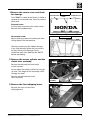
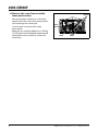
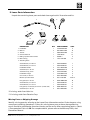
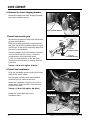
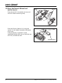
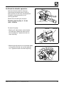
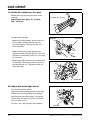
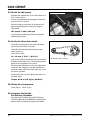
2005 CB900F
SET-UP
INSTRUCTIONS
Set-up and pre-delivery service
must be performed by an authorized
Honda motorcycle dealer.
©2005 American Honda Motor Co., Inc. - All Rights Reserved
MPD 10969 (0501)
Issued: March 2005
IMPORTANCE OF PROPER SET-UP AND PRE-DELIVERY SERVICE
FOR YOUR CUSTOMER'S SAFETY
Proper set-up and pre-delivery service are essential to rider safety and the reliability of the
machine. Any error or oversight made by the technician assembling and servicing a new machine
can result in faulty operation, damage to the machine, or injury to the rider.
WARNING
Improper set-up or pre-delivery service can
create an unsafe condition that can cause
your customer to be seriously hurt or killed.
Follow the procedures and precautions in
this manual and the service manual carefully.
FOR YOUR SAFETY
Some of the most important safety precautions are given below. However, we cannot warn you of
every conceivable hazard that can arise in performing set-up and pre-delivery service. Only you
can decide whether or not you should perform a given task.
WARNING
Failure to properly follow instructions and
precautions can cause you to be seriously
hurt or killed.
Follow the procedures and precautions in this
manual carefully.
IMPORTANT SAFETY PRECAUTIONS
Make sure you have a clear understanding of all basic shop safety practices and that you are
wearing appropriate clothing and safety equipment. When performing the set-up or pre-delivery
service, be especially careful of the following:
• Read the instructions before you begin, and make sure you have the tools and skills required to
perform the tasks safely.
• To prevent the machine from falling on you, park it on a firm, level surface, using the proper
stand(s) to provide firm support.
Make sure the engine is off before you begin any servicing procedures. This will help eliminate
several potential hazards:
• Carbon monoxide poisoning from engine exhaust—be sure there is adequate ventilation
whenever you run the engine.
• Burns from hot parts—let the engine and exhaust system cool before touching.
• Injury from moving parts—do not run the engine unless the instruction tells you to do so.
Even then, keep your hands, fingers, and clothing away.
To reduce the possibility of a fire or explosion, be careful when working around gasoline or
batteries. Use only a nonflammable solvent, not gasoline, to clean parts. Keep all cigarettes,
sparks and flames away from the battery and all fuel-related parts.
©2005 American Honda Motor Co., Inc. - All Rights Reserved
i
2005 CB900F
How To Use This Manual
Follow the complete sequence of steps as shown. Do not short-cut any steps. The sequence has
been established to ensure the unit is properly assembled.
The individual steps are composed of three components:
• Sub-heading—The large sub-headings are a brief description of the step. They are intended
to be used by the experienced technician, one who only needs a brief reminder of the
set-up sequence.
• Descriptive text—The descriptive text explains in detail what is to be done during that step.
This explanation is intended as a guide for the technician needing additional information.
• Photographs/Line art—The photographs or line art support both the sub-headings and the
detailed text.
Indicates the Set-up section
Indicates the Pre-delivery section
Modifications and Accessories
Modifications that you may have made, or should make in the future, to any Honda product, shall
be deemed by our company to have been performed at your sole risk and responsibility, and
without our company's or the manufacturer's approval, or consent, implied or expressed. We
further disclaim any and all liability, obligation, or responsibility for any defects of modified parts
or of the modified product, and for any claims, demands, or causes of action for damage to
property or for personal injuries resulting from the modification of said Honda product.
Torque Table
ii
ITEM
SIZE
TORQUE
Handlebar bolts
8 mm
27 N·m (2.8 kgf·m, 20 lbf-ft)
Handlebar weight
6 mm
10 N·m (1.0 kgf·m, 7 lbf-ft)
Master cylinder holder bolts
6 mm
12 N·m (1.2 kgf·m, 9 lbf-ft)
Clutch lever holder bolts
6 mm
12 N·m (1.2 kgf·m, 9 lbf-ft)
Footpeg socket bolts
8 mm
27 N·m (2.8 kgf·m, 20 lbf-ft)
Rear axle nut
--------
93 N·m (9.5 kgf·m, 69 lbf-ft)
©2005 American Honda Motor Co., Inc. - All Rights Reserved
1. Remove the carton cover and check
for damage.
COVERED CRATE
CARTON COVER
The CB900F is crated at the factory in either a
covered or uncovered crate. You may receive
either one.
STRAP
CARDBOARD TOP
Covered crate:
Cut the strap and remove the carton cover.
Remove the cardboard top.
Uncovered crate:
UNCOVERED CRATE
When stacking, protect the motorcycle from
falling objects and bad weather.
Check the motorcycle for hidden damage.
If you find damage, follow the instructions
on the Delivery and Damage Claims
Guidelines wall chart (Reorder No. S0477)
before proceeding.
2. Remove the master cylinder and the
clutch lever assembly.
BOLTS
Remove the bolt and the front brake
master cylinder.
Do not allow the master cylinder to hang by
its hose. The weight of the assembly could
damage the hose.
Remove the bolt and the clutch
lever assembly.
CLUTCH LEVER
ASSEMBLY
MASTER CYLINDER
3. Remove the front shipping brace.
Remove the nuts and the front
shipping brace.
©2005 American Honda Motor Co., Inc. - All Rights Reserved
NUT
1
2005 CB900F
4. Remove the crate frame and the
loose parts carton.
BOLTS
BRACES
Remove the bolts and braces. Using two
people lift off the crate frame, being careful
not to damage the motorcycle.
Cut the strap and remove the loose
parts carton.
Keep the You and Your Motorcycle - Riding
Tips & Practice Guide booklet separate and
hand-deliver to the customer at the time
of delivery.
2
PARTS
CARTON
STRAP
BOLTS
©2005 American Honda Motor Co., Inc. - All Rights Reserved
5. Loose Parts Information.
Unpack the remaining loose parts and check them against this illustration and list.
2.
1.
4.
3.
7.
5.
6.
DESRIPTION
QTY
PART NUMBER
STEP
1. Handlebar
1
53100-MCZ-000
8
2. Mirrors
2
88210-MCC-000
14
3. Tool kit
1
89010-MCZ-000
15
4. Owner’s Manual
1
31MCZ630*
15
5. Riding Tips & Practice Guide
1
G0045**
4
6. Manual bag
1
77251-342-000
15
Screw/washer, 5 x 20 mm
1
93892-05020-07
7
Screw/washer, 5 x 25 mm
1
93892-05025-07
7
Handlebar Holder
2
53131-MCZ-000
8
7. Attaching Parts:
Socket bolt, 8 x 32 mm
4
96600-08032-10
8
Socket bolt cap, 8 mm
4
91455-KEA-000
8
Handlebar weight
1
53105-MK4-620
9
Oval crew, 6 x 65 mm
1
90191-KBG-000
9
10 & 12
Master cylinder holder
2
45517-166-006
Flange bolt, 6 x 22 mm
2
90101-MBZ-G00
10
Screw/washer, 5 x 45 mm
1
93892-05045-07
11
Screw/washer, 5 x 35 mm
1
93892-05035-07
11
Flange bolt, small head, 6 x 22 mm (clutch side)
2
96001-06022-07
12
Socket bolt, 8 x 22 mm
2
90157-ME9-000
13
*If missing, order from Helm Inc.
**If missing, order from Resolve Corp.
Missing Parts or Shipping Damage
Identify missing parts by referring to the Loose Parts Information section. Order the parts using
normal parts ordering procedures. Claims for missing loose parts or those damaged during
transit should be submitted to American Honda, not the carrier. After completing repairs, submit
a Transportation Claim via iN. For complete details, please refer to the Warranty Policy and
Procedures Manual.
©2005 American Honda Motor Co., Inc. - All Rights Reserved
3
2005 CB900F
6. Remove the front shipping bracket.
BOLTS
Remove the bolts and front shipping bracket
from the handlebar mount.
FRONT SHIPPING BRACKET
7. Install the throttle grip.
PIN
Remove the protective wrap from the throttle
grip/switch assembly.
HOLE
Slide the throttle grip/switch assembly onto
the right side of the handlebar. Move the grip
until the pin in the switch assembly drops into
the hole in the handlebar.
5 x 20 mm
SCREW/WASHER
Close the bottom half of the switch assembly
and secure the halves using a 5 x 20 mm
screw/washer in the front hole and a
5 x 25 mm screw/washer in the rear hole.
Torque the screw/washers, starting with the
front one.
5 x 25 mm
SCREW/WASHER
Torque: 4 N·m (0.4 kgf·m, 3 lbf-ft)
8. Install the handlebars.
HANDLEBAR
Align the handlebar punch mark with the top
edge of the lower holder.
Set the upper holders onto the handlebar
with their punch marks to the front.
Attach the handlebar using four 8 x 32 mm
socket bolts. Torque the four bolts starting
with the front two.
Torque: 27 N·m (2.8 kgf·m, 20 lbf-ft)
PUNCH MARK
Attach the socket bolt caps to the
handlebar bolts.
PUNCH MARK
PUNCH MARK
BOLTS
4
©2005 American Honda Motor Co., Inc. - All Rights Reserved
9. Attach the handlebar weight.
HANDLEBAR WEIGHT
Align the tab on the handlebar weight with
the recess in the handlebar.
Insert the weight into the handlebar and
attach it with a 6 x 65 mm oval head screw.
Torque the screw.
Torque: 10 N·m (1.0 kgf·m, 7 lbf-ft)
10. Install the front brake
master cylinder.
FRONT BRAKE
MASTER CYLINDER
Place the master cylinder assembly on the
handlebar. Align the edge of the assembly
with the punch mark on the handlebar.
Set the master cylinder holder, with its UP
mark facing up, on the assembly.
SWITCH
CONNECTORS
Attach it using two 6 x 22 mm flange bolts.
Torque the two bolts, starting with the
top one.
UP MARK
Torque: 12 N·m (1.2 kgf·m, 9 lbf-ft)
6 x 22 mm
FLANGE BOLTS
Connect the brake light wires to the master
cylinder terminals.
11. Install the turn signal switch.
END CAP
HOLE
Position the switch assembly on the
handlebar by inserting its pin into the hole in
the handlebar and aligning the end cap with
the groove in the switch assembly.
Attach the switch assembly using a 5 x 45 mm
screw/washer in the front hole and a
5 x 35 mm screw/washer in the rear hole.
Torque the screw/washers, starting with the
front one.
Torque: 4 N·m (0.4 kgf·m, 3 lbf-ft)
©2005 American Honda Motor Co., Inc. - All Rights Reserved
PIN
5 x 35 mm
SCREW/WASHER
5 x 45 mm
SCREW/WASHER
5
2005 CB900F
12. Install the clutch lever assembly.
PUNCH MARK
Position the clutch lever assembly on the left
side of the handlebar. Loosely attach it using
its holder and two 6 x 22 mm small head
flange bolts. Be sure the holder's UP mark is
facing up.
Align the split between the holder and
lever assembly with the punch mark on
the handlebar.
UP MARK
Torque the two bolts, starting with the top
bolt first.
BOLTS
CONNECTORS
Torque: 12 N·m (1.2 kgf·m, 9 lbf-ft)
Connect the clutch switch connectors to the
switch terminals.
13. Remove the motorcycle from the
crate base.
Route a sling under the steering stem. Be sure
not to trap any cables, hoses or wires
between the sling and the frame.
SLING
Route another sling through the rear wheel.
Attach the slings to a fork lift or similar lifting
device and apply just enough tension to the
slings to support the motorcycle.
Use a spreader board, if needed, to prevent
the sling from rubbing on the rear body.
SLING
6
©2005 American Honda Motor Co., Inc. - All Rights Reserved
13. Remove the motorcycle from the
crate base (cont.).
LEFT SIDE:
RIGHT SIDE:
BRACE
BRACE
Remove the 6 and 8 mm bolts and right crate
shipping brace.
Remove the 6 and 8 mm bolts and left crate
shipping brace.
Discard the bolts.
BOLTS
BOLTS
Install and torque the 8 x 22 mm socket bolts
securing the footpeg brackets.
Torque: 27 N·m (2.8 kgf·m, 20 lbf-ft)
BOLT
Lower the side stand and place the
motorcycle on a level surface.
Remove the slings.
Clean both sides of all the brake discs using
Pro Honda Brake Cleaner or equivalent and a
clean shop towel.
14. Install the mirrors.
RIGHT SIDE SHOWN:
MIRROR
Thread the mirrors into their mounts and
secure them by tightening their lock nuts.
LOCK NUT
15. Store the Owner’s Manual and
tool kit.
SEAT
Insert the ignition key into the seat lock. Turn
the key clockwise to release the seat. Pull the
seat back and off the motorcycle.
KEY
©2005 American Honda Motor Co., Inc. - All Rights Reserved
7
2005 CB900F
15. Store the Owner’s Manual and
tool kit (cont.).
STRAP
TOOL KIT
Place the tool kit in the holder and secure it
with the rubber restraining strap.
Place the Owner's Manual in its bag and
secure it in the holder located on the bottom
of the seat.
BAG
If the pre-delivery inspection is to be
completed directly after set-up, leave the seat
off. If not, reinstall the seat.
OWNER’S MANUAL
8
©2005 American Honda Motor Co., Inc. - All Rights Reserved
16. Check the cables, hoses, and wire harness routing.
CLUTCH CABLE
THROTTLE CABLES
RIGHT HANDLEBAR SWITCH WIRE
LEFT HANDLEBAR SWITCH WIRE
FRONT BRAKE HOSE
NEGATIVE (-)
BATTERY CABLE
POSITIVE (+)
BATTERY CABLE
BATTERY
©2005 American Honda Motor Co., Inc. - All Rights Reserved
9
2005 CB900F
17. Service and install the battery.
Service the battery only if the motorcycle
has been sold or is to be used as a
demonstration vehicle.
Remove the seat (see step 15).
Remove the bolt, then pull back the right side
cover from the motorcycle.
Follow the instructions included on the
battery case and in Service Letter #48.
The battery used in this motorcycle is a
pre-charged, maintenance-free type. The
electrolyte has already been added to
the battery.
Do not connect the motorcycle battery cables
to the battery terminals until the motorcycle is
ready for delivery.
SIDE COVER
BOLT
Place the ignition in the OFF position.
Remove the battery hold-down strap
and battery.
BOLT
POSITIVE (+) CABLE
Remove the protective cap from the positive
(+) battery terminal.
NUT
BATTERY
Slide the battery terminal nut into the battery
positive (+) terminal. Connect the battery
positive (+) cable to the positive (+) battery
terminal, tighten the bolt, coat the terminal
with dielectric grease, then pull the red cover
over the positive terminal.
Set the battery into the battery box. Install the
battery hold-down strap.
Slide the battery terminal nut into the battery
negative (-) terminal. Connect the battery
negative (-) cable to the negative (-) battery
terminal, tighten the bolt, coat the terminal
with dielectric grease, then pull the cover over
the negative terminal.
Reinstall the side cover and seat.
10
STRAP
NUT
BOLT
NEGATIVE (-)
CABLE
©2005 American Honda Motor Co., Inc. - All Rights Reserved
18. Check the throttle operation.
Check the throttle cable for damage.
Check that the throttle returns from all
open positions to the fully closed position
smoothly and automatically in all
steering positions.
Measure the throttle grip free play.
Throttle grip free play: 2 – 4 mm
(1/16 – 3/16 in.)
2 – 4 mm (1/16 – 3/16 in.)
To adjust free play:
LOCK NUT
ADJUSTER
• Make small adjustments at the throttle
grip adjuster. Loosen the lock nut and
turn the adjuster. Tighten the lock nut
after adjusting.
• Make large adjustments at the throttle body
ADJUSTER
end. Loosen the lock nut and the adjuster
nut. Tighten the lock nuts after adjusting.
LOCK NUTS
©2005 American Honda Motor Co., Inc. - All Rights Reserved
11
2005 CB900F
19. Check the clutch lever free play.
Measure the clutch lever free play at the
lever tip.
10 – 20 mm (3/8 – 13/16 in)
Clutch lever free play: 10 - 20 mm
(3/8 - 13/16 in)
To adjust the free play:
LOCK NUT
ADJUSTER
• Make small adjustments at the lever end
of the cable. Loosen the lock nut and
turn the adjuster. Tighten the lock nut
after adjusting.
• Before making any large adjustments,
loosen the lever adjuster lock nut, turn the
adjuster in completely, then turn it out one
or two turns.
• Make large adjustments at the engine end
ADJUSTING NUT
of the cable. Loosen the lock nut and turn
the adjustment nut. Tighten the lock nut
after adjusting.
LOCK NUT
20. Adjust the brake light switch.
Turn on the ignition switch.
Adjust the rear brake light switch so the light
comes on as the brake begins to engage.
Avoid turning the switch body. Turning the
switch body will twist the wires and could
cause a short circuit.
To adjust, turn the adjuster, not the body.
ADJUSTER
12
©2005 American Honda Motor Co., Inc. - All Rights Reserved
21. Check the engine oil.
FILLER CAP
Before starting the engine, remove the antirust coating from the engine and exhaust
system using a mild detergent and water.
Rinse with clean water.
Support the motorcycle in an upright position
on a firm, level surface.
Check the oil inspection window to be sure
the engine has oil.
If no oil is present in the window, remove the
oil filler cap and add the recommended oil to
bring the level up to between the upper and
lower level marks.
UPPER
LEVEL
MARK
LOWER
LEVEL
MARK
• Oil recommendation: Pro Honda GN4
or HP4 (without molybdenum
additives) 4-stroke oil, or an equivalent
motorcycle oil.
• Viscosity (weight): SAE, 10W-40
• API classification: SF or higher. Do not
use oils labeled as energy conserving
on the circular API service label.
• JASO T 903 standard: MA
• Crankcase capacity: 3.5 Liters
(3.7 US Quarts)
Start the engine and let it idle for 3 - 5
minutes, then shut it off. Wait 2 - 3 minutes
and, supporting the motorcycle in an upright
position, check the oil inspection window. The
oil level should be between the upper and
lower level marks. If the level is low, add the
recommended oil as detailed above. Do not
add oil above the upper level mark.
22. Check the coolant level.
Check the coolant level at the reserve tank
located behind the side cover on the left side.
If required, add Pro Honda HP coolant or
an equivalent high quality ethylene glycol
antifreeze containing silicate-free corrosion
inhibitors to restore the level to the
UPPER mark.
UPPER LEVEL
©2005 American Honda Motor Co., Inc. - All Rights Reserved
13
2005 CB900F
23. Check the idle speed.
THROTTLE STOP SCREW
Support the motorcycle on its side stand on a
firm, level surface.
Connect a tachometer to the engine. Place the
transmission in neutral.
Start the engine and warm it to the normal
operating temperature. Verify the engine
idle speed.
Idle speed: 1,200 ± 100 rpm
Use only the throttle stop screw to make idle
speed adjustments.
24. Verify the drive chain slack.
Place the motorcycle on the side stand and
put the transmission in neutral.
Check the drive chain slack midway on the
lower chain run.
Drive chain slack:
30 – 40 mm (1 3/16 – 1 9/16 in.)
Adjust the slack by loosening the axle nut and
the adjustment lock nuts. Turn the adjustment
bolts to set the proper chain slack.
30 – 40 mm (1 3/16 – 1 9/16 in.)
Set the wheel alignment using the alignment
marks on the swingarm and the notches on
the axle holders. Be sure both sides are set to
the same position.
Torque the axle nut and tighten the lock nuts
on both sides.
Torque: 93 N·m (9.5 kgf·m, 69 lbf-ft)
25. Check the tire pressure.
Front: 36 psi
Rear: 41 psi
26. Complete the Set-Up/
Pre-Delivery Checklist.
Complete an On-Road Set-Up/Pre-Delivery
Checklist (Reorder No. S0299) by checking the
boxes confirming that the steps were done.
14
©2005 American Honda Motor Co., Inc. - All Rights Reserved
1
2
3
4
5
6
COLOR R/Bl
LOCK
OFF
ON
R
Bu/O
IG BAT1 DIODE
G
Bl/Br
G
O
MINI
COLOR
Lb
O
Gr Lb/W O/W
5
9P
G
O/W
Lb/W
Lb
O
CLUTCH
SWITCH
Bl
Bl
Hi
Lo
COLOR Bu/W W
HL
Bu
Hi
DIMMER SWITCH
(N)
KEY ON
Gr
PL
L
PR
3P Bl
O/W
N
P
G
G
Lb/W
Lb
O
KEY OFF
L
4
KEY OFF
LOCK PIN
R
TURN SIGNAL SWITCH
W
3
TURN
SIGNAL
RELAY
G
Bu
Lo
O/W
G
O
G
W
Bu
2
Bu/R
R
KEY
IGNITION SWITCH
LEFT FRONT
TURN SIGNAL LIGHT
12V23/8W
HEADLIGHT
12V60/55W
(LO)
(HI)
Lb/W
G
Lb
P/G
R/G
RIGHT FRONT
TURN SIGNAL LIGHT
12V23/8W
TRIPMETER/ODOMETER
HIGH BEAM INDICATOR
NEUTRAL INDICATOR
OIL PRESSURE INDICATOR
FI INDICATOR
FUEL RESERVE INDICATOR
LCD
DISPLAY
Lg/R
W/G
Gr
SPEEDO
METER
6
MINI
HORN
Bl
Bl
Bl
COOLANT
TEMPERATURE
GAUGE
6P
MINI
NAT
6P
MINI
Bu
6P
COLOR
PUSH
FREE
Lg Bl/Br
Ho BAT3
HORN
SWITCH
COLOR
RUN
OFF
Bl
W/Bl
IG BAT2
ENGINE STOP
SWITCH
TURN SIGNAL DIMMER HORN
POSITION SWITCH
P
ENGINE
STOP
RELAY
Bl
MINI
G
4P
NAT
4P
HEADLIGHTS, PASS.
TURN, STOP
STARTER, BANK ANGLE SENSOR
10A
10A
10A
10A
Bl/R
W/G
W/Bl
Bl/Br
ST
Bl
Bl/R Bu/W
IG BAT4 HL
COLOR W/G W/R
OFF
ON
BAT3 PO
HZ
Gr R/Bu
W
HAZARD SWITCH
METER, IND, HORN, TAIL, (PO), LICENSE
FAN MOTOR, ODOMETER
20A
FUSE
20A
FI IGN, PUMP
CLUTCH
DIODE
R/G
COLOR Y/R
PUSH
FREE
IGNITION
SWITCH
R/W
FUSE
BANK
ANGLE
SENSOR
Y/G
STARTER SWITCH
MINI
TACHO
METER
BAT4
Bl/R
9P
HL
MINI
BAT2
W/Bl
Br
Lg
Bl
NEUTRAL
SWITCH
MINI
2P Bu
DOWN
UP
MINI 2P G
PRESSURE
SWITCH
/),
IGNITION
COILS
1-4
FRONT BRAKE
LIGHT SWITCH
SIDE STAND
SWITCH
W/G
G/Y
ECT
SENSOR
MINI 2P NAT
2-3
FAN
FAN MOTOR
REAR
BRAKE
LIGHT
SWITCH
2P Bl
MINI
FUEL
REVERSE
SENSOR
Bl/Bu
Bl
3P NAT
6%()#,%
SPEED
SENSOR
FAN
MOTOR
RELAY
FUEL
PUMP
FUEL
CUT
RELAY
0/3)4)/.
3%.3/2
CAM
2P
Bl/Bu
G
3P W
ALTERNATOR
G/Bu
Bl/W
Bl/Bu
R/G
Br
G
Br/Bl
Br/Bl
Bl/W
Bl/W
Br
4P
NAT
REGULATOR/
RECTIFIER
MINI
3P Bl
IG
Bl
R/Y
P/Bl
P/Bu
Br
STARTER
MOTOR
4P
BATTERY
12V 10AH
G/Bu
O/Bl
Y/G
Bu/Y
G/P
G/O
FUSE MAIN (A) 30A
Y/Bl
Br/Bl
Y/Bl
W/Bu
Y/Bu
G/P
G
P/G
P/Y
G
STARTER RELAY
SWITCH
MINI
Y
W/Y
IG
ECM
22P Bl
1
2
3
4
5
6
7
8
9
10
11
12
13
14
15
16
17
18
19
20
21
22
A
B
2P R
Y/R
Bl/W
SERVICE
CHECK
CONNECTOR
IGNITION
PULSE
GENERATOR
R/Y
G/R
Gr
W/Y
P/W
1
Br/Bl
Bl/Br
PR
Lb/W
W/Bl
O/W
PL
L
W/Bu
G
P/G
Lg/R
Br/Bl
Bl/Br
G
P/G
Lg/R
Br/Bl
Bl/Br
G/Bu
G/Bl
Y/G
G/Bu
G/Bl
Y/G
W
O
Gr
Lb
R
Gr/Bu
Lg/Y
ENGINE
STOP
SWITCH
22P Light Gray
P
STARTER
SWITCH
P/G
ILLUMINATION
12V1.7Wx2
G/Bl
1
2
3
4
5
6
7
8
9
10
11
12
13
14
15
16
17
18
19
20
21
22
G/W
Y
RIGHT TURN
SIGNAL
INDICATOR
12V1.7W
Hi
Y/R
Bu/W
Y/R
Bu/W
Y/R
Bl/R
Bl/R
G
Lb
Lo
Vz
Bl/Bu
ST
Bu/W
W/G
W/Bl
G/Y
Bl
W/G
W/Bl
G/Y
Bl
G/Bu
O
R/G
Lb
Bu
Bu/R
W/Bu
W
HL
R/W
W
G
R/O
W/Bl
G
IG
BAT1
R/Bl
R
Bu/O
R/Bl
R
Bu/O
P
Bl
Bu/Y
LEFT TURN
SIGNAL
INDICATOR
12V1.7W
Bl/Br
Lg
O
R/G
Lb
Bu
Bu/R
W/Bu
Bu
Bu/W
Bl/Br
Bl
Bu/W
Bl/Br
Lg
Bu/W
Ho
G
G/W
G
G/W
R/Bl
R
Lg/R
Lg
G/R
Bl/R
Bl/Br
W/G
W/Bl
R/G
R/W
R/Y
R
R/Bl
G/W
G/Bu
P/W
G/O
G
Bl/Br
R/W
Bl/W
Bl
R/O
W/G
Gr
W/Bl
Gr
G
G/R
Bu
G/W
O
Lb
G
Bl
Bu
Bl
O
Lb
BAT3
G
Lg
Bu/R
Bu/R
Bl/W
W/G
G/Y
Bl
Bl
Gr
W/Y
Bl/Br
G/Bl
P/G
Bl
G
P
Bl
MINI
3P
Y
Y
Y
Bl/W
P/Y
P/Bu
Bl/W
P/G
Y/R
G/O
R/Y
WPC
G/Y
G
Bl/Br
G
Bl/Br
O
Lb
Bl/W
P/Y
P/Bu
Bl/W
P/G
Y/R
G/O
R/Y
MINI
3P NAT
G/Y
G
Br
Bl
Y
Bu
G
R
W
G
O
G
Bl/Br
Lb
G
2P
Y/R
G/O
R/Y
Bl/W
P/Bl
Bl/W
P/G
Bl/W
P/Bu
Bl/W
P/Y
Bl/W
O/Bl
Bl/W
Y/Bl
Y/Bl
Bl/W
2P NAT
G/Y
G
Br
G/Y
G
Br
G
O
G
Bl/Br
Lb
G
Y/R
Lg/Y
G/O
Br
O
Lb
Lg
P
Gr
LEFT REAR
TURN SIGNAL LIGHT
12V23W
LICENSE LIGHT
12V5W
RIGHT REAR
TURN SIGNAL LIGHT
12V23W
MAP
SENSOR
IAT
SENSOR
TP
SENSOR
BROWN
ORANGE
LIGHT BLUE
LIGHT GREEN
PINK
GRAY
BRAKE AND TAILLIGHTS
12V21W/5Wx2
INJECTOR 4
Bl
INJECTOR 3
Gr/Bu
G/O
INJECTOR 2
EXHAUST AIR INJECT
SOLENOID VALVE
Bl/W
O/Bl
INTAKE AIRDUCT CONTROL
SOLENOID VALVE
Bl/W
Y/Bl
PURGE
CONTROL
SOLENOID
VALVE
(0030Z-MCZ-L100)
INJECTOR 1
2P Bl
BLACK
YELLOW
BLUE
GREEN
RED
WHITE
2P
2P
WPC
2P Bl
WPC
Wiring Diagram
G/Bl
G/P
G/P
G
Y
Y
Y
Y
Y
Y
G
Br
G
R/Y
R
G/R
Y/R
G
G
R
R
©2005 American Honda Motor Co., Inc. - All Rights Reserved
G
G
R
R
2P
Y/R
G/R
R
2P
Y
W/Y
Gr
8P
WPC
2P
MINI
2P
15
G
Bl/W
Y/Bu