1
22. FUEL INJECTION SYSTEM
UXV 500i
13
__________________________________________________________________________________
__________________________________________________________________________________
FUEL INJECTION SYSTEM
__________________________________________________________________________________
SERVICE INFORMATION------------------------------------------------ 22- 1
SPECIFICATIONS ---------------------------------------------------------- 22- 2
INJECTION SYSTEM DIAGRAM --------------------------------------- 22- 3
PARTS LOCATION -------------------------------------------------------- 22- 4
TROUBLESHOOTING----------------------------------------------------- 22- 8
SELF-DIAGNOSTIC PROCEDURES WITHOUT
DIAGNOSTIC TOOL------------------------------------------------------- 22- 7
EFI SELF-DIAGNOSIS CHECK ENGINE LAMP (CELP) FAILURE
CODES-------------------------------------------------------------------------22- 9
SELF-DIAGNOSIS RESET PROCEDURE ---------------------------- 22-10
CELP FAILURE CODES LIST------------------------------------------- 22-11
TPS/ISC RESET ----------------------------------------------------------- 22-15
FUEL PUMP ---------------------------------------------------------------- 22-16
FUEL PUMP RELAY------------------------------------------------------ 22-18
TILT SWITCH(ROLL SENSOR) ---------------------------------------- 22-19
ELECTRONIC CONTROL UNIT (ECU)------------------------------- 22-20
FUEL INJECTOR ---------------------------------------------------------- 22-22
WTS SENSOR -------------------------------------------------------------- 22-24
THROTTLE BODY/T-MAP SENSOR/ISC/TPS ---------------------- 22-25
DIAGNOSTIC TOOL CONNECTOR ----------------------------------- 22-28
DIAGNOSTIC TOOL OPERATION INSTRUCTIONS -------------- 22-30
22
22-0
22. FUEL INJECTION SYSTEM
UXV500i
SERVICE INFORMATION
GENERAL INSTRUCTIONS
● Scooter services can be done with the engine installed in the frame.
● Be sure to relieve the fuel pressure before fuel pump or fuel hose removal.
● Bending or twisting the control cables will affect operation and could cause the cables to stick or
bind, resulting in loss of vehicle control.
● Work in a fully ventilated area. Smoking or allowing flames or sparks in the work area or where
gasoline is stored can cause a fire or explosion.
● Do not apply the Carburetor Cleaners to the inside of the throttle body, which is coated with
molybdenum.
● Do not snap the throttle valve from fully open to fully close after the throttle cable has been
removed; it may cause incorrect idle speed.
● Do not loosen or tighten the painted bolts and screws of the throttle body. Loosening or tighten
them can cause throttle and idle valve synchronization failure.
● Seal the cylinder head intake ports with tape or a clean towel to prevent dirt and debris from
entering the intake ports after the throttle body has been removed.
● Do not damage the throttle body. It may cause incorrect throttle and idle valve synchronization.
● Do not take the fuel pump on the ground downward.
● Always replace the packing when the fuel pump is removed.
● The electronic fuel injection system is equipped with the self-diagnostic system. If the Check
Engine Lamp “CELP” illuminate while riding, follow the self-diagnostic procedures to solve the
problem.
● A faulty AFI problem is often related to poorly connected or corroded connectors. Check those
connections before proceeding.
● When disassembling the fuel injection parts, note the location of the O-rings. Replace them with
new ones upon reassembly.
● Do not disconnect the battery negative (-) or positive (+) cable while engine is running, it may
cause ECU damage.
● Do not disconnect or connect the ECU connector during the ignition switch “ON”; it may
cause the ECU damage.
22-1
22. FUEL INJECTION SYSTEM
UXV 500i
SPECIFICATIONS
ITEM
Throttle body identification number
Idle speed
Throttle grip free play
Fuel injector resistance (at 20°C/68°F)
Fuel pump resistance Float at full position
(at 20°C/68°F)
Float at empty position
Fuel pump standard pressure (at 80 L/Hr)
At -20°C/-4°F
Water temperature
At 40°C/104°F/20°C
sensor resistance
At 100°C/212°F
T-MAP sensor resistance(20°C)
Inductive ignition coil
Throttle position sensor (TPS) resistance (at
20°C/68°F)
Crank position sensor resistance
Roll sensor voltage
Standard
Over 65° (fall down)
SPECIFICATIONS
PTA1
1400±100 rpm
2~6 mm (1/16~1/4 in)
10.6~15.9Ω
About 101 Ω
About 3 Ω
300±10 kPa (3 Bar)
28.6 KΩ
1.46 KΩ/3.51 KΩ±10%
0.176KΩ
1613~2544Ω(1.2 pin)
Primary: 0.55~0.75Ω
3500~6500Ω (1.2 pin)
96~144Ω
0.4~1.4 V
3.7~4.4 V
22-2
22. FUEL INJECTION SYSTEM
UXV500i
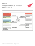
INJECTION SYSTEM DIAGRAM
Key Switch On
FUEL PUMP
CPS
T-MAP SENSOR
TPS
WTS
VOLTAGE
(ECU)
Inductive
Ignition Coil
Fuel Injector
KEY OFF?
YES
END
22-3
ISC
No
Output
Signal
By
ECU
Input
Signal
To
ECU
22. FUEL INJECTION SYSTEM
UXV 500i
PARTS LOCATION
ECU
ECU
Connector
Fuel Injector
T-MAP
Sensor
Inlet Pipe
ISC
TPS
Throttle Body
22-4
22. FUEL INJECTION SYSTEM
UXV500i
Inductive ignition coil
WTS
Air/C
Fuel Pump
Fuel Hose
Fuel Hose
Fuel Pump
22-5
Fuel Pump Coupler
Connector
22. FUEL INJECTION SYSTEM
UXV 500i
Inductive
Ignition
Coil
WTS
Hi Beam Relay
Battery
Lo Beam Start Relay
Relay
22-6
22. FUEL INJECTION SYSTEM
UXV500i
Hazard Control
Winker Relay
REG/REC
Roll Sensor
Switch Power
Relay
Fuel Pump Relay
22-7
22. FUEL INJECTION SYSTEM
UXV 500i
TROUBLESHOOTING
Engine won’t start
• Battery voltage too low
• Fuel level too low
• Pinched or clogged fuel hose
• Faulty fuel pump operating system
• Clogged fuel injector
• Faulty spark plug or wrong type
• Clogged Airflow Bypass Valve
• Wet spark plug
Backfiring or misfiring during acceleration
• Ignition system malfunction
Poor performance (drive ability) and poor
fuel economy
• Pinched or clogged fuel hose
• Faulty fuel injector
Engine stall, hard to start, rough idling
• Intake air leak
• Fuel contaminated/deteriorated
• Pinched or clogged fuel hose
• Idle speed miss adjusted
• Wet spark plug
22-8
13. FUEL INJECTION SYSTEM
UXV500i
CHECK ENGINE LAMP (CELP)
zWhen turning on the switch, the lamp will
be lighted for 2 seconds then off. Let
user to know the lamp is available and
connect to ECU.
z But after then or during riding, if the
CELP start to blink or keep lighting, it
means something wrong with this
vehicle, you better do the further check
to find out the failure code to know
which part get trouble
z
z
z
z
There are 3 kinds of priority grade let
user to know what kind of trouble was
happened.
Priority grade 1: CELP blinks
continuously. This is the most emergent
situation like engine over heat. User
better slow down the riding and go to
dealer for checking.
Priority grade 2: CELP lights all the
time. It means components get trouble
or circuit something wrong. Do the
further check to find out the failure code
to know which part get trouble.
Priority grade 3: CELP just blinks once
suddenly and then disappear. It
sometimes just warning like the RPM
was too high in a short term.
22-9
CELP (Check Engine Lamp)
22. FUEL INJECTION SYSTEM
UXV 500i
How To Show Failure Code
z
z
z
z
z
z
z
z
You can read the failure code by as
below :
Turn switch on. The CELP will be
lighted for 2 seconds then off. The
CELP start to blink to show the failure
codes
(The number of blinks from 1 to 22).
If vehicle got more than one failure
code, the CELP will be shown from
lower number failure code and then
show the other higher number one after
four seconds. All the failure codes
would be shown repeatedly.
How To Reset Failure Code
After repairing the trouble, you should
clear the failure code or it will still exist in
the ECU memory. When you maintain
this vehicle next time, it will show again
and you get confuse.
Turn switch on. The CELP will be lighted
for two seconds then off.
The CELP begins to blink to show the
failure codes.
The self-diagnosis memory data will be
erased when all the failure codes has
showed for 4 cycles.
Example (failure codes 1 and 2):
22-10
13. FUEL INJECTION SYSTEM
UXV500i
CELP FAILURE CODES LIST
Blinks Failure
Codes
Fault description
Engine
overheat
temperature
1
P0217
2
P0335
3
Throttle position sensor
P1120 setting value problem
4
1
Crankshaft position
sensor or circuit
malfunction
P1121 Throttle position sensor
output range problem
22-11
Priority
2
2
2
Fault management
1.Slow down the vehicle and go to workshop for
checking immediately.
2.Confirm if the engine temperature sensor or electric
circuit is abnormality.
1.Check if the connector of crankshaft position sensor
is loosen.
2.Check if the Rotor is align with Crankshaft
position sensor during the crankshaft running.
1.Make sure if the connector of Throttle position
sensor is connected correctly.
2.Check if the Throttle position sensor is adjusted.
1.Make sure if the connector of Throttle position
sensor is connected correctly.
2.Check if the Throttle position sensor is adjusted.
22. FUEL INJECTION SYSTEM
Blinks Failure
Codes
5
Fault description
Throttle position sensor
movement speed
P1122 problem
Priority
2
UXV 500i
Fault management
1.Make sure if the connector of Throttle position
sensor is connected correctly.
2.Check if the Throttle position sensor is adjusted.
6
P0560 Battery voltage
malfunction
1
1. Check if the battery voltage is lower or higher.
2.Check if the charge system is malfunction.
7
P0110 Intake air temperature
circuit malfunction
2
Inlet air temperature sensor or electric circuit
malfunction
P0410 Idle air valve circuit
malfunction
Idle speed volume
control range problem
P0505
2
8
9
10
P0251 Injector or electric
circuit problem
1. Check if the connector of Idle air valve loosen.
2.Check if the resistance of valve is normal.
1.Check if the ISC steps range over 65 steps .
3
2
1.Check if the connector of Injector is loosen.
2.Check if the ECU send signal to Injector.
3.Check if the power source and resistance of Injector
are malfunction.
22-12
13. FUEL INJECTION SYSTEM
Blinks Failure
Codes
Fault description
Priority
Ignition coil or electric
circuit malfunction
11
P0350
12
P0230
2
Fuel pump relay or
electric circuit
malfunction
2
UXV500i
Fault management
1. Check if the connector of ignition coil is loosen.
2. Check if the ECU send signal to Ignition coil.
3. Check if the power source and resistance is
malfunction
1. Check if the connector of relay is loosen.
2. Check if the ECU send signal to relay.
3. Check the fuel pump relay resistance
Check if the belt of CVT is broken.
13
14
15
16
P0219 Engine speed is over
than top speed
2
P1560 Sensor don’t receive
power source from ECU
2
P0700 Engine starting speed
exceed CVT speed
limited
Engine temperature
sensor or electric circuit
P0115
malfunction
2
.Check if ECU output DC5V to sensor.
2. Check if the power source of all sensor is DC5V.
3. Replace a new ECU if the CELP still blinks even the
output power source of ECU is normal.
Don’t use it at present.
2
1. Check if the connector of sensor is loosen.
2. Check if ECU pin is broken.
3.Check if the resistance of sensor is malfunction.
Don’t use it at present.
17
P1561 Temperature gauge
electric circuit
malfunction
22-13
2
22. FUEL INJECTION SYSTEM
Blinks Failure
Codes
18
21
22
Fault description
P0650 CELP electric circuit
malfunction
P0105 Atmospheric Pressure
Sensor/Circuit
Malfunction
Roll sensor or electric
circuit malfunction
P0110
Priority
UXV 500i
Fault management
1. Check if the lamp of CELP is broken.
2. Check if wires of CELP is broken.
3
2
2
1. Check if the connector of sensor is loosen.
2. Check if ECU pin is broken.
3. Check if voltage of sensor is fit in specification.
1. Check if the sensor installation direction is correct.
2. Check if voltage of sensor is fit in specification.
3. Check if ECU pin is broken.
22-14
13. FUEL INJECTION SYSTEM
TPS/ISC RESET
● If close or open the throttle grip randomly,
the ECU may record the incorrect TPS
when the ECU or the throttle body has
been reinstalled. It can cause hard to start
engine or idling speed is not smooth when
engine installation.
● ISC has a motor inside, which controls
ISC valve to obtain smooth idling speed.
The ECU may record the incorrect ISC
position during the engine speed isn’t
working when the ECU or the throttle
body has been reinstalled. It can cause
engine stop, hard to start engine or rough
idling speed.
The throttle position sensor (TPS) and idle
air bypass valve (ISC) have to be reset when
throttle body, T-MAP, TPS, ISC or ECU has
been reinstalled.
TPS/ISC RESET PROCEDURE
Start the engine till engine temperature to
85°C over on idle condition.
ECU will automatic learn engine new
condition.
22-15
UXV500i
22. FUEL INJECTION SYSTEM
UXV 500i
FUEL PUMP
INSPECTIION
F
Put the side stand up and the engine stop
switch is at “RUN”
Disconnect the fuel pump/fuel unit
connector.
Connect the multimeter (+) probe to the Red
terminal and the multi-meter (-) probe to the
Gray terminal.
Turn the ignition switch to “ON” and
measure the voltage between the terminals.
It should be shown the current battery
voltage for a few seconds.
E
If there is still battery voltage, replace the
fuel pump.
If there is not any battery voltage, inspect
the following:
● Fuse
● Fuel pump relay
● ECU
Measure the resistance between the Red(+)
and Black(-) terminals of the fuel pump side
connector.
Standard (at 20°C/68°F): About 10.7 Ω
Fuel level sensor inspection
Measure the resistance between the red
and blue terminals of the fuel pump side
connector.
Standard (at 20°C/68°F):
Float at full position
About101Ω
Float at empty position
About 3 Ω
22-16
13. FUEL INJECTION SYSTEM
REMOVAL
Disconnect the connector and fuel band from
the fuel pump.
Remove the six screws onto the fuel pump.
Remove the fuel pump and O-ring.
UXV500i
Screw
Hose quick band
Fuel Pump Connector
INSTALLATION
Replace a new O-ring on the fuel tank.
Don’t damage the fuel pump wire and
ensure the connector rearward carefully.
Torque: 0.35 kgf-m (3.5 N-m, 2.5 lbf-ft)
FUEL OUTPUT PRESSURE
INSPECTIION
Turn the key to the OFF position.
Use the fuel hose clamp.
Disconnect the fuel hose from the fuel
injector.
Connect the fuel pressure gauge.
Turn the key to the ON position.
Check the fuel pressure.
Standard:3.0 Bar
*
If the fuel output pressure is less than 3.0
bar, may fail to start the engine or in
trouble in case of riding.
22-17
O-ring
22. FUEL INJECTION SYSTEM
UXV 500i
Battery
FUEL PUMP RELAY
INSPECTION
Remove the fuel pump relay.
Connect the ohmmeter to the fuel pump
relay connector terminals.
Connection: R/L-B/R
Connect 12 V battery with the fuel pump
relay connector.
Fuel Pump Relay
Connection: R/Y-O/R
There should be continuity only when 12 V
battery connected.
If there is not continuity when the 12 V
battery is connected, replace a fuel pump
relay.
REMOVAL
Disconnect the fuel pump relay connector
and remove it from frame.
Fuel Pump Relay
22-18
13. FUEL INJECTION SYSTEM
UXV500i
TILT SWITCH(ROLL SENSOR)
INSPECTION
Support the ATV level surface.
Turn the ignition switch to “OFF”
Remove the screws, washers and tilt switch.
* Do
not disconnect the tilt switch
connector during inspection.
Place the tilt switch vertical as shown, and
turn the ignition switch to “ON”.
Measure the voltage between the following
terminals of the tilt switch connector with
the connector connected.
Terminal
Normal
5 V (ECU
V/R (+) -G(-)
voltage)
B/W (+) – G(-)
0.4~1.4 V
Incline the tilt switch 65±10 degrees to the
left or right with the ignition switch turned
to “ON”.
Measure the voltage between the following
terminals of the tilt switch connector with
the connector connected.
Terminal
Normal
5 V (ECU
V/R (+) – G (-)
voltage)
B/W (+) – G(-)
3.7~4.4 V
Roll Sensor
If repeat this test, first turn the ignition
switch to “OFF”, then turn the ignition
switch to “ON”.
REMOVAL/INSTALLATION
Disconnect the connector and remove two
screws.
Remove the Tilt switch.
Installation is in the reverse order of
removal.
* Install the tilt switch with its “UP” mark
facing up.
Tighten the mounting screws securely.
22-19
22. FUEL INJECTION SYSTEM
UXV 500i
ELECTRIC CONTROL UNIT
(ECU)
REMOVAL/INSTALLATION
* ● Do not disconnect or connect the ECU
connector during the ignition switch
“ON”; it may cause the ECU damaged.
● The throttle position sensor (TPS) and
idle air bypass valve (ISC) have to be
reset when throttle body, MAP, TPS,
ISC or ECU has been reinstalled.
ECU Connector
Disconnect the ECU connector and remove
the ECU from the frame.
Installation is in the reverse order of the
removal.
ECU connector remove procedure
(Same as DOWNTOWN 125i)
ECU connector install procedure
(Same as DOWNTOWN 125i)
22-20
13. FUEL INJECTION SYSTEM
INSPECTION
Outlook checking
Checking for ECU pin(1-48) if has damage.
Checking for ECU part number if is correct.
3920A-LKC3-E00 is correct
Voltage inspection
Connect the meter (+) probe to the
B4(R/W)wire and the
meter (-) probe to the M3(G/B) wire to
measure the voltage
MAP content (edition issue no.)
Performance confirmed
22-21
UXV500i
22. FUEL INJECTION SYSTEM
UXV 500i
FUEL INJECTOR
INSPECTION
Disconnect the fuel injector connector.
Measure the resistance between 2 pins of the
fuel injector connector.
Standard: 10.6~15.9 Ω (at 20°C/68°F)
REMOVAL
Disconnect the connector from the fuel
injector.
Remove the bolts of the fuel injector.
Take out of the fuel pipe and fuel injector
from the Inlet pipe.
Remove the fuel injector from the fuel pipe.
Bolt
*
Ensure the fuel pipe without any
pressure, then remove the fuel injector.
STEP 1: Disconnect the fuel pump relay
or fuel pump connector.
STEP 2: Turn the key to the ON
position. Starting the engine till the
engine stop working.
Connector
22-22
13. FUEL INJECTION SYSTEM
UXV500i
INSTALLATION
Groove
Apply the engine oil to a new O-ring.
Install the fuel injector into the fuel pipe.
Ensure the clip of the fuel injector inserted
into the groove of the fuel pipe.
clip
Install the fuel pipe into the intake manifold
Be careful not to damage the O-ring.
Tighten the fuel pipe mounting bolts.
FUEL INJECTOR CLEANING
PROBLEM
1. Fuel Injector cannot output the fuel.
2. The Injector injection time (ms) is shorter
or longer.
Standard: See the KYMCO Diagnostic
report
O-ring
Fuel
Injector
Container
ANALYSIS
Injector block (With some carbons).
Injector
cleaner
Flash Relay
TROUBLESHOOTING
1. Use the specified injector cleaner.
2. Pouring the liquid of injector cleaner until
half container.
3. Connect the battery as picture.
4. The injector cleaner with the flash relay.
5. Keeping the fuel Injector operation.
6. Waiting for 20~30 minutes.
7. Cleaning the carbons completely.
22-23
Battery
22. FUEL INJECTION SYSTEM
UXV 500i
WTS SENSOR (Water
Temperature Sensor)
REMOVAL / INSTALLATION
Drain the coolant from the cooling system.
Disconnect the WTS sensor connector from
the sensor.
Remove the WTS sensor and O-ring.
Install a new O-ring and WTS sensor.
* Always replace an O-ring with a new one.
Tighten the WTS sensor to the specified
torque.
Torque: 1.2 kgf-m (12 N-m, 8.6 lbf-ft)
Connect the WTS sensor connector.
Fill the cooling system
recommended coolant.
with
the
INSPECTION
Measure the resistance at the WTS sensor
terminals.
STANDARD
ºC
-20
KΩ
28.6
40
100
1.46
0.176
O-ring
Standard: 3.51±10% KΩ (at 20°C/68°F)
22-24
13. FUEL INJECTION SYSTEM
THROTTLE BODY
/T-MAP SENSOR/ISC/TPS
TPS Sensor
● Turn off the ignition switch while
replacement.
● Check and confirm if the voltage is over
12V by a voltmeter after replacement.
● Check and confirm if the other connectors
are installed correctly after replacement.
● Do not damage the throttle body, it may
cause the throttle and idle valve isn’t
synchronization.
● The throttle body is preset in KYMCO
factory, do not disassemble it by a wrong
way.
● Do not loosen or tighten the painted bolts
and screws for the throttle body. Loosen or
tighten them can cause the throttle and idle
valve to synchronization failure.
● TPS and ISC have to be reset after the
throttle body T-MAP, TPS, ISC or ECU
has been reinstalled.
T-MAP SENSOR INSPECTION
Support the scooter on a level surface.
Put the side stand up and engine stop switch
is at “RUN”.
Turn the ignition switch to “ON” position.
Measure if the ECU voltage outputs to the
T-MAP sensor between the following
terminals of the MAP connector.
Terminal
V/R (+) -V/G (-)
22-25
UXV500i
Normal
5V
T-MAP Sensor
ISC
22. FUEL INJECTION SYSTEM
UXV 500i
TPS INSPECTION
Support the ATV on a level surface.
Turn the ignition switch to “ON”.
Measure if the ECU voltage outputs to TPS
between the following terminals of the TPS
connector.
Terminal
V/R (+) -V/G(-)
Normal
5V
Throttle position sensor (TPS) resistance
(at 20°C/68°F) 3500~6500Ω
Adjusting Nuts
REMOVAL
Loosen the throttle cables with the adjusting
nuts.
Disconnect the throttle cable ends from
throttle seat.
Cable Ends
TPS Sensor
T-MAP Sensor
Disconnect the TPS, ISC and T- MAP
sensor connectors.
Loosen the air cleaner connecting hose band
screw.
Loosen the intake manifold band screw.
Remove the throttle body, T-MAP sensor,
TPS sensor and ISC sensor as a set.
ISC
22-26
13. FUEL INJECTION SYSTEM
DISASSEMBLY
UXV500i
Screw
T-MAP sensor
Remove the screws and then remove the
ISC .
Remove the screw..
Remove the T-MAP sensor.
Remove the screw and then remove the TPS.
ASSEMBLY
*
The throttle position sensor (TPS) and idle
air bypass valve (ISC) have to reset when
the throttle body T-MAP sensor, TPS, ISC
or ECU has been reinstalled.
Screws
ISC
TPS
Screw
ISC
TPS
Apply oil onto a new O-ring.
When install the TPS onto the throttle body,
being careful not to damage the O-ring.
Install and tighten the screw securely.
T-MAP sensor
22-27
22. FUEL INJECTION SYSTEM
UXV 500i
Apply oil onto a new O-ring.
T-MAP sensor
When install the T-MAP sensor onto the
throttle body, being careful not to damage
the O-ring.
* Always replace an O-ring with a new one.
Install the set plate and tighten the screw
securely.
O-ring
Apply oil onto a new O-ring.
When install the ISC and T-MAP sensor
onto the throttle body, being careful not to
damage the O-ring.
DIAGNOSTIC TOOL
CONNECTOR
Screws
INSPECTION
Unhook the hood and then slowly tilt
hood up until it .
Make sure moving the shift lever into the
N or P position .
Remove diagnostic tool connector protect
sheath.
Turn the ignition switch to “ON”
Measure the voltage between the following
terminals of the diagnostic tool connector .
Terminal
BR/L (+) G/B (-)
B/L (+)
W/L (-)
Screw
Normal
Battery voltage
Battery voltage
-1 V
T-MAP sensor
ISC
Hood
Diagnostic Connector
Diagnostic Connector
Protect sheath.
22-28
22. FUEL INJECTION SYSTEM
UXV 500i
UXV 500i
SF :
Customer :
Eng. No:
Production
Date :
Service
Date :
Mileage :
Reason of repair: □ maintenance □ breakdown
Item
ECU Version DTC
(Cool Engine) EngineStop
ECU No
Hardware Ver
Software Ver
Calibration Ver
Model Name
Active
Occurred
History
Air Temp.(°C)
Engine Temp.(Coiling)
Atom. Pressure(Kpa)
Throttle Position(%)
Throttle Position (V)
TPIIdleMean (V)
Battery Volt (V)
Idle speed setpoint (rpm)
ISCAdapMean (°)
Roll Sensor volt (V)
Accumulated ECU. run time(M)
(Hot Engine) BeforeRepair
EngineSpeed IDLE(rpm)
MAPSample (kPa)
Injection duration (ms)
Ign. Advance (°)
Ign.Dwell duration (ms)
Air Temp.(°C)
Engine Temp. (°C)
O2 sensor voltage (V)
O2 sensor heater (Yes/no)
O2 sensor correct
IDLE CO(% )
ISC Step
(Hot Engine) AfterRepair
EngineSpeed IDLE(rpm)
MAPSample (kPa)
Injection duration (ms)
Ign. Advance (°)
Ign.Dwell duration (ms)
Air Temp.(°C)
Engine Temp. (°C)
O2 sensor voltage (V)
O2 sensor heater (Yes/no)
O2 sensor correct
IDLE CO(% )
ISC Step
Repair description
Report ID=
Date
Memo
Reference
LKC3
QK111010
A4LKC3QKAA
environ.temp ± 2 °C
environ.temp ± 2 °C
The ambient pressure drop about 12 kpa at the altitude
every 1000m raised
Idle/Throttle fully
0% / 90% over
0.67V ± 0.05 / >3.6VIdle/Throttle fully
0.67 ± 0.05
>12 V
--------1400 ± 100 rpm
30 ~ 40kpa
2.6 ~ 3.8ms
12 ~ 16 BTDC
--101.3 ± 3 kPa
>45 °C
>80 °C
------1.5 ~ 4.5 %
< 65
1400 ± 100 rpm
30 ~ 40kpa
2.6 ~ 3.8ms
12 ~ 16 BTDC
---
新車2 5%以下
>45 °C
>80 °C
------1.5 ~ 4.5 %
< 65
Repair Process
新車2 5%以下
Report Version : JAN/29/2010
22-29
22. FUEL INJECTION SYSTEM
UXV 500i
UXV500 i FI DIAGNOSTIC TOOL
OPERATION INSTRUCTIONS
3620A-LEB2-E00(ENGLISH VERSION)
version:V1.0.7
22-30
31
22. FUEL INJECTION SYSTEM
UXV 500i
1. FI DIAGNOSTIC TOOL
z
z
z
z
This tool is developed by KYMCO and for KYMCO vehicle only.
Please refer to the specification when serving this vehicle.
This tool is without battery inside. The power is provided from vehicle.
This software can be updated with computer for new model through the
USB cable. The power required of tool is connected with 12V battery.
z For connection, please connect this tool with the connector of ECU. It’s
available when turning on the ignition switch.
z
The function includes ECU version, model name, data analysis .
- ECU version: includes model name, ECU number, identifications
number and software version.
- Failure codes: DTC reading, DTC clearing and troubleshooting.
- Data analysis: For ECU’s software inspection.
Adjust : The adjust function setting is not allowed
ECU Version
LKC3
Model No.
DTC Inspect
DATA Analyze
Adjust
Down Button
UP Button
Power indicator
22-31
Enter or Exit
DTC indicator(Failure codes)
22. FUEL INJECTION SYSTEM
UXV 500i
2. DTC INSPECTION PROCEDURE
Showing four functions on the screen when switching on
power.
LKC3 is for
UXV500i
A). ECU version: Including of model name, ECU number, identifications
number and software version. Press the Enter button
Press the " Enter " button
LKC3 is for
UXV 500i
22-32
22. FUEL INJECTION SYSTEM
B). Press the " Down " button and then turn to the first page.
C). Press the " Enter " button to check the DTC failure code
22-33
33
UXV 500i
22. FUEL INJECTION SYSTEM
UXV 500i
D). Press the " Enter " button
E). Press the " Enter " button
F). Display what's DTC number on this DTC-List.
Press the " Enter " button and then turn to the previous page
22-34
22. FUEL INJECTION SYSTEM
UXV 500i
G). Press the " UP " button
H). Press the " Enter " button and then turn to the previous page .
I). Press the " UP " button
22-35
22. FUEL INJECTION SYSTEM
UXV 500i
J). Press the " Enter " button and then turn to the first page.
22-36
22. FUEL INJECTION SYSTEM
UXV 500i
3. DTC CLEAR PROCEDURE
A). Check the DTC
B). Press the " Enter " button
C). Choose
" DTC Load "
Press the " Down " button
22-37
22. FUEL INJECTION SYSTEM
UXV 500i
D). Press the " Enter " button and the indicator is lighting.
E). Clearing DTC completed if the indicator is off.
22-38
22. FUEL INJECTION SYSTEM
UXV 500i
4. DATA ANALYSIS PROCEDURE
A). Press the " Down " twice
B). Choose “ Data Analyze”
Press the " Enter " button to enter page 01
C). Down-page 01
The measure figures including of Engine speed, Battery voltage
and Engine speed.
Press the " Down " button to enter page 02.
22-39
22. FUEL INJECTION SYSTEM
UXV 500i
D). Down-page 02
The measure figures including of TPS position, TPI idle adapted
and ISC step .
Press the “ Down” button to enter page 03.
E). Down-page 03
The measure figures including of engine temperature ,air
temperature and intake pressure .Press the “ Down” button to enter
page 04.
F). Down-page 04
The measure figures including of atmosphere pressure, fuel
injector interval and ignition advance . Press the “ Down” button to
enter page 05.
22-41
22. FUEL INJECTION SYSTEM
G). Down-page 05
The measure figures including of gear position and gear ratio.
Press the “ Down” button to enter page 06.
H). Down-page 06
The measure figures including of rollover voltage(The function
setting is not allowed).
Press the “ Down” button to enter page 07.
I). Down-page 07
The measure figures including of ECU counter.
J). Press the " UP " to the previous page.
22-42
UXV 500i
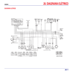
KYMCO UXV500 i
{
ON ROAD
GEAR
CHANGE SW
HAND
BRAKE SW
FR
STOP SW
G/Y
WINKER
RELAY
L
(FAN MOTOR)
(IGNITION)
(LIGHT)
(DC 12V POWER)
(FUEL)
(SPARE)
D
A
B
C
E
F
10A
15A
15A
10A
10A
IDLE
SPEED
CONTROL
THROTTLE
POSITION
TMAP
SENSOR
HAZARD
15A
SPEED
SENSOR
FUEL
RELAY
START
RELAY
12V 18AH
BATTERY
IC
FUEL INJ
4P
4P
1 2 3 4
G/Y
BR/L
R/Y
W/R(2)
O/R
R/L
B/R
R/Y
G/L
V/G(1)
GR/L
G/B(2)
BR/W(1)
G/O
V/R
V/B
V/G(1)
Y/B
G
SB
O
V/R
BR/W(2)
V/G(2)
O/B
STARTER MOTOR
G
Y/G
G
G/Y
BR/L
G
V
A B C D
Y/G
LG/R
Y/G
BR/B
B(1)
R/L
BR/L
B(1)
B(2)
R
Y/B
G
SB
O
R/W
ENG TEMP
(ETC)
R/W
R/W
Y/G
Y/R
W/BR
L/R
LG/R
W/B(2)
W/R
G
G
BR
START MAG
t
(ISC)
3P
4P
REAR
CLUTCH
STOP SW DIODE
G/Y
BR/L
SENSOR
(TPS)
(T-MAP)
W
G
R/W
W/B(1)
L
G
R/W
L/B
G
GR/W
R/W
Y/B
SB
W/BR
L/R
LG/R
W/B
W/R(1)
SB
HIBEAM
RELAY
LOBEAM
RELAY
G
GR/W
G
G10A
G15A
G15A
G15A
G10A
G10A
FUSE BOX ASS'Y
R
N
A
B
C
D
E
F
HAZARD
SW
P
D
G
GR
BR/L
G
V/R
B/W
G
RH FR WINKER
12V 10W
A:10A(FAN MOTOR)
B:15A(IGN)
C:15A(LIGHT)
D:15A(DC 12V POWER)
R/W
Y/B
SENSOR,
ANGLE
DETECT
BR/L
FUSE
FUSE
FUSE
FUSE
FUSE
FUSE
FUSE
FUSE
FUSE
FUSE
W
W/B(1)
L/B
G
BR
L
G
HEAD LIGHT
12V 35W/35W
FR POSITION
12V 5W
RH RR WINKER
12V 10W
G/B
TAIL/STOP LIGHT
12V 5/21W
METER
SB
R/W
BR/L
BR
L/R(2)
BAT+
IGN
BACKLIGHT
ENG CHECK
METER
METER FUEL
GND(-)
H.B
TURN(L,R)
HAND BRAKE
CAN(+)
CAN(-)
4WD &
SB
G
G/Y
BR
LG/R
L/R
W/BR
W/R
W/B(2)
Y/W
L/W
G/B
L(1)
O
SB
GR/W
B/L
W/L(2)
W/O
N
R
P
L
D
LOCK
G
G/Y
BR
LICENCE LIGHT
12V 5W
G
BR
G
BR
BR/L
RH RR WINKER
12V 10W
LG
HORN
TAIL/STOP LIGHT
12V 5/21W
O
G
G/Y
BR
W/B(1)
W
L
G
G
G/Y
BR
O
L/B
G
BR
G
BR
L/B(2)
B(2)
HEAD LIGHT
12V 35W/35W
FR POSITION
12V 5W
GR
COLOR
Y/R Y/BR
COLOR
BR/B
W
L
COLOR
IGN. COIL
SPARK PLUG
R/W Y/B
COLOR
E
B/W
G
BAT1 BAT2
R
B
L/B(2)
G
L(2)
B(2)
O
OFF
ON
PO
IG
R/Y
R/W
B/O
R/W
SB
PULSER
REG RECT ASSY
BLACK
GREEN
PO
O
L
W
Y
ORANGE
BLUE
WHITE
YELLOW
BR
R
RED
COMB SW
HA
4P
G/W
L/Y
COLOR
G/W(1)
L/Y
B
BAT
Y
Y
Y
LG
HAZARD SW
Y
Y
Y
FREE
PUSH
HI
Y
Y
Y
L
R
LO
R
FREE
PUSH
PO
C
B
ST
G
START SW
WR
R/W
G
R/Y
B/Y
L
4WD
W/L W/O
SENSOR POWER
R
BAT
1 2 3 4
IC
B
G
LIGHT SW
WINKER SW
HORN SW
HO
G
+12V SWITCH POWER
CAN-HIGH (+)
FAN
THERMO SW
2WD
COLOR
ENG CHECK
+12V MEMORY
CAN-LOW (-)
2WD 4WD 4WD
LOCK
SENSOR GROUND (1)
ISC (STEPB2)
CRANK ANGLE (+)
TILT SENSOR
ISC (STEPA1)
ISC (STEPA2)
CRANK ANGLE (-)
GEAR-D (L)
48P
2WD/4WD SW
4WD
LOCK
ISC (STEPB1)
BRAKE SWITCH
MANIFOLD PRESSVRE
AIR INTAKE TEMP
ENGINE COOLANT TEMP
LHCA-ENGINE STOP SW
SENSOR GROUND (2)
THROLLER POSITION
K-LINE
GEAR-B (H)
SPEED SIGNAL
GEAR-C (N)
FUEL RELAY
DIFF-LOCK INPUT
GEAR-A (R)
OVERRIDE
IGNITION RELAY
FAN RELAY
4WD INPUT
M
FAN
MOTOR
+12V SWITCHED POWER
POWER LIGHTING STARTER WINKER/ 2WD/4WD SW
DC12V SW
SW
HORN
SW
EFI ECU (M3 C)
FUEL PUMP
LEVEL SENSOR
1 2 3 4
4P
G
L(2)
2WD/4WD
ACTUATOR
(4WD&LOCK)
R
OFF
STARTER SOLENOID
INJECTOR
IGNITION COIL
GROUND (1)
GROUND (2)
4P
L
B
L
C
W/O
W/O
BR/L
W/L(1)
G
START
O/R
G
L/W
Y/W
G
ON
HI
SB
O
GR
G
CAN
DIAGNOSTICS
LO
B
BR/L
G/B
PO
OFF
R/W
Y/R
BR/B
L(1)
W
BR
W/L(2)
L2
L1
L
B
W/L(1)
G
R
B/L
EMI FILTER
SB
O
GR
LG
G/Y
RR
STOP SW
CAN-H(+)
CAN-L(-)
BAT(+)
BAT(-)
B(1)
BR/L
R/W
Y/R
BR/B
L(1)
W
BR
RH FR WINKER
12V 10W
B(1)
O
V/R
(A1)
(A2)
(A3)
BR/L (A4)
B/L
(B1)
(B2)
L/R(2) (B3)
R/W
(B4)
W/L(2) (C1)
(C2)
V/G(1) (C3)
BR/W(1)(C4)
L/Y
(D1)
B/W
(D2)
GR/L (D3)
G/O
(D4)
G/W(1) (E1)
(E2)
W/R
(E3)
G/B(2) (E4)
(F1)
O/B
(F2)
BR/W(2)(F3)
G/L
(F4)
(G1)
V/G(2) (G2)
V/B
(G3)
(G4)
G/L(2) (H1)
W/B(2) (H2)
(H3)
V
LG/R (H4)
B/R
(J1)
(J2)
L/R
(J3)
(J4)
B/O
(K1)
L(2) (K2)
W/L(1) (K3)
(K4)
(L1)
R/Y
(L2)
(L3)
W/R(2) (L4)
B/Y
(M1)
(M2)
G/B(1) (M3)
G/B(1) (M4)
G
L(2)
B(2)
G
O
BR
GR
SB
LG
ACG
SWITCHED FAN
POWER
RELAY
RELAY
BROWN
GRAY
SKY BLUE
LIGHT GREEN
0030Z-LKC3-E003(2010.02)