1
www.collegehillshonda.com
Accessory
INSTALLATION
INSTRUCTIONS
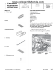
PARTS LIST
Remote Engine Starter Unit Kit
P/N 08E91-E22-100B
Application
Publications No.
AII 38215-38958
REMOTE ENGINE
STARTER SYSTEM
2006-2008 CIVIC 2-DOOR
(A/T ONLY)
Issue Date
FEB 2008
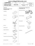
Remote Engine Starter Attachment Kit
P/N 08E92-SNA-100B
Engine starter harness
Transmitter
Control unit
Control unit bracket
Antenna
Relay bracket
Key ring
3 Black relays (4-pin)
Protective tape
Engine starter label
18 Wire ties
Fuse label
Accessory User’s Information Manual
Quick Start Guide
© 2008 American Honda Motor Co., Inc. - All Rights Reserved.
AII 38215-38958 (0802)
08E92-SVA-1B00-91
1 of 22
www.collegehillshonda.com
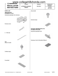
7 Foam cushion tapes
TOOLS AND SUPPLIES REQUIRED
Phillips screwdriver
Long blade flat-tip screwdriver
Small flat-tip screwdriver
6 mm Hex wrench
T25 Torx bit
Flange nut
3 mm and 7 mm Drill bit
File
Clip
Ratchet
10 mm Socket
Combination wrench
Isopropyl alcohol
Shop towel
Tape measure
Green relay (5-pin)
Clip remover
Diagonal cutters
Felt-tip pen
Center punch
Template
Scissors
2 Pairs of needle nose pliers
Rubber mallet
HDS (Honda Diagnostic System)
Masking tape
Safety goggles
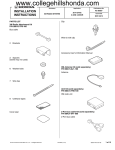
Illustration of the Engine Starter System Installed
on the Vehicle
ANTENNA
RELAY
(5-PIN)
ENGINE
STARTER
HARNESS
2 FUSES 40 A
INSTALLATION
Customer Information: The information in this
installation instruction is intended for use only by
skilled technicians who have the proper tools,
equipment, and training to correctly and safely add
equipment to your vehicle. These procedures
should not be attempted by “do-it-yourselfers.”
NOTE: The antenna should only be installed if the
ambient air temperature 15°C (60°F) or above.
1.
Make sure you have the anti-theft code for the
radio, then write down the radio station presets.
2.
Disconnect the negative cable from the battery.
CONTROL
UNIT
3 RELAYS
(4-PIN)
2 of 22
2 FUSES 3 A
7507010T
AII 38215-38958 (0802)
© 2008 American Honda Motor Co., Inc. - All Rights Reserved.
www.collegehillshonda.com
Setting the Control Unit
3.
SW : 1 RR Junction Unit
SW : 2 Trunk or Tailgate
SW : 3 Smart Entry
SW : 4 Horn or Buzzer Answer Back
SW : 5 Trunk Main SW
SW : 6 Reserve
Get the control unit. Using a small flat-tip
screwdriver, adjust the switches on the control
unit to the locations shown. Using a isopropyl
alcohol on a shop towel, clean the area where the
protective tape will attach. Attach the protective
tape to the control unit over the switches.
NOTE:
Removing the vehicle parts
•
The switches must be selected before the
control unit is plugged in.
4.
•
If the switch setting is not correct, the engine
starter will not operate correctly.
•
If setting the switches when the control unit is
installed in the vehicle, touch a metal part of
the screwdriver to a metal part of the vehicle to
discharge any static electricity.
•
If you change the switch settings with the unit
connected, you must disconnect the unit then
reconnect it before the settings will change.
Remove the trunk lid/fuel fill door opener cover
(six retaining tabs). Remove one self-tapping
screw.
SELFCOVER
6
TAPPING
RETAINING
SCREW
TABS
KEY
Unlock.
CONTROL
UNIT
SMALL
FLAT-TIP
SCREWDRIVER
TRUNK LID/
FUEL FILL
DOOR
OPENER
Discharge any
static electricity.
SWITCHES
5202191T
The switches must
be selected before
the control unit is
plugged in.
SWITCHES
SET
SW:1 RR Junction unit -----------------------> OFF
SW:2 Trunk or Tailgate ----------------------> OFF
SW:3 Smart Entry -----------------------------> OFF
SW:4 Horn or Buzzer Answerback ------> OFF
SW:5 Trunk Main SW -------------------------> OFF
SW:6 Reserve ----------------------------------> OFF
© 2008 American Honda Motor Co., Inc. - All Rights Reserved.
AII 38215-38958 (0802)
3 of 22
www.collegehillshonda.com
5.
Using the key, unlock the opener.
8.
6.
Remove the left front door sill trim (two retaining
tabs, five clips, and three hooks).
If equipped, remove the driver’s dashboard under
cover (turn the knob counterclockwise, and
release two clips and pin).
3 HOOKS
5 CLIPS
PIN
2 RETAINING
TABS
2 CLIPS
DRIVER’S
DASHBOARD
UNDER COVER
KNOB
FRONT
5202112T
LEFT FRONT
DOOR SILL TRIM
7.
5202200T
9.
Pull away the weatherstrip, and remove the left
kick panel (two clips).
WEATHERSTRIP
Remove the driver’s dashboard lower cover (eight
clips).
2 CLIPS
LEFT
KICK
PANEL
DRIVER’S
DASHBOARD
LOWER COVER
8 CLIPS
5202121T
5202220T
4 of 22
AII 38215-38958 (0802)
© 2008 American Honda Motor Co., Inc. - All Rights Reserved.
www.collegehillshonda.com
10. Lower the tilt lever, and pull the steering wheel
toward you. Insert a long blade flat-tip screwdriver
along the guide of the column lower cover, and
pry the retaining tab of the column upper cover.
12. Remove the column lower cover (two self-tapping
screws and one screw).
2 RETAINING TABS
Push.
COLUMN
LOWER
COVER
COLUMN
UPPER
COVER
2 HOOKS
COLUMN
LOWER
COVER
RETAINING
TAB
SCREW
2 SELF-TAPPING
SCREWS
5308530T
TILT LEVER
GUIDE
LONG BLADE
FLAT-TIP
SCREWDRIVER
6608050T
11. Push on the column lower cover in the area shown
to separate the column upper cover from the
column lower cover (two retaining tabs). Pull up to
remove the column upper cover (two hooks).
© 2008 American Honda Motor Co., Inc. - All Rights Reserved.
AII 38215-38958 (0802)
5 of 22
www.collegehillshonda.com
13. If equipped, use a small flat-tip screwdriver to
remove the left and right lens from the map light
console (four retaining tabs for each lens).
Remove the two bolts, and then release the map
light console.
15. Remove the cap from the left sunvisor (four
retaining tabs).
CONNECTOR
4 RETAINING
TABS
FRONT
MAP LIGHT
CONSOLE
LEFT
SUNVISOR
CAP
TORX
SCREW
4 RETAINING
TABS
LENS
16. Remove the left sunvisor (two T25 Torx screws,
and unplug the vehicle connectors).
BOLT
LENS
5217030T
6D01390T
14. Remove the sunvisor holders. Using a small flattip screwdriver, push the hook, and turn the
holder 90°, then pull it out.
17. Pull away the weatherstrip from the left front pillar
trim.
Strike perpendicularly
to the vehicle.
FRONT PILLAR
MAP LIGHT
CONSOLE
PIN
CLIP
STRIKE POINT
FRONT
PILLAR TRIM
SHOP
TOWEL
RUBBER
MALLET
LEFT FRONT
PILLAR TRIM
SUNVISOR
HOLDER
6 of 22
WEATHERSTRIP
SMALL
FLAT-TIP
SCREWDRIVER
CLIP
7503020T
6D01400T
18. Using a rubber mallet and a shop towel, gently tap
the left front pillar trim at the position shown to
release the clip. Gently tap the pillar trim at the
area marked as “SIDE CURTAIN AIRBAG”.
AII 38215-38958 (0802)
© 2008 American Honda Motor Co., Inc. - All Rights Reserved.
www.collegehillshonda.com
19. Pull away the weatherstrip from the left front pillar
trim. Remove the left front pillar trim (two clips).
LEFT FRONT
PILLAR TRIM
Installing the Antenna
21. Using scissors, cut out the template.
TEMPLATE
2 CLIPS
SCISSORS
Cut out.
WEATHERSTRIP
7503030T
5202100T
20. Remove the clip from the left front pillar trim, and
install a new clip on the left front pillar trim.
22. Secure the template to the windshield with the
tape by aligning it with the edge of the black
ceramic paint as shown.
NEW CLIP
EDGE OF
BLACK
CERAMIC
PAINT
BLACK
CERAMIC
PAINT
CLIP (Discard.)
LEFT FRONT
PILLAR TRIM
WINDSHIELD
5217110T
TEMPLATE
TAPE
Align the end
with the end
of the black
ceramic paint.
6D01210T
© 2008 American Honda Motor Co., Inc. - All Rights Reserved.
AII 38215-38958 (0802)
7 of 22
www.collegehillshonda.com
23. Using two pairs of needle-nose pliers, bend the
antenna plate according to the illustration and
measurement shown.
24. Measure the antenna cable as shown. Attach the
three foam cushion tapes to the antenna cable in
the measurement shown.
ANTENNA
CABLE
ANTENNA
FOAM
CUSHION TAPE
15 mm
(0.6 in.)
ANTENNA
360 mm
(14 in.)
8 mm
(0.3 in.)
30 mm
(1.2 in.)
30 mm
(1.2 in.)
6D01240T
25. Using isopropyl alcohol on a shop towel, clean the
area where the antenna will attach. Allow to dry
before proceeding.
SCALE
ROOF LINER
Clean with
isopropyl alcohol.
NEEDLE-NOSE PLIERS
TEMPLATE
ADHESIVE
BACKING
PLATE
6D01232T
PLATE
ANTENNA
6D01250T
26. Remove the adhesive backing from the antenna,
insert the antenna plate under the roof liner, and
attach the antenna to the windshield aligning the
template.
27. Remove the template.
8 of 22
AII 38215-38958 (0802)
© 2008 American Honda Motor Co., Inc. - All Rights Reserved.
www.collegehillshonda.com
28. Route the antenna cable under the roof liner
towards the driver’s side of vehicle, and down
along the vehicle harness. Be careful not to
crease the roof liner.
30. Using isopropyl alcohol on a shop towel, clean the
areas where the foam cushion tape will attach.
Under the roof liner, secure the antenna cable to
the roof panel with the two foam cushion tapes
(cut one foam cushion tape in half) in the areas
shown.
ROOF LINER
ROOF
LINER
FOAM CUSHION
TAPE (1/2)
VEHICLE
HARNESS
ANTENNA
CABLE
6D01260T
ANTENNA
CABLE
6D01270T
FOAM CUSHION
TAPE
29. Continue routing the antenna cable between the
front pillar and the dashboard.
31. Secure the antenna cable to the vehicle harness
with four wire ties as shown. Do not secure the
antenna cable to the drain tube.
FRONT PILLAR
4 WIRE TIES
DASHBOARD
VEHICLE
CLIP
DRAIN
TUBE
VEHICLE
HARNESS
ANTENNA
CABLE
ANTENNA
CABLE
5308192T
6D01410T
© 2008 American Honda Motor Co., Inc. - All Rights Reserved.
AII 38215-38958 (0802)
9 of 22
www.collegehillshonda.com
32. Secure the antenna cable to the vehicle harness
with a wire tie. Secure the wire tie between the
vehicle harness branching points.
WIRE TIE
VEHICLE
HARNESS
Installing the Control Unit Bracket
33. Locate the small square hole next to the small
round hole in the dashboard support bracket.
Under the dashboard, attach the control unit
bracket to the vehicle bracket near the front lower
pillar using a flange nut. If the vehicle is equipped
with a moonroof, be careful not to pull on the drain
tube.
VEHICLE
BRACKET
FRONT
ANTENNA
CABLE
BRANCHING
POINT
6D01281T
VEHICLE
BRACKET
FLANGE
NUT
6D01123T
CONTROL UNIT
BRACKET
10 of 22
AII 38215-38958 (0802)
© 2008 American Honda Motor Co., Inc. - All Rights Reserved.
www.collegehillshonda.com
Routing the Engine Starter Harness
34. Attach the 3A fuse labels to the engine starter
harness fuse case, and the 40A fuse labels to the
fuse block.
36. Route the engine starter harness 7-pin connectors
up the steering column and to the ignition switch.
Unplug the white vehicle 7-pin connector. Plug the
white engine starter harness 7-pin connectors into
the white vehicle 7-pin connectors.
LAYOUT OF RELAYS
WHEN VIEWED FROM FRONT
4-PIN
RELAY
(black)
IGNITION
SWITCH
VEHICLE 7-PIN
CONNECTOR
(white)
RELAY
BLOCK
5-PIN
RELAY
(green)
40A FUSE
LABEL
CLIP
FUSE
CASE
3A
FUSE
LABEL
ENGINE
STARTER
HARNESS
7-PIN
CONNECTOR
(white)
FUSE
BLOCK
4-PIN RELAY
(black)
6D01081T
6D01031T
35. Install the four relays to the engine starter harness
relay blocks. Be careful to install the relays
properly, or a malfunction will result.
© 2008 American Honda Motor Co., Inc. - All Rights Reserved.
AII 38215-38958 (0802)
11 of 22
www.collegehillshonda.com
37. Unplug the brown vehicle 7-pin connector, and
plug the brown engine starter harness 7-pin
connector into the brown vehicle 7-pin connector.
NOTICE Make sure that the engine starter harness
7-pin connector (brown) is connected to the vehicle
connector and it is locked securely. A loosely
connected connector can cause engine stall during
driving.
38. Disconnect the vehicle 8-pin connector on the rear
of the wiper switch and plug the engine starter
harness 8-pin connectors into the vehicle 8-pin
connector.
ENGINE STARTER
HARNESS
8-PIN CONNECTOR
VEHICLE 8-PIN
CONNECTOR
ENGINE STARTER
HARNESS 7-PIN
CONNECTOR (brown)
Pull the connector and
check that it is locked
securely.
WIPER
SWITCH
VEHICLE 7-PIN
CONNECTOR (brown)
(Not reconnected.)
6D01091T
6D01101T
39. Secure the connected 8-pin connector with a wire
tie to the engine starter harness.
CONNECTED 8-PIN
CONNECTOR
WIRE TIE
ENGINE
STARTER
HARNESS
WIPER
SWITCH
12 of 22
AII 38215-38958 (0802)
6D01071T
© 2008 American Honda Motor Co., Inc. - All Rights Reserved.
www.collegehillshonda.com
40. Wrap the vehicle 7-pin connector with one foam
cushion tape, then place the vehicle 7-pin
connector into the gap of the column.
VEHICLE 7-PIN
CONNECTOR
(brown)
(Squeeze into
this area.)
43. At the right of the steering shaft, locate the sub
joint box. Using a small flat-tip screwdriver, unplug
the vehicle 6-pin connector from the sub joint box.
Plug the engine starter harness 6-pin connectors
into the vehicle 6-pin connector and the subjoint
box.
ENGINE STARTER
HARNESS
GREEN
TAPE
VIEWED FROM
UNDERSIDE
4 WIRE
TIES
VEHICLE 6-PIN
CONNECTOR
SUB JOINT
BOX
FRONT
FOAM
CUSHION
TAPE
VEHICLE
LOCK HARNESS
WIRE
TIE
VEHICLE 7-PIN
CONNECTOR
VEHICLE
BRACKET
VEHICLE
HARNESS
ENGINE
STARTER
HARNESS
ENGINE STARTER
HARNESS 6-PIN
CONNECTOR
6D01111T
41. Secure the engine starter harness to the vehicle
harness with four wire ties in the areas shown.
The lock of the wire ties should face up.
VEHICLE 6-PIN
CONNECTOR
6D01162T
44. Attach the relay blocks and fuse case on the relay
bracket.
42. Remove the lower steering column support
bracket bolt. Attach the relay bracket to the
steering column support bracket and reinstall the
steering column support bracket bolt.
VEHICLE
HARNESS
WIRE
TIE
RELAY
BRACKET
FUSE
CASE
RELAY
BLOCK
STEERING COLUMN
SUPPORT BRACKET
BOLT (Reuse.)
STEERING
COLUMN
SUPPORT
BRACKET
RELAY
BRACKET
ENGINE STARTER
HARNESS
6D01302T
45. Secure the engine starter harness to the vehicle
harness using a wire tie.
6D01063T
© 2008 American Honda Motor Co., Inc. - All Rights Reserved.
AII 38215-38958 (0802)
13 of 22
www.collegehillshonda.com
46. With driver's dashboard under cover: Measure
the indicated dimension on the instrument panel
and mark with a felt-tip pen and a center punch.
47. Secure the engine starter harness to the vehicle
harness using a wire tie:
INSTRUMENT
PANEL
•
With driver's dashboard under cover: Secure
in the hole opened in the instrument panel.
•
Without driver's dashboard under cover:
Secure through the existing hole for under
cover securing.
WIRE TIE
View from below
12 mm
(0.5 in.)
FRONT
•
6 mm
(0.2 in.)
FELT-TIP PEN
CENTER
PUNCH
6D01351T
Drill a 3 mm hole and then a 7 mm hole at the
marked position of the instrument panel.
FUSE
BOX
– Wear safety goggles during drilling.
CLIP
WITH DRIVER’S DASHBOARD
UNDER COVER
6D01172T
– Using a file, remove the burrs at the edges
of the holes you made.
48. Use the clip on the engine starter harness to
secure the engine starter harness to the fuse box.
INSTRUMENT PANEL
DRILL BIT
(3, 7 mm)
DRILL
14 of 22
6D01361T
AII 38215-38958 (0802)
© 2008 American Honda Motor Co., Inc. - All Rights Reserved.
www.collegehillshonda.com
49. Disconnect the vehicle 42-pin, 4-pin, and 2-pin
connectors.
50. Plug the engine starter harness 4-pin and 2-pin
connectors into the fuse box.
VEHICLE 4-PIN VEHICLE 2-PIN
CONNECTOR
CONNECTOR
VEHICLE 42-PIN
CONNECTOR
NOTICE Check that the engine starter harness 4-pin
and 2-pin connectors are connected to the fuse box
and they are locked securely. Loosely connected
connectors can cause engine stall during driving.
FUSE BOX
4-PIN
CONNECTOR
PORT
FUSE BOX
2-PIN
CONNECTOR
PORT
FOAM
CUSHION
TAPE
VEHICLE
HARNESS
FRONT VIEW
VEHICLE 2-PIN
CONNECTOR
VEHICLE 4-PIN
CONNECTOR
LOCK
VEHICLE 42-PIN
CONNECTOR
WIRE TIE
VEHICLE
2-PIN
CONNECTOR
6D01430T
VEHICLE
4-PIN
CONNECTOR
ENGINE
STARTER
HARNESS
4-PIN
CONNECTOR
ENGINE
FUSE BOX
STARTER
HARNESS
2-PIN
CONNECTOR
Pull the connector and
check that it is locked
securely.
6D01292T
51. Wrap foam cushion tape to the vehicle 2-pin and
4-pin connectors and secure them with a wire tie.
Then, secure the vehicle harness with a wire tie.
Reconnect the vehicle 42-pin connector.
© 2008 American Honda Motor Co., Inc. - All Rights Reserved.
AII 38215-38958 (0802)
15 of 22
www.collegehillshonda.com
52. Behind the fuse box, unplug the blue vehicle 23pin connector from the inside of the front lower
pillar, and plug the blue engine starter harness 23pin connectors into the blue vehicle 23-pin
connector. If the vehicle 23-pin connector is
difficult to disconnect, perform the work after first
disconnecting the connector on the upper side.
54. Install the clip from the engine starter harness to
the fuse box bracket behind the fuse box.
GROUND BOLT
(Reuse.)
FRONT
FUSE BOX
VEHICLE 23-PIN
CONNECTOR
(blue)
ENGINE STARTER
HARNESS GROUND
TERMINAL
ENGINE
STARTER
CLIP
HARNESS
FRONT
SIDE VIEW
ENGINE STARTER
HARNESS 23-PIN
CONNECTOR (blue)
FUSE BOX
BRACKET
FRONT
LOWER
PILLAR
6D01181T
6D01132T
53. Unplug the white vehicle 14-pin connector at the
front lower pillar behind the fuse box, and plug the
engine starter harness 14-pin connectors into the
white 14-pin connector. Attach the engine starter
harness 14-pin connector to the vehicle 14-pin
connector.
FUSE BOX
55. Remove the ground bolt from the vehicle. Secure
the engine starter harness ground terminal with the
ground bolt you just removed.
WHITE VEHICLE
14-PIN
CONNECTOR
ENGINE
STARTER
HARNESS
14-PIN
CONNECTOR
VEHICLE 14-PIN
CONNECTOR (white)
16 of 22
6D01152T
AII 38215-38958 (0802)
© 2008 American Honda Motor Co., Inc. - All Rights Reserved.
www.collegehillshonda.com
Installing the Control Unit
59. Using isopropyl alcohol on a shop towel, clean the
area where the engine starter label will attach.
56. Connect the antenna cable terminal and the
engine starter harness 18-pin connector to the
control unit.
HOOD
ANTENNA CABLE
TERMINAL
(Connect first.)
ADHESIVE
BACKING
ENGINE
STARTER LABEL
FRONT
CONTROL
UNIT
CONTROL UNIT
BRACKET
ENGINE STARTER
HARNESS 18-PIN
CONNECTOR
6D01312T
57. Install the control unit on the control unit bracket.
58. Bundle the excess antenna cable with two wire
ties and secure it with one wire tie to the vehicle
harness.
ANTENNA
CABLE
6D01421T
60. Attach the engine starter label to the back of the
hood.
61. Check that all wire harnesses are routed properly
and all connectors are plugged in.
62. Reinstall all removed parts. Check that all clips
and other fasteners are installed securely. Take
care not to pinch the airbag with a clip during
reinstallation of the front pillar trim. Do not push
the front pillar trim excessively.
63. Reconnect the negative cable to the battery.
Check that the electrical accessory and other
electrical systems function properly.
64. Perform REMOTE ENGINE STARTER
REGISTRATION, on pages 18-20, and FUNCTION
CHECK, on page 21.
65. Enter the customer’s radio anti-theft code, and
reset the radio station presets.
66. Reset the clock.
WIRE
TIE
VEHICLE
HARNESS
7401020T
© 2008 American Honda Motor Co., Inc. - All Rights Reserved.
AII 38215-38958 (0802)
17 of 22
www.collegehillshonda.com
REMOTE ENGINE STARTER REGISTRATION
5.
1.
Acquire the PCM code from ISIS.
2.
Connect the HDS tester to the OBD II data link
connector, then turn the ignition switch to the ON
(II) position.
3.
Start the HDS, and click the car icon.
Select Honda Systems, then click the check
button.
CAR ICON
Select
“Honda Systems.”
CHECK BUTTON
752503AS
6.
Select R/C ENG STARTER and click the check
button.
752501AS
4.
Input the VIN and other required information into
the HDS, then click the check button.
Select
“R/C ENG STARTER.”
CHECK BUTTON
752504AS
Input the VIN and
other required
information.
18 of 22
CHECK BUTTON
752502AS
AII 38215-38958 (0802)
© 2008 American Honda Motor Co., Inc. - All Rights Reserved.
www.collegehillshonda.com
7.
A REMARKS message will display. Click the
check button.
9.
“REMARKS” message
The following message will display: Obtain PCMcode (IMMOBILIZER PCM CODE) from iN. This
vehicle’s VIN will be required to obtain the
password. (USA). Click the check button.
“Obtain PCM-code"
message
CHECK BUTTON
752505AS
CHECK BUTTON
8.
Select REGISTER REMOTE CONTROL ENGINE
STARTER UNIT, then click the check button.
752507AS
10. Input the PCM code, then click the check button.
NOTE: To ensure security, the PCM code
(password) is changed every day, so it is
impossible to register the remote control engine
starter if the dates of the PCM code acquisition
and registration are different. The date of the HDS
tester should also be the same.
Input the PCM code.
Select
“REGISTER REMOTE CONTROL
ENGINE STARTER UNIT.”
CHECK BUTTON
752506AS
CHECK BUTTON
752509AS
© 2008 American Honda Motor Co., Inc. - All Rights Reserved.
AII 38215-38958 (0802)
19 of 22
www.collegehillshonda.com
11. The following message will display: The
registration of the Remote Control Engine
Starter Unit has been completed. Click the
check button.
"Registration" message
CHECK BUTTON
752510AS
12. The following message will display: Check that
the engine can be started by the Transmitter.
Click the check button.
"Check that the engine can be started
by the Transmitter"
CHECK BUTTON
752511AS
13. Perform the function check on page 21, then
disconnect the HDS.
20 of 22
AII 38215-38958 (0802)
© 2008 American Honda Motor Co., Inc. - All Rights Reserved.
www.collegehillshonda.com
FUNCTION CHECK
Operating Conditions
•
The hood is closed.
•
The shift lever is in Park.
•
The key is not in the ignition switch.
•
All doors and trunk are closed and locked.
Inspection
1.
Within 1 second, press the command button and then the start button on the transmitter.
The engine should start if all operating conditions are met.
Does the engine start?
Yes - Operation is normal.
No:
• Make sure all operating conditions are met.
• Check the engine starter harness connections.
• Connect the HDS and check for an indicated failure.
(Refer to the appropriate service manual for details.)
2.
Press the command button on the transmitter, and within 1 second,
press the stop button. The engine should stop.
Does the engine stop?
Yes - Operation is normal.
No - Check the engine starter harness connections.
3.
DISPLAY
STOP
BUTTON
COMMAND
BUTTON
After the engine has stopped, start the engine again, and check that the
engine stops after each of the following conditions:
START
BUTTON
NOTE: After each test the ignition key must be cycled, or the driver’s
door must be opened and closed.
– Move the shift lever out of the P position.
TRANSMITTER
– Unlock or open the doors or the trunk lid.
732904AY
– Open the hood.
– Insert the key in the ignition switch.
– Press on the brake pedal.
Does the engine stop after each of these tests?
Yes - Operation is normal.
4.
No - Check the engine starter harness connections.
Check that the power windows or the moonroof does not function when the engine is started with the transmitter.
5.
Press the command button on the transmitter twice and check the vehicle condition on the display.
6.
Check the operation of the transmitter when the vehicle is 100 m to 150 m (325 to 490 ft.) away and when the
vehicle is in direct sight.
© 2008 American Honda Motor Co., Inc. - All Rights Reserved.
AII 38215-38958 (0802)
21 of 22
www.collegehillshonda.com
How to Program an Additonal Transmitter
1.
Connect the HDS to the data link connector.
2.
Start the HDS and click on the car icon.
3.
Input the vehicle's VIN and other required
information.
4.
Select Honda Systems.
5.
Select R/C Engine Starter.
6.
Select REGISTER NEW TRANSMITTER.
7.
When "Ready to program the new transmitter"
shows, select ENTER.
8.
Press and release the Command button.
9.
Press and release the Stop button.
10. Perform the function check on both transmitters.
NOTE: Only 2 remotes can be stored in the
system's memory.
22 of 22
AII 38215-38958 (0802)
© 2008 American Honda Motor Co., Inc. - All Rights Reserved.