1
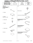
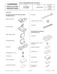
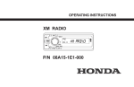
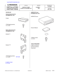
www.collegehillshonda.com/parts
Accessory
INSTALLATION
INSTRUCTIONS
Application
Publications No.
AII 25886
XM RADIO SYSTEM
The XM Radio system will not fit in a vehicle
equipped with a navigation system or a rear
entertainment system.
PARTS LIST
XM Radio Attachment Kit (sold separately):
P/N 08B15-S9V-100
2003-2004 PILOT
Issue Date
AUG 2003
15 Wire ties
5 Wire ties with clips
DIN cable
2 Cushion tapes
XM radio harness
7 EPT sealers
Fuse label
Unit bracket
2 Subantenna cables
Double-sided adhesive tape,
53 x 28 mm
Harness hook (Not used)
6 Washer-screws, 4 x 8 mm
Display module pocket
4 Washer-bolts, 6 x 12 mm
Clip nut
4 Flange nuts, 4 mm
3 Self-tapping screws
2 Washer-screws, 4 x 12 mm
(Not used)
Antenna plate
Double-sided adhesive tape,
60 x 60 mm
© 2003 American Honda Motor Co., Inc - All Rights Reserved.
AII 25886 (0308)
08B15-S9V-1001-91
1 of 14
XM Antenna Kit (sold separately):
P/N 08A15-1E1-100
Antenna
Base Kit (sold separately):
P/N 08A15-1E1-000
Display module
TOOL AND SUPPLIES REQUIRED
#2 Phillips screwdriver
Flat-tip screwdriver
Utility knife
Diagonal cutters
Push pin
Tape measure
Shop towel
Scissors
Ratchet
8 mm, 10 mm, and 14 mm Sockets
8 mm, 10 mm, and 14 mm Combination wrenches
Felt-tip pen
Isopropyl alcohol
Drill
3 mm and 10 mm drill bits
Eye protection (face shield, safety goggles, etc.)
FM modulator unit
Receiver unit
Owner’s Manual
DIN Bezel (sold separately):
P/N 08B23-S9V-100A
DIN bezel
2 of 14
AII 25886 (0308)
© 2003 American Honda Motor Co., Inc - All Rights Reserved.
Illustration of an Installed XM Radio System
INSTALLATION
Customer Information: The information in this
installation instruction is intended for use only by
skilled technicians who have the proper tools,
equipment, and training to correctly and safely add
equipment to your vehicle. These procedures should
not be attempted by “do-it-yourselfers.”
ANTENNA
FM
MODULATOR
UNIT
1.
Make sure you have the anti-theft code for the
radio, then write down the frequencies for the
preset buttons.
2.
Disconnect the negative cable from the battery.
3.
Using a flat-tip screwdriver wrapped with a shop
towel, gently pry out on the audio panel to remove
the five clips. Unplug the connectors, and remove
the audio panel.
DISPLAY
MODULE
VEHICLE
CONNECTOR
3121110M
AUDIO UNIT
RECEIVER UNIT
ANTENNA
VEHICLE
20-PIN
CONNECTOR
VEHICLE
ANTENNA
CABLE
DISPLAY
MODULE
XM RADIO
HARNESS
SUBANTENNA
CABLE
AUDIO PANEL
RECEIVER UNIT
CLIPS (5)
FM MODULATOR
UNIT
DIN CABLE
2N27010M
© 2003 American Honda Motor Co., Inc - All Rights Reserved.
AII 25886 (0308)
3 of 14
4.
Remove the four screws that fasten the audio
bracket. Pull the audio unit out toward you, and
unplug the vehicle connector and antenna cable
from the rear of the audio unit. If equipped with a
cassette/in-dash CD changer, unplug the
additional connectors.
VEHICLE CONNECTOR
(If equipped, unplug the
additional connectors.)
AUDIO UNIT
6. Remove the center panel (four self-tapping screws
and two clips, and unplug the vehicle accessory
power outlet).
CLIPS (2)
CENTER
PANEL
ANTENNA
CABLE
AUDIO
BRACKET
SELFTAPPING
SCREWS
7.
AUDIO
BRACKET
SCREW
(Reuse.)
5.
Remove the driver’s and passenger’s center
console trim pieces (three clips each). Take care
not to damage the clips.
PASSENGER’S
CENTER
CONSOLE TRIM
DRIVER’S CENTER
CONSOLE TRIM
VEHICLE
CONNECTOR
If equipped with a cigarette lighter, remove the four
self-tapping screws. Pull the center panel by
releasing the two clips. Unplug the two lighter
harness terminals, and remove the illumination
light. Remove the center panel.
With Cigarette Lighter:
LIGHT HOLDER
ILLUMINATION
LIGHT
LIGHTER
HARNESS
TERMINALS
SELFTAPPING
SCREWS (4)
CENTER
PANEL
CLIPS (2)
CIGARETTE
LIGHTER
CLIPS (3)
4 of 14
AII 25886 (0308)
© 2003 American Honda Motor Co., Inc - All Rights Reserved.
8.
Remove the four screws that fasten the left and
right vehicle bracket. Pull the heater control unit
and pocket toward you, and unplug the vehicle
connectors.
10. Slide the clip nut onto the display module pocket
flange.
DISPLAY
MODULE
POCKET FLANGE
VEHICLE
CONNECTOR
HEATER
CONTROL UNIT
CLIP NUT
LEFT
VEHICLE
BRACKET
Clean with
isopropyl alcohol.
DISPLAY
MODULE
POCKET
SCREW
9.
RIGHT
VEHICLE
BRACKET
DISPLAY
MODULE
3131010M
Remove the left and right vehicle brackets (six
self-tapping screws), and separate the heater
control unit from pocket. Set the pocket aside, it
will not be reused.
3121040M
ADHESIVE
BACKINGS
SELF-TAPPING SCREW
(Reuse.)
LEFT VEHICLE
BRACKET
HEATER
CONTROL UNIT
Clean with
isopropyl alcohol.
DOUBLE-SIDED
ADHESIVE TAPE
SELFTAPPING
SCREW
(Reuse.)
11. Attach the display module to the display module
pocket:
SELFTAPPING
SCREW
SELFTAPPING
SCREW
POCKET
RIGHT VEHICLE
BRACKET
© 2003 American Honda Motor Co., Inc - All Rights Reserved.
AII 25886 (0308)
•
Using isopropyl alcohol on a shop towel, clean
the center of the back of the display module
where the double-sided adhesive tape will
attach.
•
Remove on backing from the double-sided
adhesive tape, and attach it to the display
module.
•
Remove the remaining backing from the
double-sided adhesive tape. Route the display
module cable through the hole of the display
module pocket, and attach the display module
to the pocket.
5 of 14
14. Fit the DIN bezel around the display module
pocket. Set the heater control unit on the display
module pocket, and reinstall the left and right
vehicle brackets using the two self-tapping screws
removed in step 9. Attach the display module to
brackets with three self-tapping screws supplied
with the XM radio attachment kit.
SELFTAPPING
SCREW
(Reuse.)
LEFT
VEHICLE
BRACKET
16. Remove the driver's seat rear cover (four clips).
Take care not to damage the clips.
DRIVER’S SEAT
HEATER
CONTROL
UNIT
RIGHT
VEHICLE
BRACKET SELFTAPPING
SCREW
(Reuse.)
SELF-TAPPING
SCREWS
(Supplied with
XM radio
attachment
kit)
DISPLAY
MODULE
POCKET
DIN
BEZEL SELF-TAPPING
SCREWS
(Supplied with
XM radio
attachment kit)
DRIVER’S SEAT
REAR COVER
CLIPS (4)
3121051M
17. Remove the drivers seat (four bolts). Move the
driver seat out of the way.
Routing the XM Radio Harness
15. Remove the driver’s seat front cover (four clips).
DRIVER’S SEAT
DRIVER’S
SEAT
DRIVER’S
SEAT FRONT
COVER
CLIPS (4)
BOLTS (4)
6 of 14
AII 25886 (0308)
© 2003 American Honda Motor Co., Inc - All Rights Reserved.
18. On the driver’s side of the vehicle, remove the
center console lower cover (gently pull the cover
out toward you to release the seven clips). Take
care not to damage the clips.
20. Route the XM radio harness and two subantenna
cables from the dashboard opening to driver’s
floor. Using one cushion tape, attach it to the
vehicle frame.
DRIVER’S
SEAT
DASHBOARD
OPENING
Align.
CUSHION TAPE
50 mm
DRIVER’S CENTER
CONSOLE LOWER
COVER
CLIPS (7)
19. Get the XM radio harness, the subantenna cables,
and the fuse labels. Attach the 2A and 5A fuse
labels to the fuse cases on the XM radio harness.
FUSE LABEL
FUSE CASE
Use
these
labels.
© 2003 American Honda Motor Co., Inc - All Rights Reserved.
FUSE
LABEL
(2A)
XM RADIO
HARNESS
SUBANTENNA
CABLE
Clean with
isopropyl
alcohol.
21. Pull the XM radio harness and subantenna cables
out through the dashboard opening approximately
50 mm.
FUSE3121031M
LABEL
(5A)
AII 25886 (0308)
7 of 14
22. Plug the audio unit vehicle 20-pin connector into
the XM radio 20-pin connector that is blue-taped to
the XM radio harness. Wrap one EPT sealer
around the subantenna cable in the area shown.
SUBANTENNA
CABLE
25. Place the display module/heater control unit
assembly near the dashboard opening, and route
the display module cable along the XM radio
harness and the subantenna cables.
VEHICLE FRAME
(Clean with
isopropy
alcohol.)
EPT
SEALER
EPT SEALER
SUBANTENNA
CABLE
DISPLAY MODULE
CABLE
VEHICLE
ANTENNA
CABLE
XM RADIO
HARNESS 20-PIN
CONNECTOR
DISPLAY MODULE/HEATER
CONTROL UNIT ASSEMBLY
VEHICLE 20-PIN
CONNECTOR
SUBANTENNA CABLES
23. Plug the vehicle antenna cable into the
subantenna cable.
XM RADIO HARNESS
DISPLAY MODULE
CABLE
26. Using isopropyl alcohol on a shop towel, clean the
vehicle frame, then attach one EPT sealer on the
edge of the vehicle frame to protect the cables.
VEHICLE ANTENNA
CABLE
WIRE TIE
SUBANTENNA
CABLE
VEHICLE
HARNESS
XM RADIO
HARNESS
27. Remove the two screws from the side brackets at
the heater control unit opening. Plug in the heater
control unit connectors, and slide the display
module/heater control unit assembly into the
dashboard opening. Reinstall the two side bracket
screws, and the four heater control unit screws
removed in step 8.
FRAME
PIPE
DISPLAY MODULE/HEATER
CONTROL UNIT ASSEMBLY
SCREWS
(Removed
in step 8.)
3131021M
24. Secure the XM radio harness and subantenna
cables to the vehicle harness with a wire tie.
8 of 14
SCREW
(reused)
SCREW
(reused)
AII 25886 (0308)
© 2003 American Honda Motor Co., Inc - All Rights Reserved.
28. Plug the XM radio harness 20-pin connector and
sub antenna cable into the audio unit, and
carefully slide the audio unit into the dashboard.
Reinstall the four audio unit screws.
XM RADIO
HARNESS 20-PIN
CONNECTOR
30. Continue routing cables through the center
console and toward the rear of the vehicle. Using
scissors, cut one cushion tape in half. Clean the
vehicle frame with isopropyl alcohol, and attach
half of the cushion tape to the vehicle frame in the
area shown.
VEHICLE FRAME
(Clean with
isopropyl alcohol.)
CUSHION
TAPE
VEHICLE
HARNESS
XM RADIO
HARNESS
AUDIO
UNIT
SUBANTENNA
CABLE
SCREW (4)
(reused)
SUBANTENNA
CABLE
29. Secure the XM radio harness, subantenna cables,
and display module cable to the vehicle pipe with
two wire ties.
VEHICLE
PIPE
2N27130M
CUSHION
TAPE
Cut.
DISPLAY MODULE
CABLE
31. Secure the XM radio harness and subantenna
cables with one wire tie, but don’t tighten the wire
tie at this time.
DISPLAY MODULE
CABLE
CUSHION
VEHICLE TAPE
HARNESS
VEHICLE FRAME
(Clean with
isopropyl alcohol.)
WIRE
TIES
SUBANTENNA
CABLE
WIRE TIE
DISPLAY MODULE
CABLE
DISPLAY
MODULE
CABLE
SUBANTENNA
CABLE
XM RADIO
HARNESS
© 2003 American Honda Motor Co., Inc - All Rights Reserved.
XM RADIO
HARNESS
32. Attach the remaining half of the cushion tape to
the vehicle frame in the area shown.
AII 25886 (0308)
9 of 14
33. Measure and slit the driver’s floor carpet in the
area shown. Be careful not to damage the
subantenna cables and XM radio harness when
cutting the floor carpet.
Installing the Antenna
35. On the driver's side of the vehicle, remove the
weatherstrip from the left front door opening in the
area shown, then remove the left front "A" pillar
trim (two clips).
FLOOR
CARPET
CLIPS (2)
slit
50 mm
WEATHERSTRIP
WIRE TIE
LEFT FRONT
"A" PILLAR TRIM
DISPLAY MODULE
CABLE
SUBANTENNA
CABLE
XM RADIO
HARNESS
36. Remove the dashboard side cover (four clips, one
retaining tab, and seven hooks).
34. Route the XM radio harness and subantenna
cables under the floor carpet and out the slit.
Secure the cables with one wire tie.
HOOKS (7)
CLIPS (4)
RETAINING
TAB
10 of 14
AII 25886 (0308)
DASHBOARD
SIDE COVER
© 2003 American Honda Motor Co., Inc - All Rights Reserved.
37. Remove the fuel lid door opener lever, then
remove the left front door sill trim (three clips and
two retaining tabs).
39. Get two EPT sealers. Using scissors, cut two
EPT sealers into six pieces. Wrap the them
around the antenna unit cable at the
measurements shown.
ANTENNA
UNIT
RETAINING
TAB
60 mm
FUEL LID DOOR
OPENER LEVER
60 mm
60 mm
60 mm
200 mm
60 mm
LEFT
FRONT
DOOR SILL
TRIM
ADHESIVE
BACKING
(Remove.)
60 x 60 mm
DOUBLE-SIDED
ADHESIVE TAPE
EPT SEALER
CLIP
CLIPS (2)
Cut.
40. Using isopropyl alcohol on a shop towel, clean the
bottom of the antenna unit. Remove the backing
from the 60 x 60 mm double-sided adhesive tape,
and attach it to the bottom of the antenna unit.
38. Remove the weatherstrip from the left kick panel.
Remove the upper clip from the left kick panel,
then pull the left kick panel out toward you to
release the retaining clip.
ANTENNA
UNIT
ADHESIVE
BACKING
(Remove.)
ANTENNA UNIT
CABLE
WEATHERSTRIP
ANTENNA
PLATE
ADHESIVE
BACKING
(Remove.)
DASHBOARD
Clean with
isopropyl alcohol.
CLIP
LEFT KICK
PANEL
CLIP
© 2003 American Honda Motor Co., Inc - All Rights Reserved.
41. Using isopropyl alcohol on a shop towel, clean the
areas where the antenna unit and the antenna
plate will attach.
42. Remove the adhesive backing from the antenna
unit and the antenna plate, and attach them to the
dashboard in the area shown.
AII 25886 (0308)
11 of 14
43. Route the antenna unit cable along the front
windshield and the top of the dashboard. Insert the
antenna unit cable with the EPT seals between
the windshield and the dashboard.
ANTENNA
UNIT CABLE
Insert.
45. Secure the antenna unit cable to the vehicle
harness with two wire ties.
ANTENNA
UNIT CABLE
VIN IDENTIFICATION
PLATE
(Don’t hide the VIN
number with the
antenna unit cable.)
VEHICLE
HARNESS
FRONT
WINDOW
GLASS
ANTENNA
UNIT
CABLE
Insert.
WIRE
TIES
Route under the
dashboard.
DASHBOARD
44. Route the antenna unit cable down and under the
dashboard.
2N27050M
46. Below the dashboard, secure the antenna unit
cable to the vehicle harness with two additional
wire ties.
VEHICLE
HARNESS
ANTENNA
UNIT CABLE
WIRE
TIE
WIRE
TIE
ANTENNA UNIT
CABLE
ANTENNA
UNIT CABLE
2N27060M
2N27040M
12 of 14
AII 25886 (0308)
© 2003 American Honda Motor Co., Inc - All Rights Reserved.
47. Continue routing the antenna unit cable alongside
the vehicle harness, and out through the hole in
the floor carpet under the driver's seat. Secure the
antenna unit cable to the vehicle harness with four
wire ties in the area shown.
FLOOR
CARPET
50. Get the DIN cable. Plug the DIN cable into the FM
modulator unit and the receiver unit.
FM
MODULATOR
UNIT
RECEIVER UNIT
ANTENNA
UNIT CABLE
HOLE
UNIT
BRACKET
51. Position the unit assembly under the driver’s seat.
Plug the XM radio harness 4-pin connector and
the antenna unit cables into the receiver unit. Plug
the XM radio harness 3-pin connector, the display
module cable, and the subantenna cables into the
FM modulator unit.
WIRE TIES
VEHICLE
HARNESS
VEHICLE
HARNESS
2N27070M
Installing the Receiver Unit and FM Modulator Unit
FM
MODULATOR
UNIT
48. Install the receiver unit to the unit bracket with the
four 4 x 8 mm washer-screws, and four 4 mm
flange nuts.
FM
MODULATOR
UNIT
RECEIVER
UNIT
DIN CABLE
RECEIVER UNIT
FRONT
FM
MODULATOR
UNIT
CABLES
4 x 8 mm
WASHERSCREWS (4)
ANTENNA
UNIT CABLE
SUB
ANTENNA
CABLE
DISPLAY
MODULE
CABLE
4-PIN
CONNECTOR
3-PIN
CONNECTOR
XM RADIO
HARNESS
4 mm
FLANGE
NUTS (4)
4 x 8 mm
WASHERSCREWS (2)
UNIT
BRACKET
SUBANTENNA
CABLE
2N27080M
EPT SEALER
52. Wrap one EPT sealer around the subantenna
cables.
49. Install the FM modulator unit tn the unit bracket
with the two 4 x 8 mm washer-screws.
© 2003 American Honda Motor Co., Inc - All Rights Reserved.
AII 25886 (0308)
13 of 14
53. Get the five wire ties with clips and two wire ties.
Secure all of the cablse to the unit bracket in the
order shown:
XM radio harness, subantenna cables, and the
display module cable.
55. Slide the driver's seat forward, and install the unit
bracket to the driver’s seat rails using four
6 x 12 mm washer-bolts. Tighten the bolts
securely.
DRIVER’S SEAT
UNIT BRACKET
XM radio harness, subantenna cables, and the
display module cable.
6 x 12 mm
WASHERBOLTS (4)
Antenna unit cable, XM radio harness,
subantenna cable, and the display module
cable.
Subantenna cable and FM display unit cable.
FM modulator unit cable and the antenna unit
cable.
DISPLAY
MODULE
CABLE
ANTENNA
UNIT CABLE
WIRE
TIE
SUBANTENNA
CABLE
FM
MODULATOR
UNIT
WIRE
TIE
SEAT RAIL
XM RADIO
HARNESS
2N27100M
56. Check that all of the wire harnesses are routed
properly and all of the connectors are plugged in.
57. Reconnect the negative cable to the battery.
58. Set one of the radio station presets to FM 88.7
and check the operation of the XM radio. If
necessary, use the XM radio Owner’s Manual
supplied.
WIRE TIES
WITH CLIPS
WIRE
TIE
WITH
WIRE CLIP
TIE
WITH
CLIP
59. Reinstall the driver’s seat. Take care not to pinch
the display module cable. Torque the seat bolts to
47 N·m (35 lbf·ft).
60. Reinstall all of the removed parts.
61. Enter the customer’s radio anti-theft code, and
reset the radio station presets.
ANTENNA UNIT
CABLE
(Bundle the
excess cable.)
62. Set the clock.
FM
MODULATOR
ANTENNA
CABLE
NOTE: Whenever the battery is disconnected,
the driver’s window AUTO up function is disabled.
2N27090M
63. Start the engine. Push down on the driver’s
window switch until the window is fully open.
64. Pull up on the driver’s window switch and close
the window completely, then hold the switch up
for at least 2 seconds or more.
65. Test the window AUTO up function.
14 of 14
AII 25886 (0308)
© 2003 American Honda Motor Co., Inc - All Rights Reserved.