1
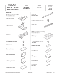
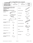
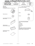
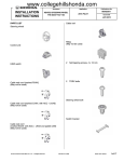
www.collegehillshonda.com/parts Accessory INSTALLATION INSTRUCTIONS Application Publications No. All 23607 CD CHANGER ATTACHMENT 2003-2004 PILOT Issue Date MAY 2002 PARTS LIST CD Changer Attachment Kit (sold separately): P/N 08B26-S9V-100 8 Wire ties Right base bracket 4 Washer-screws, 4 x 8 mm 2 Wire clips Left base bracket CD Changer (sold separately): P/N 08A26-1B1-100 Right changer bracket CD changer Left changer bracket 4 Washer-screws, 4 x 6 mm (Not used) BUS Cable Adhesive seal sheet Locking covers 4 Flange bolts, 6 x 12 mm 4 Flange nuts CD magazine 2 EPT seals (Black) Owner’s Manual 2 Cushion tapes (Gray) © 2002 American Honda Motor Co., Inc - All Rights Reserved. Small wire tie (Not used) All 23607 (0205) 08B26-S9V-1000-91 1 of 8 • TOOLS AND SUPPLIES REQUIRED Flat-tip screwdriver Phillips screwdriver Shop towel Diagonal cutters 10 mm Combination wrenches Isopropyl alcohol Utility knife Remove the four screws that fasten the audio brackets. Pull the audio unit out toward you, unplug the vehicle connector and antenna lead from the rear of the audio unit. VEHICLE CONNECTOR AUDIO UNIT ANTENNA LEAD INSTALLATION AUDIO BRACKET Customer Information: The information in this installation instruction is intended for use only by skilled technicians who have the proper tools, equipment, and training to correctly and safely add equipment to your vehicle. These procedures should not be attempted by “do-it-yourselfers.” 1. Make sure you have the anti-theft code for the radio, then write down the frequencies for the preset buttons. 2. Disconnect the negative cable from the battery. 3. Remove the audio unit. SCREWS (Reuse.) Without Navigation Unit: • Using a flat-tip screwdriver wrapped with a shop towel, gently pry out on the audio panel to remove the five clips. Unplug the connectors and remove the audio panel. AUDIO BRACKET With Navigation Unit: • Remove the driver’s and passenger’s center console trim pieces (three clips each). Take care not to damage the clips. VEHICLE CONNECTOR PASSENGER’S CENTER CONSOLE TRIM DRIVER’S CENTER CONSOLE TRIM AUDIO PANEL CLIPS (3) CLIPS (5) 2 of 8 All 23607 (0205) © 2002 American Honda Motor Co., Inc - All Rights Reserved. • Remove the center panel (four self-tapping screws, two clips, and unplug the vehicle accessory power outlet). 4. CLIPS (2) On the driver’s side of the vehicle, gently pull the center console lower cover out toward you to release the seven clips and remove the center console lower cover. Take care not to damage the clips. DRIVER’S SEAT CENTER PANEL SELFTAPPING SCREW DRIVER’S CENTER CONSOLE LOWER COVER VEHICLE CONNECTOR 5. • Remove the four screws that fasten the audio brackets. Pull the audio unit/heater control unit out toward you, unplug the vehicle connectors and antenna lead. CLIPS (7) Remove the driver’s seat front cover by pulling it toward you. Take care not to damage the clips. DRIVER’S SEAT ANTENNA LEAD HEATER CONTROL UNIT AUDIO BRACKET VEHICLE CONNECTOR DRIVER’S SEAT FRONT COVER AUDIO BRACKET SCREW CLIPS (4) AUDIO UNIT © 2002 American Honda Motor Co., Inc - All Rights Reserved. All 23607 (0205) 3 of 8 Routing the BUS cable With Navigation Unit: 6. • Route the BUS cable from the dashboard opening to the driver’s floor. Pull out the end of BUS cable 30 mm from the end of the vehicle 20-pin connector, and secure the BUS cable to the vehicle harness with wire ties. • Cut the EPT seal in half. Attach 1/2 of the EPT seal on the edge of vehicle body to protect the BUS cable. Before attaching the tape, wipe the surface with isopropyl alcohol. • Secure the BUS cable on the vehicle frame with two wire ties. Route the BUS cable. Without Navigation Unit: • Route the BUS cable from the dashboard opening to the driver’s floor. Pull out the end of BUS cable 30 mm from the end of the vehicle 20-pin connector, and secure the BUS cable to the vehicle harness and frame with three wire ties. WIRE TIE VEHICLE BUS CALBE 20-PIN CONNECTOR 14-PIN CONNECTOR VEHICLE HARNESS FRAME EPT SEAL Clean with isopropyl alcohol. WIRE TIE BUS CABLE VEHICLE HARNESS 20-PIN CONNECTOR 30 mm FRAME CENTER PANEL OPENING WIRE TIE WIRE TIE BUS CABLE 14-PIN CONNECTOR 30 mm FRAME BUS CABLE 4 of 8 All 23607 (0205) © 2002 American Honda Motor Co., Inc - All Rights Reserved. 7. Using 1/2 of an EPT seal attach it to the frame at the location shown. Measure 450 mm from the end of the BUS cable to the frame, then bundle up the excess cable and secure it to the vehicle with three wire ties. EPT SEAL Cut in half. 10. Install the right and left base brackets to the driver’s seat raisers using two 6 x 12 mm flange bolts for each bracket. Do not tighten the bolts yet. 6 x 12 mm FLANGE BOLT WIRE TIE FRAME RIGHT BASE BRACKET LEFT BASE BRACKET 450 mm Installing the CD Changer Secure to the vehicle harness. 8. Bundle up the excess BUS cable. BUS CABLE Attach 1/2 of an EPT seal to the edge of the frame in the area shown. 11. Carefully unpack the CD changer. Remove the three shipping clips, and discard the shipping cover. Install an adhesive seal (included with the CD changer kit) over each of the three clips holes. Save the shipping clips for your customer in the event the unit needs to be serviced. SHIPPING CLIPS (3) 1/2 EPT seal (Clean with isopropyl alcohol.) FRAME SHIPPING COVER (Discard.) FLOOR CARPET SLIT ADHESIVE SEALS (3) BUS CABLE 50 mm Cut here. 9. Near the edge of the driver’s seat raiser make a 50 mm slit in the floor carpet with a utility knife. Route the BUS cable under the floor carpet and out the slit near the seat raiser. © 2002 American Honda Motor Co., Inc - All Rights Reserved. All 23607 (0205) 5 of 8 12. Visually check the position of the spring adjusting pin on both sides of the CD changer. If the spring adjusting pins are not in the horizontal (H) position, move the pins to the horizontal (H) position by sliding them up with your fingers. 15. Attach one cushion tape to the rear of the CD changer leaving half of the cushion tape extended past the CD changer. Using scissors, cut the cushion at the end of the CD changer. Fold the ends down and around the end of the CD changer. SPRING ADJUSTING PIN (H: HORIZONTAL) (V: VERTICAL) LEFT LOCKING COVER (Included with CD Changer kit) RIGHT BASE BRACKET RIGHT LOCKING COVER (Included with CD Changer kit) FLANGE NUTS (4) SPRING ADJUSTING PINS LEFT CHANGER BRACKET RIGHT CHANGER BRACKET 13. Remove the adhesive backing from the “L” and “R” locking covers, and attach them to the sides of the CD changer. Align the diagonally opposite holes with the H and V positions. 14. Install the right changer bracket to the CD changer using two 4 x 8 mm washer-screws, and the two wire clips. Install the left changer bracket to the CD changer using two 4 x 8 mm washerscrews. WIRE CLIP 6 of 8 CUSHION TAPE CD CHANGER CUSHION TAPE LEFT CHANGER BRACKET 16. Attach the cushion tape to the top of the left changer bracket align the cushion tape already attached. Fold the cushion tape around the CD changer. 17. Insert the studs of the left and right base brackets into the holes in the left and right changer brackets, then install the four flange nuts on the end of each stud. Tighten the four flange nuts and four bracket bolts in step 10 on the bracket plates. 4 x 8 mm WASHERSCREW WIRE CLIP LEFT BASE BRACKET RIGHT CHANGER BRACKET FRONT LEFT CHANGER BRACKET 4 x 8 mm WASHERSCREW All 23607 (0205) © 2002 American Honda Motor Co., Inc - All Rights Reserved. 18. Plug the BUS cable connector into the CD changer connector. Bundle up any excess BUS cable and attach it to the CD changer bracket with the two wire clips installed in step 14. With Cassette Player: AUDIO UNIT BUS CABLE VEHICLE 20-PIN CONNECTOR CASSETTE PLAYER WIRE CLIP ANTENNA LEAD BUS CABLE 14-PIN CONNECTOR CD CHANGER 19. At the dashboard area, plug the BUS cable 14-pin connector, the vehicle connectors, and the antenna lead into the rear of the audio unit. With CD/Cassette Tuner: (With Navigation Unit) AUDIO UNIT With Pocket: AUDIO UNIT BUS CABLE 14-PIN CONNECTOR BUS CABLE 14-PIN CONNECTOR VEHICLE 20-PIN CONNECTOR VEHICLE 16-PIN CONNECTOR POCKET VEHICLE 20-PIN CONNECTOR ANTENNA LEAD © 2002 American Honda Motor Co., Inc - All Rights Reserved. ANTENNA LEAD VEHICLE 22-PIN CONNECTOR All 23607 (0205) 7 of 8 20. Slide the audio unit into the center panel opening, and reinstall the four screws. Without Navigation Unit: BUS CABLE CONNECTOR 21. Check that all wire harnesses are routed properly and all connectors are plugged in. 22. Reinstall all removed parts. 23. Place shipping clips in a plastic bag and put the bag in the glove box. VEHICLE CONNECTOR 24. Reconnect the negative cable to the battery. ANTENNA LEAD 25. Enter the customer’s radio anti-theft code, and reset the radio station presets. AUDIO UNIT NOTE: Whenever the battery is disconnected, the driver’s window AUTO function is disabled. 26. Start the engine. Push down on the driver’s window switch until the window is fully open. 27. Pull up on the driver’s window switch to close the window completely, then hold the switch for two seconds. 28. Test the AUTO window function. 29. Do the idle learn procedure. SCREWS (reused) Make sure all electrical items are turned off. AUDIO BRACKET Start the engine. Hold the engine speed at 3,000 rpm with no load (in Park or Neutral) until the radiator fan comes on. With Navigation Unit: Let the engine idle for about 5 minutes with the VEHICLE HARNESS BUS CABLE VEHICLE HARNESS HEATER CONTROL SCREW (reused) 8 of 8 throttle fully closed and with all electrical items off. ANTENNA LEAD NOTE: If the radiator fan comes on during this step, the time when it is operating must not be included in the 5 minutes. AUDIO UNIT All 23607 (0205) © 2002 American Honda Motor Co., Inc - All Rights Reserved.