1
HOME AUTOMATION, INC.
Control & Security System
Installation Manual
Document Number 20I00-1 Rev. 2.4
May, 2003
Home Automation, Inc.
Installation Manual
Document Number 20I00-1 Rev. 2.4
May, 2003
Copyright ! 1999-2003 Home Automation, Inc.
All Rights Reserved
CONTENTS
INTRODUCTION........................................................................................................................................... 1
PLANNING .......................................................................................................................................................................................1
INSTALLATION............................................................................................................................................ 2
CONTROLLER HOOKUP .............................................................................................................................................................2
ABOUT SECURITY ZONES ..........................................................................................................................................................4
BURGLAR ZONE HOOKUPS ..................................................................................................................................................4
ABOUT FIRE ZONES .....................................................................................................................................................................6
TWO-WIRE SMOKE DETECTORS .........................................................................................................................................6
FOUR-WIRE SMOKE DETECTORS .......................................................................................................................................6
TELEPHONE CONNECTIONS .....................................................................................................................................................9
LCD CONSOLE HOOKUP...........................................................................................................................................................11
CONSOLE SETUP .........................................................................................................................................................................11
CONSOLE ADDRESS .............................................................................................................................................................11
SOUNDER................................................................................................................................................................................11
KEY CLICK .............................................................................................................................................................................11
KEY BACKLIGHT ..................................................................................................................................................................11
VIEWING ADJUSTMENT......................................................................................................................................................11
LANGUAGE ............................................................................................................................................................................12
EXIT SETUP MODE ...............................................................................................................................................................12
CONSOLE SELF TEST.................................................................................................................................................................12
SOUNDER OUTPUTS ...................................................................................................................................................................14
INTERIOR SOUNDER HOOKUP ..........................................................................................................................................14
EXTERIOR SOUNDER HOOKUP .........................................................................................................................................14
CONTROLLER OUTPUTS ..........................................................................................................................................................16
RESET OUTPUTS .........................................................................................................................................................................16
OUTPUT APPLICATIONS...........................................................................................................................................................16
GENERAL PURPOSE SWITCHING APPLICATIONS.........................................................................................................16
SOUNDER TRIGGERING ......................................................................................................................................................16
COMMUNICATOR OUTPUTS ..............................................................................................................................................17
"ARMED" AND "OK TO ARM".............................................................................................................................................17
SWITCHED OUTPUT .............................................................................................................................................................17
HAI COMMUNICATING THERMOSTATS..........................................................................................................................17
HOME CONTROL MODULES....................................................................................................................................................17
REMOTE ARM/DISARM SWITCH............................................................................................................................................17
HAI THERMOSTATS ...................................................................................................................................................................19
PROGRAMMABLE ENERGY SAVER MODULES .................................................................................................................20
TEMPERATURE, OUTDOOR TEMPERATURE, AND HUMIDITY ....................................................................................21
BUILT-IN SERIAL PORT ............................................................................................................................................................23
SYSTEM POWER UP PROCEDURE ....................................................................................................... 25
CONSOLE CHECK OUT..............................................................................................................................................................25
TELEPHONE CHECK OUT ........................................................................................................................................................25
BURGLAR ZONE CHECK OUT .................................................................................................................................................26
FIRE ZONE CHECK OUT ...........................................................................................................................................................26
HOME CONTROL CHECKOUT ................................................................................................................................................26
CUSTOMER CHECKOUT ...........................................................................................................................................................27
IN CASE OF TROUBLE ...............................................................................................................................................................27
CONSOLES..............................................................................................................................................................................27
CONTROLLER ........................................................................................................................................................................27
DIGITAL COMMUNICATOR................................................................................................................... 29
DESCRIPTION OF CONTACT ID ..............................................................................................................................................29
DESCRIPTION OF 4/2 FORMAT ...............................................................................................................................................29
3/1 FORMAT...................................................................................................................................................................................30
OPENING AND CLOSING REPORTS .......................................................................................................................................30
INSTALLER SETUP.................................................................................................................................... 31
SETUP CONTROL ........................................................................................................................................................................31
X-10 HOUSE CODE ................................................................................................................................................................31
X-10 3-PHASE .........................................................................................................................................................................31
OUTPUT TYPES .....................................................................................................................................................................32
SETUP ZONES...............................................................................................................................................................................33
WIRELESS RECEIVER ..........................................................................................................................................................33
ZONE RESISTORS..................................................................................................................................................................33
ZONE RESPONSE TIME ........................................................................................................................................................34
ZONE TYPES ..........................................................................................................................................................................34
LATCHING ZONE TYPES .....................................................................................................................................................35
DESCRIPTION OF ZONE TYPES..........................................................................................................................................35
SETUP DIGITAL COMMUNICATOR .......................................................................................................................................38
FIRST PHONE NUMBER, FIRST ACCOUNT NUMBER ....................................................................................................38
COMMUNICATOR TYPE ......................................................................................................................................................38
TWO-WAY AUDIO.................................................................................................................................................................38
REPORT OPEN/CLOSE ..........................................................................................................................................................39
AUTOMATIC TEST TIME .....................................................................................................................................................39
ALARM CODES (4/2 and 3/1 Formats) ..................................................................................................................................39
SETUP AREAS...............................................................................................................................................................................40
SETUP AREAS: CONTROL ...................................................................................................................................................40
SETUP AREAS: ZONES .........................................................................................................................................................41
SETUP AREAS: BUTTONS....................................................................................................................................................41
SETUP AREAS: CONSOLES .................................................................................................................................................42
SET-UP AREAS: THERMOSTATS........................................................................................................................................42
SETUP AREAS: MESSAGES ................................................................................................................................................42
SETUP TEMPERATURES ...........................................................................................................................................................43
TEMPERATURE DISPLAY....................................................................................................................................................43
THERMOSTAT TYPE.............................................................................................................................................................43
SETUP MISCELLANEOUS .........................................................................................................................................................44
INSTALLER CODE.................................................................................................................................................................44
ENABLE PC ACCESS.............................................................................................................................................................44
PC ACCESS CODE..................................................................................................................................................................44
CALL BACK PHONE NUMBER............................................................................................................................................45
OUTSIDE SIREN DELAY ......................................................................................................................................................45
DIAL OUT DELAY .................................................................................................................................................................45
ALARM RESET TIME ............................................................................................................................................................45
ARMING CONFIRMATION...................................................................................................................................................45
FIRE ALARM VERIFICATION .............................................................................................................................................45
SUPERVISE INT SNDR..........................................................................................................................................................46
SUPERVISE EXT SNDR.........................................................................................................................................................46
ENABLE EMERGENCY KEYS .............................................................................................................................................46
TIME DISPLAY.......................................................................................................................................................................46
DATE DISPLAY......................................................................................................................................................................47
AC POWER FREQUENCY .....................................................................................................................................................47
DEAD LINE DETECT .............................................................................................................................................................47
OFF HOOK DETECT ..............................................................................................................................................................47
PICKUP AFTER HANGUP .....................................................................................................................................................47
CLOCK ADJUSTMENT..........................................................................................................................................................47
MODEL AND SOFTWARE VERSION ..................................................................................................................................48
RESET SYSTEM EEPROM ....................................................................................................................................................48
RESET SYSTEM RAM ...........................................................................................................................................................48
SETUP EXPANSION .....................................................................................................................................................................49
MODULE 1 TYPE ...................................................................................................................................................................49
MODULE 2 TYPE - MODULE 4 TYPE .................................................................................................................................49
SERIAL 1 RATE ......................................................................................................................................................................49
SERIAL 1 FUNCTION ............................................................................................................................................................50
SERIAL 2 RATE ......................................................................................................................................................................50
OMNI II SPECIFICATIONS ...................................................................................................................... 51
UNDERWRITER'S LABORATORIES (UL) INSTALLATION REQUIREMENTS .......................... 52
24-HOUR STANDBY BATTERY CAPACITY......................................................................................... 53
SMOKE DETECTOR INSTALLATION GUIDELINES ........................................................................ 54
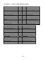
APPENDIX A – CONTACT ID REPORTING FORMAT....................................................................... 55
APPENDIX B - DIGITAL COMMUNICATOR CODE SHEET ............................................................ 56
FIGURES
FIGURE 1 - CONTROLLER HOOKUP............................................................................................................................................3
FIGURE 2 - OVERALL CONNECTIONS DIAGRAM ....................................................................................................................5
FIGURE 3 - TWO-WIRE FIRE ZONE CONNECTIONS .................................................................................................................7
FIGURE 4 - FOUR-WIRE FIRE ZONE CONNECTIONS ...............................................................................................................8
FIGURE 5 - RJ31X JACK CONNECTIONS...................................................................................................................................10
FIGURE 6 - CONSOLE CONNECTIONS ......................................................................................................................................13
FIGURE 7 - SOUNDER CONNECTIONS......................................................................................................................................15
FIGURE 8 - RESETTING CONTROLLER OUTPUTS..................................................................................................................16
FIGURE 9 - REMOTE KEYSWITCH CONNECTIONS ................................................................................................................18
FIGURE 10 - HAI THERMOSTAT CONNECTIONS ....................................................................................................................19
FIGURE 11 - TEMPERATURE / HUMIDITY SENSOR CONNECTIONS ..................................................................................21
FIGURE 12 - PESM CONNECTIONS ............................................................................................................................................22
FIGURE 13 - RS-232 CONNECTIONS...........................................................................................................................................24
FIGURE 14 - RS-485 CONNECTIONS...........................................................................................................................................24
FIGURE 15 - 24-HOUR STANDBY CONNECTIONS ..................................................................................................................53
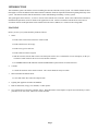
INTRODUCTION
This installation guide is intended as an aid to installing the Omni II Control & Security System. The installer should also have
thoroughly reviewed and understood the Omni II Owner's Manual, which has important information regarding final setup of the
system. This manual assumes that the installer has a basic understanding of installing a security system.
This guide applies to the 20A00-1, -4, and -12 versions of the Omni II series controller. Refer to the Underwriters Laboratories
Installation Requirements section for details in the application of each. Failure to install the Omni II and its accessories in
accordance with the UL Requirements in this manual and in the Owner's Manual, is a violation of the Listing Mark.
PLANNING
Before you start, your system should be planned as follows:
1.
Zones:
• Decide where each contact or detector will be located
• Decide which zone it will occupy
• Decide zone type for each zone
• Decide what area will be assigned
• With the customer, decide what text and voice descriptors will be used. Consult table of voice descriptors, so that you
can choose similar words for the text to avoid customer confusion.
• See SMOKE DETECTOR INSTALLATION GUIDELINES to plan locations for smoke detectors
2.
Consoles:
• Consult the customer on the console location. The console should be easily accessible.
3.
Interior Sounder and Outside Siren:
• Locate both where they cannot be tampered with.
4.
Lighting and Appliance Switches and Modules.
5.
Plan for thermostats, energy saver modules, or other options.
6.
Give consideration to where the controller will go. Remember that it needs a duplex receptacle not controlled by a switch,
preferably on its own circuit, within 5 feet of the controller.
Page 1
INSTALLATION
Go over your plan with your customer.
1.
Install the entire system. Refer to sections in this manual to see how to install various components.
2.
Follow the Power-Up and Checkout procedures.
3.
Explain the basics to the customer. Deliver all manuals and documentation.
4.
Follow up with your customer to keep them satisfied.
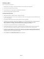
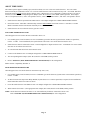
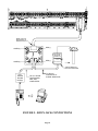
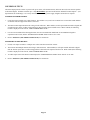
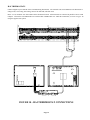
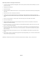
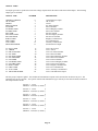
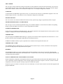
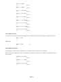
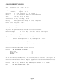
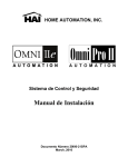
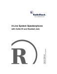
CONTROLLER HOOKUP
1.
When choosing a place to mount the controller, consider the following:
a. A duplex outlet, preferably on its own circuit, is required to be within 5 feet of the controller for the power transformer and
the X-10 Control Module.
b. The controller should be protected from weather, temperature extremes, and burglars.
2.
GROUND THE CONTROLLER "EARTH GND" TERMINAL TO A COLD WATER PIPE OR TO A 4-FOOT GROUND
ROD TO PRESERVE ITS BUILT-IN TRANSIENT PROTECTION. USE 14 GAUGE WIRE. TRANSIENT
PROTECTION WILL NOT WORK IF THE CONTROLLER IS NOT PROPERLY GROUNDED.
3.
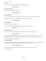
Connect the 24 VAC power transformer to the 24 VAC INPUT terminals.
4.
Connect the BLACK battery wire to the minus (-) terminal on the battery. DO NOT connect the red wire at this time. DO
NOT reverse the connections; the battery fuse will blow. Note that the unit will NOT START on the battery alone.
5.
Plug the X-10 Interface Module into the outlet above the transformer. Use the supplied 4-conductor modular telephone cable
to connect the module to the jack on the processor board. The red LED on the interface module should be on and will blink
off when the interface receives a signal from the controller.
6.
Refer to FIGURE 1 (CONTROLLER HOOKUP) for this configuration.
Page 2
1/4"
SPACING
BLACK WIRE TO RED WIRE TO +
YUASA NP7-12
OR EQUIVALENT
BATTERY
12V 7AH
THE BATTERY IS NON-POWER
LIMITED. THE BATTERY LEADS
MUST BE SEPERATED FROM
ALL OTHER POWER LIMITED/CLASS II
WIRING IN THE ENCLOSURE
BY AT LEAST 1/4"
COLD WATER PIPE
OR GROUND ROD
TWO - WAY
POWER LINE INTERFACE
24 VAC
40 VA
4 CONDUCTOR
14 GA. WIRE
POWER TRANSFORMER
REVERE
MODEL RT-2440SL
OR EQUIVALENT
GOUNDING METHOD MUST BE IN
ACCORDANCE WITH THE NATIONAL
ELECTRIC CODE, ANSI/NFPA 70.
FIGURE 1 - CONTROLLER HOOKUP
Page 3
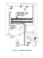
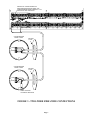
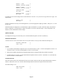
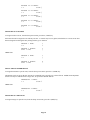
ABOUT SECURITY ZONES
Each of the 48 security zone inputs on an Omni II system may be configured as a burglary zone, a fire zone, a temperature zone,
or an auxiliary input. Zones 1-4, however, are the only inputs that can be used with 2-wire smoke detectors. Zones 9-16 are the
only inputs that can be configured as a PESM.
An external 1000-ohm end-of-line zone resistor is required for all zones unless the Setup item ZONE RESISTERS is set to "No".
If the Setup item ZONE RESISTORS is disabled, all zones other than Supervised Fire and Gas, will not use an end-of-line
resistor. In this configuration, all zone switches (other than Supervised Fire and Gas) must be normally closed (open for alarm).
If any zone requires a normally open (closed for alarm) switch (other than Supervised Fire and Gas), the Setup item ZONE
RESISTORS must be set to "Yes" and all zones will require and external 1000-ohm end-of-line resistor.
The zone type for each zone is selected through the Omni II SETUP menu or by using the PC ACCESS software.
The system supports a maximum zone resistance, excluding the end-of-line resistor, of 150 ohms. The default setting for ZONE
RESISTORS is "Yes". The default settings for all zone inputs on an Omni II controller are configured as Auxiliary inputs.
Omni II can be expanded to 48 zones by adding two 16 Zone Hardwire Expander Modules or one 16 Zone Hardware Expander
Module and one 16 Zone Wireless Receiver.
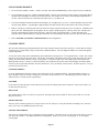
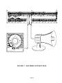
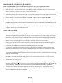
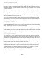
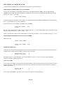
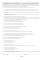
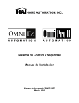
BURGLAR ZONE HOOKUPS
The Omni II system supports both normally open and normally closed switches. Most contacts designed for doors, windows,
motion detectors, glassbreak detectors and other security devices meet this requirement. An external 1000-ohm end-of-line
resistor must be used for all burglary zones if ZONE RESISTORS is set to "Yes".
1.
When using a normally open switch, a 1000-ohm end-of-line resistor must be in parallel with the zone being used. Maximum
loop resistance excluding end-of-line resistor should not exceed 150 ohms. ZONE RESISTORS must be set to "Yes".
2.
When using a normally closed switch, a 1000-ohm end-of-line resistor must be put in series with the zone being used if
ZONE RESISTORS are set to "Yes". If ZONE RESISTORS are set to "No", the 1000-ohm end-of-line resistor is not used.
Maximum loop resistance excluding end-of-line resistor should not exceed 150 ohms.
3.
Power motion detectors from AUXILIARY 12V.
4.
Unused zones may be left open, and should be left at the default setting of AUXILIARY zone types.
5.
When Zones 1-4 are configured to anything other than a Supervised Fire or Gas zone, the corresponding Zone Jumpers
(JP11-JP14) must be in the NRM (normal) position.
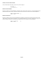
6.
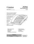
See FIGURE 2 (OVERALL CONNECTIONS DIAGRAM) for configurations of burglary zones.
Page 4
ZONE
ZONE
ZONE
(NO)
OUT
(NO)
SWITCH 12V
(OUTPUT)
WARNING
(NC)
(NC)
1K EOL
1K EOL
1K EOL
BURGLARY ZONES
SMK
SMK
JP11-14
JP11-14
COM
TO PREVENT RISK
FROM ELECTRIC SHOCK,
DE-ENERGIZE THIS
UNIT AND DISCONNECT
TELEPHONE LINES
BEFORE SERVICING.
NRM
12V
12V
4-WIRE
SMOKE
ZN
NRM
SWITCH 12V
(OUTPUT)
OUTPUT
ZN
1K
EOL
INPUT
ZN
ZONE (1-4)
1K
EOL
ZONE (1-4)
IN
4-WIRE FIRE ZONE
12V
2-WIRE
SMOKE
2-WIRE FIRE ZONE
NOTES:
1. SWITCH 12V, AUXILIARY 12V, CONSOLE, AND OUTPUTS 1-8 ARE INCLUDED IN THE TOTAL DEVICE LOAD, WHICH CANNOT EXCEED 1 AMP.
IN UL INSTALLATIONS, THE TOTAL DEVICE LOAD CANNOT EXCEED 250mA.
2. SOUNDERS CANNOT EXCEED 1 AMP, SPLIT BETWEEN INTERIOR AND EXTERIOR HORN OUTPUTS. IN UL INSTALLATIONS, SOUNDERS CANNOT EXCEED 350mA.
EARTH
GROUND
OUTPUT OUTPUT OUTPUT OUTPUT OUTPUT OUTPUT OUTPUT
SWITCHED
12 VDC
1A Max.
(See NOTE 1)
TRANSFORMER
24 VAC 40 VA
100 mA Max. (See NOTE 1)
AUXILIARY 12 VDC
1A Max.
(See NOTE 1)
CONSOLE(S)
INTERIOR
SOUNDER
(See NOTE 2)
ZONE
INPUT
ZONE
INPUT
ZONE
INPUT
ZONE
INPUT
ZONE
INPUT
ZONE
INPUT
ZONE
INPUT
ZONES 1-16 ARE CONFIGURABLE FOR BURGLARY, FIRE, TEMPERATURE, OR AUXILIARY.
2-WIRE SOMKE DETECTORS MAY ONLY BE CONNECTED TO ZONES 1-4.
CONNECT CABLE
TO CONTROLLER,
PLUG MODULAR
END INTO
RJ31X JACK
ALL CIRCUITS EXCEPT FOR THE BATTERY
ARE POWER-LIMITED (CLASS II)
EXTERIOR
SOUNDER
ZONE
INPUT
ZONE
INPUT
ZONE
INPUT
ZONE
INPUT
ZONE
INPUT
ZONE
INPUT
ZONE
INPUT
ZONE
INPUT
ONLY ZONES 9-16 MAY BE CONFIGURED AS ENERGY SAVER ZONES.
ONLY ZONE 16 MAY BE USED FOR HAI REMOTE CONTROL THERMOSTATS.
FIGURE 2 - OVERALL CONNECTIONS DIAGRAM
Page 5
HAI REMOTE
CONTROL
THERMOSTAT(S)
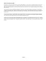
ABOUT FIRE ZONES
The Omni II system supports normally open (closed for alarm), two-wire or four-wire smoke detectors. Two-wire smoke
detectors can only be connected to Zones 1-4. Four-wire smoke detectors can be connected to any zone. An external 1000-ohm
end-of-line resistor must be used for all fire (and gas) zones. When Zones 1-4 are configured as a Supervised Fire (two-wire or
four-wire) or Gas zone, the corresponding Zone Jumpers (JP11-JP14) must be in the "SMK" (smoke) position. Zone Jumper
"JP11" corresponds to Zone 1, "JP12" corresponds to Zone 2, "JP13" corresponds to Zone 3, and "JP14" corresponds to Zone 4.
1.
Smoke detectors must be powered from SWITCH 12V or an Output configured as a SWITCHED POWER OUTPUT.
2.
End of line resistor: 1000 ohms. Maximum loop resistance EXCLUDING end of line resistor is a 150 ohms. Use HAI
Model 1503A0011 End of Line Resistor Assembly in UL Listed Installations.
3.
Smoke detectors are reset when the security system is armed.
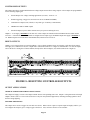
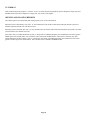
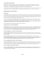
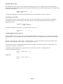
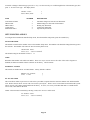
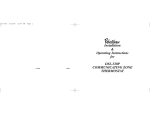
TWO-WIRE SMOKE DETECTORS
Omni II supports two-wire smoke detectors connected to Zones 1-4.
1.
Use normally open (closed for alarm) two-wire "SYSTEM" type smoke detectors (System Sensor 2100TS or equivalent),
rated 8 - 14 VDC. In UL installations, the System Sensor 2100 series 2-wire smoke detectors must be used.
2.
Smoke detectors must be connected to Zones 1-4 and configured as a Supervised Fire Zone. A maximum of 10 2-wire smoke
detectors can be connected to each zone.
3.
An external 1000-ohm end-of-line resistor must be used.
4.
Connect to the SWITCH 12V or an Output configured as a SWITCHED POWER OUTPUT.
5.
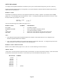
The corresponding Zone Jumpers (JP11-JP14) must be in the SMK (smoke) position.
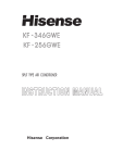
4.
Refer to FIGURE 3 (TWO-WIRE FIRE ZONE CONNECTIONS) for this configuration.
Smoke detector compatibility identifier: A
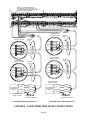
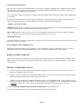
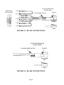
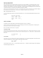
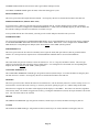
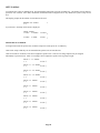
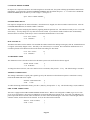
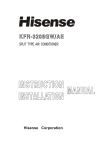
FOUR-WIRE SMOKE DETECTORS
Omni II supports four-wire smoke detectors connected to any zone (1-48).
1.
Use normally open (closed for alarm) four-wire "SYSTEM" type smoke detectors (System Sensor 2112/24TR or equivalent),
rated 8 - 14 VDC.
2.
An End of Line Power Supervision Relay Module (System Sensor A77-716B or equivalent) is required for UL installations.
Install 1000-ohm end-of-line resistor as shown.
3.
Power the smoke detector from SWITCH 12V or an Output configured as a SWITCHED POWER OUTPUT.
4.
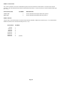
When connected to Zones 1-4, the appropriate Zone Jumper (JP11-JP14) must be in the SMK (smoke) position.
NOTE: Smoke detectors connected to Zones 1-4 are wired differently from those connected to Zones 5-48.
Refer to FIGURE 4 (FOUR-WIRE FIRE ZONE CONNECTIONS) for each configuration.
Page 6
WHEN Z1-Z4 IS CONFIGURED AS A
SUPERVISED FIRE OR GAS ZONE, THE
CORRESPONDING ZONE JUMPERS J11-J14
MUST BE IN "SMK" POSISTION
SYSTEM SENSOR
MODEL 2100TS
BOTTOM
PLATE
ZONE
ZONE
SYSTEM SENSOR
MODEL 2100TS
BOTTOM
PLATE
ZONE
ZONE
MODEL 1503A0011
1K OHM EOL RESISTOR
FIGURE 3 - TWO-WIRE FIRE ZONE CONNECTIONS
Page 7
WHEN Z1-Z4 IS CONFIGURED AS A
SUPERVISED FIRE OR GAS ZONE, THE
CORRESPONDING ZONE JUMPERS J11-J14
MUST BE IN "SMK" POSISTION
GREEN
YELLOW
BLACK
RED
SYSTEM SENSOR
MODEL 2112/24TR
ZONE
YELLOW
ZONE
GREEN
+12V
RED
GND
BLACK
BLACK
RED
YELLOW
GREEN
SYSTEM SENSOR
MODEL 2112/24TR
BOTTOM
PLATE
ZONE
YELLOW
ZONE
GREEN
+12V
RED
GND
BLACK
SYSTEM SENSOR
MODEL 2112/24TR
SYSTEM SENSOR
MODEL 2112/24TR
BOTTOM
PLATE
BOTTOM
PLATE
BOTTOM
PLATE
ZONE
YELLOW
GREEN
ZONE
YELLOW
ZONE
ZONE
GREEN
+12V
RED
+12V
RED
GND
BLACK
GND
BLACK
BLACK
BLACK
RED
RED
VIOLET
GREEN
VIOLET
YELLOW
SYSTEM SENSOR
MODEL A77-716B
EOL POWER
SUPERVISION
RELAY
ZONE POWER
EOL POWER
SUPERVISION
RELAY
ZONE POWER
SYSTEM SENSOR
MODEL A77-716B
BLACK
BLACK
RED
RED
VIOLET
GREEN
VIOLET
YELLOW
MODEL 1503A0011
1K OHM EOL RESISTOR
MODEL 1503A0011
1K OHM EOL RESISTOR
FOUR-WIRE DETECTORS ON ZONES 1-4
FOUR-WIRE DETECTORS ON ZONES 5-16
FIGURE 4 - FOUR-WIRE FIRE ZONE CONNECTIONS
Page 8
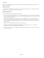
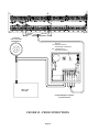
TELEPHONE CONNECTIONS
1.
If an RJ31X jack has been supplied by the telephone company, it is probably wired correctly and the controller can be
connected by plugging the supplied 8 conductor telephone cable into the RJ31X jack. The other end of the cable is spaded.
The green, red, brown, and gray wires must be connected to the controller at the designated terminals under the section of the
board marked 'PHONE'.
2.
If required, install the supplied RJ31X jack as shown in the following diagram. The polarity must be correct for proper
operation of the phone access feature.
3.
IT IS IMPERATIVE THAT THE PHONE LINE COMING INTO THE HOUSE BE CONNECTED TO A GROUNDED
SURGE ARRESTOR OUTSIDE THE PREMISES. IT IS THE RESPONSIBILITY OF THE TELEPHONE COMPANY
TO PROVIDE THIS SURGE ARRESTOR.
4.
INSPECT THE INCOMING PHONE LINES. THE FIRST THING THAT THEY SHOULD GO TO IS A SMALL BOX
ON THE OUTSIDE OF THE PREMISES. THERE SHOULD BE A HEAVY GROUND WIRE COMING FROM THIS
BOX GOING TO A COLD WATER PIPE OR A SEPARATE GROUNDING ROD.
5.
IF THERE IS NO SURGE ARRESTOR OR IF THE GROUND WIRE IS MISSING, HAVE THE CUSTOMER INSIST
THAT THE TELEPHONE COMPANY INSTALL ONE FOR THE SAFETY OF THE CUSTOMER.
6.
WHEN WIRING A RJ31X JACK, MAKE SURE THAT THE INCOMING PHONE LINES GO TO THE TELEPHONE
COMPANY SURGE ARRESTOR BEFORE THEY GO TO THE RJ31X JACK.
7.
When the RJ31X is installed as shown, locate the green, red, brown, and gray spaded wires from the 8 conductor phone cable
and connect to the section on the Omni II controller marked 'PHONE'. Plug the modular end of the cable into the RJ31X
jack. If necessary, bend the tab up on the plug to ensure a tight fit that will not fall out.
8.
Verify the following if you have trouble during check out: With the system running, the RJ31X jack properly connected and
all phones on-hook (hung up), the PHONE LED, located in the upper left corner of the controller, should be OFF. If it is on,
reverse the RED and GREEN wires to both the house phones and the telephone company wires at the RJ31X jack. When the
receiver is picked up on any phone, the PHONE LED will come on. When the phone line rings, the PHONE LED will light.
9.
If the Omni II is accessed on an in house telephone, the Omni II will disconnect the phones from the phone company lines
and supply its own talk voltage to the phones. The PHONE LED will be on in this case.
10. Refer to FIGURE 5 (RJ31X JACK CONNECTIONS) for this configuration.
Page 9
RED(-)
GREEN(+)
TELEPHONE
NETWORK
INTERFACE
RED(-)
GREEN(+)
CUSTOMER
ACCESS
SURGE ARRESTOR
SURGE ARRESTOR
MUST BE GROUNDED!
RJ11
HOUSE
PHONE
JACK(S)
TO ALL HOUSE
TELEPHONES,
PBX, AND
COMPUTERS
TO TELCO
INTERFACE AT
SURGE ARRESTOR
FIGURE 5 - RJ31X JACK CONNECTIONS
Page 10
GRAY
BROWN
RED
GREEN
BEND TAB UP IF
NECESSARY TO
ENSURE TIGHT FIT
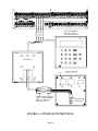
LCD CONSOLE HOOKUP
1.
8 LCD Consoles (Models 11A00-1, 11A00-2, 11A00-9, and 15A00) MAXIMUM per system, subject to power availability.
2.
Use 4-conductor 22-gage wire, 1000 feet maximum length. Consoles can be homerun or daisy chained. This length shall be
divided by the total number of consoles at the end of the run. For example, for 8 consoles, the maximum length reduces to
125 feet. All LCD Consoles are connected to the same 4 wires, +12, GND, A, B.
3.
The console should be mounted so that the LCD display is at or slightly above eye level. Consoles should be kept out of the
reach of young children. A good height is approximately 58 inches from the floor to the bottom of the console enclosure.
4.
Remove console face from back plate (slots on bottom of console will release back plate, use a screwdriver). Mount the back
plate to the wall. Mounting holes are designed to fit on a single or double gang box, or directly to the wall. Pull the wires
from the wall through the opening in the back plate. Splice the wires to the supplied cable. Connect the cable to the
connector on the console board (J1). Snap the console face on to the back plate. Remove protective film from the LCD lens.
5.
Refer to FIGURE 6 (CONSOLE CONNECTIONS) for this configuration.
CONSOLE SETUP
The console has different operating options that can be setup from the console to the user's preference. If more than one console
is being used, it is required that you give each console a different address. You can change the address of a console through the
console setup mode.
To enter the console setup mode, simultaneously press and hold the 4 and up arrow (!) for approximately 1 second. The console
will beep 5 times and enter the setup mode. The top line of the display will indicate what you are doing, followed by the current
setting. The bottom line will show a menu of your options. To the lower right corner of the display is the direction arrow(s).
Where possible, the up (↑), down (↓), and two-headed (↕) arrow characters are shown on the console display to indicate which
arrow keys may be pressed at that time. Press the down arrow (") key to advance to the next item. Press the up arrow (!) key to
go back to the previous item.
CONSOLE ADDRESS
If you are installing more than one console, each console must be set to a different address. The default address setting is (1) this is adequate if only one console is being used. The choices at the bottom are 1-16. When making your choice, choose an
address between 1-8, then press the # (pound) key.
SOUNDER
If you wish not to hear the beeper in the console for any reason, the sounder option can be turned off. Select (0) for OFF or (1)
for ON, then press the # key.
KEY CLICK
The sounder makes a click every time a key is pressed. This option may also be turned off. Select (0) for OFF or (1) for ON,
then press the # key.
KEY BACKLIGHT
The keys on the console keypad are lit. The keys can be never lit, always lit, or only lit when the LCD display is lit. Select (0)
OFF, (1) for ON, or (2) TIMED, then press the # key.
VIEWING ADJUSTMENT
This option is an adjustment for the viewing angle of the LCD display. This has been set to its best value at the factory, however,
you may wish to tweak it. The display has 20 levels of adjustment. Select (1) for a lower viewing angle, or (2) for a higher
viewing angle.
Page 11
LANGUAGE
This option is to display the 'console setup' text on the LCD display in English, French, Italian, or Spanish. Select one of the
languages, then press the # key.
EXIT SETUP MODE
To exit Setup Mode, press and hold the 4 and up arrow (!) keys simultaneously for about 1 second. The console will return to
normal operation. You may need to press (*) to restore the display.
CONSOLE SELF TEST
Use the self test mode to verify the proper operation of the console.
1.
Disconnect the console from the controller. Connect +12 and GND terminals to a 12-volt source (or a fresh 9-volt transistor
battery.) The console beeper will beep twice per second, the LCD backlight and the keypad key will be lit, and the LCD will
display "NO CONTROLLER DATA".
2.
Simultaneously press and hold the 7 and the down arrow (") keys for approximately 3 seconds. The beeper will beep 5
times, the LCD backlight and keypad backlight will turn off, and the display will clear. The LED at the top right corner of
the console will start to cycle through its different colors (red, green, yellow, then turns off). At the end of each cycle the
beeper will beep once.
3.
Press any key. The LCD backlight and the keypad key backlight will turn on.
4.
Press the keys in the following order and verify that the appropriate character fills the screen. 0 - 9, *, #, AWAY (A),
NIGHT (B), DAY (C), OFF (D), ! (filled blocks), and " (blanks).
5.
If this is successful, the console is good. Simultaneously press and hold the 7 and down arrow (") keys to exit the self test
mode or disconnect power.
Page 12
GREEN
YELLOW
RED
BLACK
FOR MODEL NUMBERS
SEE NOTE 1 UNDER
"LCD CONSOLE HOOKUP"
CONSOLE FACE
(SNAPS ON TO BOTTOM PLATE)
BOTTOM PLATE
CONSOLE PC BOARD
(MOUNTED TO CONSOLE FACE)
YELLOW
GREEN
RED
BLACK
CONNECT ENDS OF SUPPLIED
CABLE TO CORRESPONDING
ENDS OF 4 - WIRE CABLE
FROM CONTROLLER
FIGURE 6 - CONSOLE CONNECTIONS
Page 13
SUPPLIED CABLE
(PLUGS INTO J1)
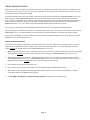
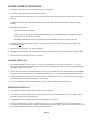
SOUNDER OUTPUTS
The Horn Output provides 12VDC to power bells, piezo sirens, self-contained sirens, and siren drivers (do not connect speakers
to the Horn Output). Sounders can draw up to 1 amp MAXIMUM, split between the Interior and Exterior Horn Outputs - (See
Specifications for UL Ratings). Use a relay connected to an auxiliary power supply if higher current draw is required.
INTERIOR SOUNDER HOOKUP
1.
Locate the interior sounder in a central location. The sounder is very loud. Do not install it in a room where small children
or animals could be trapped if the alarm is activated.
2.
The Interior Horn Output monitors the wiring to bells and sirens. When enabled, it will report trouble and make a digital dial
out when an open, short, or other wiring problem is detected in the supervised bell circuit. When violated, the following
trouble is displayed on the console, "FIRE TAMPER TRBL NOW".
3.
For UL Listed residential fire alarm applications, the UL Listed Wheelock Model MT-12/24-R Multitone Signal or
equivalent must be used, and the "SUPERVISE INT SNDR" feature must be set to "ON".
4.
Refer to FIGURE 7 (SOUNDER CONNECTION) for connections.
EXTERIOR SOUNDER HOOKUP
1.
If used, wire tamper switches to a tamper zone with a 1000-ohm end-of-line resistor.
2.
The Exterior Horn Output monitors the wiring to bells and sirens. When enabled, it will report trouble and make a digital
dial out when an open, short, or other wiring problem is detected in the supervised bell circuit. When violated, the following
trouble is displayed on the console, "FIRE TAMPER TRBL NOW".
3.
To enable supervision of the Exterior Horn Output, the "SUPERVISE EXT SNDR" feature must be set to "ON".
4.
Refer to FIGURE 7 (SOUNDER CONNECTION) for connections.
Page 14
RED
BLACK
RED
FIGURE 7 - SOUNDER CONNECTIONS
Page 15
CONTROLLER OUTPUTS
The Omni II provides 8 programmable hardwired voltage outputs and two horn voltage outputs. These outputs are programmable
for the following output types:
•
General Purpose low voltage switching applications (12 VDC) - Units 65 - 72
•
Sounder triggering (a trigger for siren and voice drivers for BURG and FIRE)
•
Communicator outputs (radio, cellular, or any other type of auxiliary communicator)
•
'ARMED' and 'OK TO ARM' outputs
•
Switched Output (to power smoke detectors and cycle power to latching devices)
Outputs 1 - 8 can supply a maximum of 100 mA each. These outputs are included in the total DEVICES load, which cannot
exceed 1A. If the Interior or Exterior Sounder is configured to an Output Type, the HORN outputs can supply a maximum of
1A. HORN outputs are included in the total HORNS load, which can not exceed 1A.
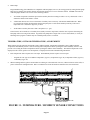
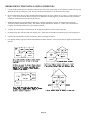
RESET OUTPUTS
Outputs 1-8 are protected from an overload condition. If an overload condition occurs on an output, it will shut off (the output
will supply 0V). When this occurs, the "Output Fault" (D26) LED (marked "A" if Figure 8) will illuminate. To reset the output,
remove the device causing the overload condition, then press the "Reset Outputs" (S1) Switch (marked "B" if Figure 8).
A
B
FIGURE 8 - RESETTING CONTROLLER OUTPUTS
OUTPUT APPLICATIONS
GENERAL PURPOSE SWITCHING APPLICATIONS
This output will supply 12 VDC to the output terminal when its corresponding unit is ON. Output 1 is designated Unit 65 through
Output 8 which is Unit 72. This can be used to drive relays for many different applications, including switching sprinkler valves
and low-voltage lighting.
SOUNDER TRIGGERING
This output can be used as a trigger for siren and voice drivers. When a driver requires a separate input for burglary and fire, you
can configure this output to give a voltage trigger to the driver. Also, each area can have its own sounder.
Page 16
COMMUNICATOR OUTPUTS
This output can be used for radio communications or any other type of auxiliary communications to augment the built-in digital
and voice dialers. Any communications device can be used with the Omni II, provided that it is powered by 12 VDC, has 12
VDC triggered inputs, and has 2 (or more) channels.
The 'Communicator' outputs are activated 3 seconds before the Omni II dialer begins to dial either using its built-in digital dialer
or voice dialer.
The following events will activate the BURG output: Burglar alarms (including panic zones), Auxiliary emergencies, Police
emergencies, and Duress alarms. Fire alarms and the fire emergencies will activate the FIRE output.
"ARMED" AND "OK TO ARM"
ARMED: When the system is armed in any of the security modes (AWAY, NIGHT, DAY, or VACATION), this output is active.
It is typically used to activate a red LED to indicate that the system is 'armed'.
OK TO ARM: When all security zones are secure, no zones are bypassed, and the system is in the 'OFF' mode, this output is
active. It is typically used to activate a green LED to indicate that the system is 'ok to arm'.
SWITCHED OUTPUT
This output is used to cycle power to latching devices when the system is armed. This output will reset the smoke detectors when
the system is armed after an alarm.
HAI COMMUNICATING THERMOSTATS
When HAI RC-Series thermostats are used, Output 8 is used to communicate with up to 4 thermostats. There is no need to
configure this output when used with HAI thermostats. It may be left at the default setting of "General Purpose".
HOME CONTROL MODULES
Install X-10 or compatible modules EXACTLY as described in the instructions that come with each module. Watch the load
ratings and types of load allowed. The Omni II is designed to send signals to any device compatible with the X-10 powerline
carrier protocol
REMOTE ARM/DISARM SWITCH
1.
If desired, a remote keyswitch, keypad, or hidden arm/disarm toggle switch can be connected to the system. The device
should have a momentary close type switch.
2.
Configure one of the zone inputs as a KEYSWITCH INPUT zone. A closure of the switch contacts will toggle the arming
mode between OFF and AWAY (Entry and Exit delays are still active).
3.
Configure one of the outputs as an "ARMED" and another output as an "OK TO ARM" output. These outputs are used to
activate a red or a green LED based on the state of the alarm system. The "ARMED" and "OK TO ARM" outputs can supply
a maximum of 100 mA each. These outputs are included in the total DEVICES load, which cannot exceed 1 A.
4.
Refer to FIGURE 9 (REMOTE KEYSWITCH CONNECTION) for this configuration.
NOTE: In UL Listed Installations, the Listed Ademco Model 9789 keyswitch shall be used.
Page 17
GREEN
YELLOW
RED
1KEOLRESISTOR
BLACK
YELLOW
GREEN
RED
+
GREEN
+
BLACK
RED
MOMENTARY CONTACT
KEYSWITCH
FIGURE 9 - REMOTE KEYSWITCH CONNECTIONS
Page 18
HAI THERMOSTATS
Omni II supports up to 4 HAI RC-Series Communicating Thermostats. The controller can send commands to the thermostat to
change mode, cool setting, heat setting, status of fan and hold, and other items.
FIGURE 10 - HAI THERMOSTAT CONNECTIONS
Page 19
YELLOW
GREEN
BLACK
Run a 3 (or 4) conductor wire from Omni II to the thermostat location. All thermostats are connected in parallel to Zone 16 and
Output 8. Connect the red COMM cable wire with the black COMM cable wire. Make the connections (as shown in Figure 10)
using the supplied wire splices.
PROGRAMMABLE ENERGY SAVER MODULES
NOTE: Programmable Energy Saver Modules must be connected to zones 9-16 on the Omni II controller.
1.
Omni II can support up to 8 Programmable Energy Saver Modules (PESM). Each PESM requires one security zone input
and one controller output. The zone input corresponds to the controller output (Zone 9 and Output 1 through Zone 16 and
Output 8, respectively). If Zone 9 is used, Output 1 must be used as its pair.
2.
When setup as an Energy Saver Zone Type (Type 80), the zone and unit (output) is used as a pair to read in temperature and
control the setback temperature of the house. Only zones 9-16 may be configured as an Energy Saver zone.
3.
Run a 4-conductor wire from the Omni II controller to each PESM. Connect as shown in FIGURE 12 (PESM
CONNECTIONS).
4.
The PESM should be mounted on an interior wall, preferably close to the HVAC thermostat. Run a 2-conductor wire from
the PESM to the thermostat. Connect the PESM between the RED wire going to the thermostat and the RED terminal on the
thermostat.
5.
Program the zone type for PESMs as a Type 80, Energy Saver. It may also be programmed as a Temperature (Type 82), or
Temperature Alarm (Type 83) for special applications.
NOTES ON HVAC SYSTEMS
1.
Description of the PESM
The PESM is a temperature sensor and control relay in a small enclosure that mounts near a central heating, ventilation, and
air conditioning (HVAC) system thermostat. The PESM allows the automation system to read the temperature of the area
that the HVAC system controls. The relay in the PESM is used to break the 24V RED wire between the thermostat and the
HVAC system. When the automation system is in setback mode and the actual temperature is between the LO and HI
setpoints, the relay energizes to break the 24V red wire; hence, the HVAC system will no longer operate.
In heating season, when the actual temperature falls below the LOW setpoint, the automation system turns the relay in the
PESM off, thus restoring power to the thermostat, allowing the thermostat to heat as it normally would under the control of
the thermostat. The PESM will cycle the thermostat on and off to maintain the LOW setpoint.
In cooling season, when the actual temperature rises above the HI setpoint, the automation system turns the relay in the
PESM off and the thermostat will cool as it normally would under the control of the thermostat. The PESM will cycle the
thermostat on and off to maintain the HI setpoint.
The Red LED on the PESM will illuminate when the PESM is overriding the thermostat. The Red LED will be off when the
thermostat is working normally.
If the PESM is disconnected from the automation system, the relay will not energize and the HVAC system will operate
normally, under the control of the thermostat.
2.
Standard Heating and Cooling Systems
The PESM is compatible with all mechanical thermostats. Recommended thermostats are simple, round Honeywell T-87
thermostats. For automatic switch-over from heat to cool, consider a Honeywell T-874 (mechanical) or an Enerstat DSL-300
(electronic) thermostat, although any other mechanical thermostat from White Rodgers, Robertshaw, etc. will work.
3.
The PESM is also compatible with electronic thermostats that run totally on battery power. Some examples of battery
powered thermostats are Maple Chase Saverstat (Mgf. #0960-1), White-Rodgers Digital Programmable Thermostat (Mfg.
#1F80-51), and Honeywell Chronotherm Thermostat.
Page 20
4.
Heat Pumps
Programmable Energy Saver Modules are compatible with heat pumps, however, the savings gained by setting the heat pump
back may be erased by the auxiliary heaters when the heat pump tries to recover from the setback. A PESM will work best
with heat pumps that have one or more of the following features:
a.
An outdoor temperature switch that prevents the auxiliary heat from coming on unless it is very cold outside. This is
sometimes called a "heat balance" switch.
b.
A thermostat that uses rate of rise to determine if auxiliary heat is necessary: The Enerstat Model DSL-450. When
recovering from setback, the thermostat runs the heat pump first. It will run the auxiliary heat only if the rate of
temperature rise is less than 6 degrees F. per hour.
c.
An alternative auxiliary heat source that is inexpensive (i.e. gas).
These features will avoid the use of auxiliary heat (usually an electric strip heater) which is more expensive than using the
heat pump when recovering from setback. In general, heat pumps take a longer time to recover from setback, so it may be
advantageous to program a setback only for extended periods, such as a vacation.
TEMPERATURE, OUTDOOR TEMPERATURE, AND HUMIDITY
When connected to the controller, the Model 31A00-1 Indoor/Outdoor Temperature and Model 31A00-2 Indoor/Outdoor
Temperature and Humidity Sensor is used for sensing indoor temperature and/or reporting the relative humidity from 0 to 100
percent or for sensing the outdoor temperature and/or reporting the outdoor relative humidity. The outdoor temperature can be
displayed on the console, spoken over the telephone, or displayed on an HAI Communicating Thermostat.
1.
Each Temperature Sensor requires one zone input. Each Humidity Sensor requires one zone input.
-
2.
Program the zone type as an Outdoor Temperature (Type 81), Temperature (Type 82), Temperature Alarm (Type 83),
or Humidity (Type 84).
When mounting outdoors, plan to mount under an overhang or to the underside of an eave, otherwise known as the soffet, to
protect it from direct sunlight and rain. Run a 4-conductor wire from the Omni II controller to the selected location.
BLACK
RED
YELLOW
GREEN
12V GND H T
RED
BLACK
GREEN
YELLOW
INDOOR / OUTDOOR TEMPERATURE
AND HUMIDITY SENSOR
FIGURE 11 - TEMPERATURE / HUMIDITY SENSOR CONNECTIONS
Page 21
BLACK
RED
YELLOW
GREEN
EXISTING
LOW VOLTAGE
THERMOSTAT
RED LED
ON - ENERGY SAVER IS
OVERRIDING THERMOSTAT
BLACK
YELLOW
RED
GREEN
OFF - THERMOSTAT IS
WORKING NORMALLY
HEAT / AIR
SYSTEM
PROGRAMMABLE ENERGY
SAVER MODULE
FIGURE 12 - PESM CONNECTIONS
Page 22
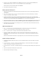
BUILT-IN SERIAL PORT
Omni II has a serial port (J1) built onto the controller (labeled SERIAL 1). The interface is a modular connector located in the
upper left corner of the controller. It uses either the Omni-Link or Pro-Link Protocol for connections to the Internet via HAI
Web-Link II, personal computers, and other optional interfaces like touchscreens, voice recognition, lighting controls, and home
theater controls.
The serial interface supports both RS-232 and RS-485 connections. RS-232 is the standard for connections to most personal
computers and related systems. RS-485 can support greater wiring distances. The default setting is RS-232. To select RS-485,
move the interface jumper (JP1) from the 232 to the 485 position. The jumper (JP1) is located below the modular serial port
connector (J1).
To access the serial port, use the HAI Model 21A05-2 Serial Cable Kit. Plug one end of the cable into the modular serial port
connector on the controller. Plug the other end into the Model 21A05-1 Communication Cable Adaptor (modular to DB-9 RS232), which connects the Omni II serial port to the computer's DB-9 RS-232 port.
To make your own serial cable, follow the diagrams (Figure 13 and Figure 14). When making connections, be sure to correctly
orient the cable as shown (with the tab on the modular cable facing up, make sure that the Yellow wire is at the top). Connect the
Yellow, Green, Red, and Black wires to the DB-9 connector as shown. Also, connect Pins 1, 4, and 6 together and Pins 7 and 8
together.
Page 23
4 POSITION MODULAR
PHONE CABLE
7 RTS
DB9-FEMALE
BOTTOM VIEW
- YELLOW WIRE ON TOP -
8 CTS
3 TX
6
7
8
9
YELLOW
GREEN
RED
BLACK
2 RX
1
2
3
4
5
- TAB UP -
1 DCD
5 GND
TOP
4 DTR
6 DSR
SIDE
FIGURE 13 - RS-232 CONNECTIONS
4 POSITION MODULAR
PHONE CABLE
- YELLOW WIRE ON TOP -
A
B
- TAB UP -
YELLOW
GREEN
TOP
SIDE
FIGURE 14 - RS-485 CONNECTIONS
Page 24
SYSTEM POWER UP PROCEDURE
1.
Carefully review hookups to the zones, grounds, sounders, and consoles.
2.
Disconnect 1 lead of both the interior and exterior sounders.
NOTE: Follow this power up procedure to verify proper operation of the power supply, battery charger, and low voltage cut
out relay.
3.
The positive lead to the battery should be disconnected at this time. Make sure that the red battery wire is not touching
anything.
4.
Plug in the power transformer.
-
The AC ON LED should illuminate.
-
Within one minute, the STATUS LED should begin blinking at a rate of 1 blink per second. This indicates that the
Omni II processor and software are working.
-
The PHONE LED should be OFF (if all telephones are on-hook and the RJ31X jack is properly connected.
5.
Unplug the power transformer to kill the system. Connect the red battery wire to the + (positive) battery terminal. The
system should not start.
6.
Plug in the power transformer. The system should start.
7.
Unplug the power transformer. The system should continue to run on the battery (the STATUS LED will continue to flash).
8.
Plug the transformer back in and secure it to the outlet.
CONSOLE CHECK OUT
1.
The console(s) should be operating. Press ' * ' to silence the trouble beeper if it is beeping. Press OFF, 1, 1, 1, 1 (or the
current User code) if the alarm is tripped. If the consoles are not operating properly, make sure that no two consoles have the
same address, and check the wiring.
2.
With all doors and windows closed and all motion detectors secure, the bottom line of the display should read SYSTEM OK.
If there are any trouble indications that occurred during installation, press ' * ' to acknowledge them and silence the beeper.
3.
Set the time and date by pressing the 9 key. Enter the Master Code, then press the 2 key. Enter the time on the keypad, then
the DATE (enter date as 6 characters: January 1, 00 as 010100).
4.
The console should now show the time and date on the top line and "SYSTEM OK" on the bottom line.
TELEPHONE CHECK OUT
1.
Verify that the Telephone Company surge arrestor is properly grounded.
2.
Verify that the incoming telephone lines are run to the surge arrestor first, then from the surge arrestor to the RJ31X jack,
then from the RJ31X jack to the house phones.
3.
The PHONE LED, on the controller, should be off when the phones are hung up.
4.
Pick up an in-house phone, wait about 1 second, then press the ' # ' key. You should hear the Voice menu on the phone. If
not, check to see that the RJ31X jack is properly wired and connected to the controller. There should be no interference from
the Telephone Company while the menu is being read over the phone.
Page 25
5.
Record the owner's NAME and ADDRESS in the ADDRESS speech memory as shown in SETUP ADDRESS in the
OWNER'S MANUAL (Press 8, 9, then 1111 or the current Master code to record the address).
NOTE: DO NOT record any TOUCH TONES in the ADDRESS!!
6.
Check that all in-house phones are working.
BURGLAR ZONE CHECK OUT
1.
With all doors and windows closed and all motion detectors and security devices secure, the console display should read
"SYSTEM OK".
2.
If any zones are abnormal, check your wiring. If the battery indication is low, make sure that the battery is connected
securely. Give the battery a chance to charge.
3.
From the top-level display, have a partner go around the house and trip each sensor one at a time. The display should
indicate the correct zone "NOT RDY" when the zone is tripped, then return to "SYSTEM OK" when the zone is secured. Be
sure that the zone type indicated (ENTRY/EXIT, PERIMETER, ETC.) is correct for the zone being tested.
4.
If the zone being checked is armed, (i.e. PANIC or TAMPER type, which is always armed) the alarm will be activated. Press
OFF and 1111 or the current User code to silence the alarm, or bypass the PANIC and TAMPER zone(s) before you start.
5.
Reconnect the sirens. Be sure that no one is standing near a siren. Activate the alarm, and ensure that both the inside and,
after a delay, outside sirens activate.
FIRE ZONE CHECK OUT
1. Press ' * ' to return the console to the SYSTEM OK indication. Check the fire zone per the sensor manufacturer's
instructions. The fire alarm should be activated (pulsing interior sounder, exterior siren).
2.
Press ' * ' to silence the alarm. The display will still indicate that the FIRE ZONE is in alarm.
3.
Press DAY or NIGHT or AWAY and the User code to arm the system, then OFF and the User code to disarm. This
arm/disarm cycle will reset the smoke detector. If the cause for alarm (i.e. smoke) has cleared, the display will return to
SYSTEM OK.
NOTE: Be sure that the DIAL OUT DELAY is long enough so that you can cancel the alarm before the system dials out.
HOME CONTROL CHECKOUT
1.
Confirm that the HOUSE CODE on the Omni II is set to the same HOUSE CODE set on all of the modules (See SETUP
CONTROL).
2.
On the console press 4, 1 (ALL ON). All lamp type modules should go on. Note that some modules, such as appliance
modules, voltage outputs, and flags do not respond to ALL ON.
3.
On the console press 4, 2 (ALL OFF). All modules should go off. Note that voltage outputs and flags do not respond to ALL
OFF.
4.
Operate each unit number individually and verify that it works.
5.
Ensure that all inputs and outputs are working.
Page 26
CUSTOMER CHECKOUT
After you have completed the system check out and everything works, be sure that the customer knows how to:
1.
Disarm/silence the system (OFF, 1111 or current User code). HAVE THE CUSTOMER PRACTICE!
2.
Change the codes.
3.
Get the menu over the in-house phones.
You should also:
4.
Demonstrate arming and disarming.
5.
Demonstrate home control.
6.
Demonstrate setup and programming.
7.
Show him/her how to program the dial out numbers.
8.
Deliver the Owner's Manual.
9.
If the customer has subscribed to a central monitoring service, this should be explained to him/her.
IN CASE OF TROUBLE
CONSOLES
If you experience trouble that seems to be with a console, try disconnecting the console and running the console self test as
described under CONSOLE HOOKUPS in this manual. If the console does not run the self-test properly, it should be returned to
HAI for repair.
"NO CONTROLLER DATA" or erratic operation of the LCD display could be a result of: A and B terminals connected
backwards, poorly, or 2 or more consoles have the same address.
CONTROLLER
Check the AC ON (bottom) LED. If it is not lit, check for 24 VAC at the transformer connections.
Check the STATUS (top) LED on the controller board. It should be blinking once per second, indicating the proper operation of
the microprocessor and memory. If not, try powering the system down by disconnect the power transformer and battery, then
reconnect both. The status light should begin blinking.
If the AC ON LED is on and the STATUS light is still not blinking, check the AUX +12 V with a DC voltmeter. It should be
13.7 volts. If not, make sure that there isn't too much load on the system. Disconnect all loads. If the STATUS LED still won't
blink, there is a problem with the controller board and it must be returned to HAI for repair.
Phone line problems, or problems with the Omni II voice are usually the result of the RJ31X jack being improperly wired. Check
RJ31X jack wiring and polarity carefully, as described in TELEPHONE CONNECTIONS.
In the event that the controller is found defective, the controller board can be removed without disconnecting the entire wiring
from their terminals. The terminal strips can be removed from the controller board. Then the controller (or processor board) can
be repaired and reinstalled easily.
Page 27
Follow this procedure for removing the controller board:
1.
If possible, upload the programs and configuration. (This will not be possible if the status LED isn't flashing or if you can't
get the voice to work.)
2.
Unplug the power transformer.
3.
Disconnect the battery
4.
Disconnect the RJ31X modular cable at the jack!! If you only disconnect it at the Omni II controller only, the house phones
won't work.
5.
Disconnect the X-10 cable. Disconnect the serial cable.
6.
Carefully remove the four terminal strips from the controller board. Gently push down on terminal strip retention clips.
These clips are located on either end of the strip and 2 in the middle. Slowly pull strip away from terminal block socket and
secure.
7.
Remove 9 screws and washers; 3 on the top edge, 3 on the bottom edge, and 3 in the middle of the controller.
8.
Remove the controller board.
9.
Wrap the controller board with protective material and pack carefully. HAI will not be responsible for returned items
damaged due to inadequate packaging.
10. Call Home Automation, Inc. with the serial number for a Return Authorization number to help us track your return. Write
the R. A. # on the outside of the package.
11. Return the controller to Home Automation, Inc. Please include your return address, any special shipping instructions and
daytime phone number so that we can reach you if we have any questions. Also include a brief description of the problem
that you are having.
12. INSTALLATION: follow the removal process in reverse. Follow the POWER UP and CHECK OUT procedures in this
manual.
13. NOTE: When a controller is returned from being repaired, all setup and programming is lost. The board is returned with the
factory default setup and programming.
FOR HELP: Call HAI between the hours of 9:00 AM and 5:00 PM Central time, Monday - Friday, at (800) 229-7256.
Page 28
DIGITAL COMMUNICATOR
The Omni II digital communicator can use Contact ID, or Standard 4/2 or 3/1, (20 pps, 1800 Hz data, 2300 Hz handshake), or (10
pps, 1900 Hz data, 1400 Hz handshake), dual round compared format. Any central station with modern equipment can receive
these formats. Compatible receivers are Ademco, Radionics, Osborne-Hoffman, Linear, FBI, and Silent Knight. It is up to the
installer to verify compatibility. At the time of installation, the installer is required to verify compatibility and phone line seizure
of the Digital Communicator.
If the digital dialer does not get a handshake signal from the central station 45 seconds after it begins dialing, it hangs up and tries
again. The dialer will try the FIRST PHONE NUMBER 5 times, then go to the SECOND PHONE NUMBER and try that 5
times. After that, the system will indicate COMMUNICATIONS FAILURE on the console display and the digital communicator
will not try again until another reportable event occurs.
The digital communicator will not dial out until the DIAL OUT DELAY has expired. If the alarm is canceled prior to the
expiration of the DIAL OUT DELAY, no transmission will take place. After the DIAL OUT DELAY has expired, though, all
alarm trips will be transmitted followed by a CANCEL code.
When the digital communicator is used, all voice dial outs will be delayed for five minutes after the expiration of the dial out
delay to allow time for the central station to call the premises after an alarm code has been sent. If the digital communicator is
unable to successfully communicate with the central station, the user will be alerted to the trouble condition. When the system
status is requested using the voice, this condition is reported over the phone as "SECURITY PHONE MESSAGE" trouble.
DESCRIPTION OF CONTACT ID
Contact ID reporting allows very specific event codes to be sent to the central station. A complete report takes under three
seconds. Contact ID reporting uses predefined event codes that allow the central station to quickly identify the condition being
reported. The specific security zone or user code is identified as part of the report.
For each event code transmitted, the report also includes an event qualifier that identifies whether the report is for a new event
(such as a security zone trip), or a restoration of an event (such as a security zone no longer tripped). Trouble conditions are
reported, as well as restoration of these trouble conditions. For security armings and disarmings, this event qualifier is also used
to identify whether the report is for an arm or disarm. The reporting format for Contact ID is listed in Appendix A in this manual.
When using Contact ID, the alarm codes and/or reporting format cannot be changed. All alarm trips, regardless of Zone Type
(except Auxiliary Inputs), will be reported to the Central Station.
DESCRIPTION OF 4/2 FORMAT
The 4/2 format consists of a four-digit account code, from 0000 to FFFF and a two-digit alarm code from 00 to FF. When the
digital communicator calls the central station receiver, the latter answers and sends a brief 2300 Hz tone or a 1400 Hz tone called
a "Handshake" tone. The digital communicator then reports digits of the account and alarm codes as bursts of either (1800 Hz) or
(1900 Hz) tone; the digit 8 is represented by eight bursts of tone. A message, or "round" consists of an account code and an alarm
code. Two rounds are sent, and two consecutive rounds must match at the receiver. If they do, the central station receiver sends
another brief 2300 Hz or 1400 Hz tone to acknowledge to the digital dialer that the message has been properly received. If the
rounds don't match, the receiver does not send the second tone and the digital dialer tries again, up to 5 times. If the rounds are
not acknowledged after 5 tries, the digital dialer hangs up and tries the entire call again.
The digital communicator can report alarm zone trips, alarm cancels, low battery, and fire zone trouble. It may also be setup to
generate an automatic test signal at periodic intervals. The communicator may be setup to call second phone number using a
second account number in the event that it is unable to communicate successfully using the first phone number and account.
The digital communicator is setup at the factory to transmit a code when the battery is low or trouble with the fire zone is
detected. If these codes are set to 0 or 00, no code will be sent when the trouble condition is detected.
Although the alarm codes can be changed, we recommend that the alarm codes setup at the factory be used to minimize the risk of
installer error in programming the digital communicator. Simply enter the phone numbers and account codes, then verify the
alarm codes.
Page 29
3/1 FORMAT
Older central stations may require a 3/1 format. To use 3/1 format, both account numbers must be changed to 3 digit codes and
EVERY alarm code must be changed to a 1-digit code. Do not mix code lengths!
OPENING AND CLOSING REPORTS
The Omni II system can send opening and closing reports by user to the central station.
When the system is disarmed by user code 1-16, the communicator can call the central station and report that the system was
disarmed (opened) with the user code that was used.
When the system is armed by user code 1-16, the communicator can call the central station and report that the system was armed
(closed) with the user code that was used.
If any other code or a method disarms the system (i.e. Keyswitch or Scheduled Program), the communicator will send a generic
OPEN report to the central station. The code that is sent is defined as OTHER OPEN. If the system is armed by any other
method other than one that requires a code (i.e. Quick Arm, Keyswitch, or Scheduled Program), the communicator will send a
generic CLOSE report to the central station. The code that is sent is defined as OTHER CLOSE.
Page 30
INSTALLER SETUP
This section describes the items that the installer must setup as part of system installation. The Installer Setup mode is used to
configure the general operation of the system, the Outputs, the Areas, the Zone Types, the Digital Communicator, and various
other settings. This information is covered only in this manual. All other SETUP items, including delay times, names and voices,
voice dialer, and codes are covered in the Owner's Manual, Document No. 20R00-1.
SETUP items are stored permanently in the system, even if the battery and AC power are disconnected. The "default" settings are
the ones that have been set at the factory. You can review or change the setup items easily, as shown below.
Note: The default Installer Code is 1111.
To access the SETUP menu, press the 9 key and enter the installer code. To access the INSTALLER SETUP menu, press the #
(INST) key.
INSTALLER SETUP MENU:
1=CTRL 2=ZONE 3=DCM
↓
4=AREA
7=EXP
↑
5=TEMP
6=MISC
SETUP CONTROL
To configure X-10 and voltage outputs, from the Installer Setup menu, select the 1 (CTRL) key.
The base X-10 house code must be specified, as well as the output type for each of the 8 voltage outputs. The output type for
both the interior and exterior horns may also be changed.
Press (") to advance to the next item, (!) to go back.
X-10 HOUSE CODE
The base house code is the house code for units 1-16 and is referenced as house code 1. The house code for the units 17-32 is the
next house code after the base house code, or house code "B" if the base house code is "A". House codes "C" and "D" follows for
Units 33-64.
X-10 HOUSE CODE:
1-16=A-P
A
↓
X-10 3-PHASE
This setting is used to select whether the X-10 signal is transmitted only at zero crossing for single phase (120V/240V) electrical
systems or is transmitted at 0, 60, and 120 degrees for three phase electrical systems.
X-10 3-PHASE:
0=NO 1=YES
0
↕
To turn 3-Phase On, press 1 then ' # '. To turn 3-Phase Off, press 0 then ' # '. The burst at 60 and 120 degrees will be eliminated.
The default setting for 3-Phase is No.
Page 31
OUTPUT TYPES
An output type must be specified for each of the voltage outputs and for the interior and exterior horn outputs. The following
output types are available:
OUTPUT TYPE
NUMBER
DESCRIPTION
GENERAL PURPOSE
OK TO ARM
ARMED
PRE-ALM SNDR
INT SNDR
INT BURG SNDR
INT FIRE SNDR
EXT SNDR
EXT BURG SNDR
EXT FIRE SNDR
BURG COMM
FIRE COMM
AUX COMM
SWITCHED POWER
0
1
2
3
4
5
6
7
8
9
10
11
12
13
General Purpose Output
OK To Arm
Armed
Pre-Alarm Sounder
Interior Sounder
Interior Burglary Sounder
Interior Fire Sounder
Exterior Sounder
Exterior Burglary Sounder
Exterior Fire Sounder
Burglary Communicator
Fire Communicator
Auxiliary Communicator
Switched Power Output
A1
A1
A1
A1
A1
A1
A1
A1
A1
A1
A1
A1
A1
17
18
19
20
21
22
23
24
25
26
27
28
29
Area 1 OK To Arm
Area 1 Armed
Area 1 Pre-Alarm Sounder
Area 1 Interior Sounder
Area 1 Interior Burglary Sounder
Area 1 Interior Fire Sounder
Area 1 Exterior Sounder
Area 1 Exterior Burglary Sounder
Area 1 Exterior Fire Sounder
Area 1 Burglary Communicator
Area 1 Fire Communicator
Area 1 Auxiliary Communicator
Area 1 Switched Power Output
OK TO ARM
ARMED
PRE-ALM SNDR
INT SNDR
INT BURG SNDR
INT FIRE SNDR
EXT SNDR
EXT BURG SNDR
EXT FIRE SNDR
BURG COMM
FIRE COMM
AUX COMM
SWITCHED POWER
The first group of outputs is global. The sounder and communicator outputs will be activated for an alarm in any area. The
remaining types are area specific. Area specific sounder and communicator types will only be activated for alarms in that area.
The Setup Control items are:
OUTPUT 1 TYPE:
0
GENERAL PURPOSE #=CHNG ↕
OUTPUT 2 TYPE:
0
GENERAL PURPOSE #=CHNG ↕
OUTPUT 3 TYPE:
0
GENERAL PURPOSE #=CHNG ↕
OUTPUT 4 TYPE:
0
GENERAL PURPOSE #=CHNG ↕
OUTPUT 5 TYPE:
0
GENERAL PURPOSE #=CHNG ↕
OUTPUT 6 TYPE:
0
GENERAL PURPOSE #=CHNG ↕
Page 32
OUTPUT 7 TYPE:
0
GENERAL PURPOSE #=CHNG ↕
OUTPUT 8 TYPE:
0
GENERAL PURPOSE #=CHNG ↕
INTERIOR HORN:
INT SNDR
4
#=CHNG ↕
EXTERIOR HORN:
EXT SNDR
7
#=CHNG ↑
For output types, the current setting is shown on the bottom line. Press the ' # ' key to select a new type from a list of types. The
display shows:
SELECT TYPE:
INT SNDR
6
↕
Use the Up and Down arrow keys to scroll through the list, or select the appropriate output type number. Then press ' # ' to enter
the new type.
If the Interior Horn is configured as a "General Purpose" output, Unit Number 73 is used to control the output. If the Exterior
Horn is configured as a "General Purpose" output, Unit Number 74 is used to control the output. In this configuration, Unit
Numbers 73 and 74 should not be used as "Flags".
SETUP ZONES
To configure the zone type for each security zone, from the Installer Setup menu, select the 2 (ZONE) key.
WIRELESS RECEIVER
A Wireless Receiver can be used to add 16 zones (33-48) to the Omni II. If used, you must enable the following item:
WIRELESS RECEIVER:
0=NO 1=YES
0
↓
NOTES:
1.
Up to 2 Model 10A06 Hardwire Expanders can be used with the Omni II. Zones 1-16 on the first Expander are Zones 17-32
on Omni II. Zones 1-16 on the second Expander are Zones 33-48 on Omni II.
2.
When used, the Model 10A06 Hardwire Expander Modules must be configured under Setup | Installer | Expansion.
3.
If a Wireless Receiver is used, a second 10A06 Hardwire Expander cannot be used also. Transmitters 1-16 on the Wireless
Receiver are Zones 33-48 on Omni II.
ZONE RESISTORS
This item is used to specify if the 1000-ohm end-of-line zone resistors will be used with zone inputs other than Supervised Fire
and Gas. If this item is set to "Yes", all zones other than Supervised Fire and Gas will require an end-of-line resistor.
The default setting is "Yes".
ZONE RESISTORS:
0=NO 1=YES
1
↕
Page 33
Z 1 TYPE THROUGH Z 48 TYPE
This item specifies the zone type for each zone. All choices are listed in this manual under DESCRIPTION OF ZONE TYPES.
For zone types, the current setting is shown on the bottom line.
ZONE 1 TYPE:
AUXILIARY
64
#=CHNG ↕
ZONE 48 TYPE:
AUXILIARY
64
#=CHNG ↑
THROUGH
To change a zone type, press the ' # ' key, then use the arrow keys to scroll through the list of zone types. Press the ' # ' key to
select a new type. The display shows:
SELECT TYPE:
PERIMETER
1
↕
ZONE RESPONSE TIME
All zones, in the Omni II are set to a 300 millisecond fixed response time.
ZONE TYPES
ZONE TYPE
ENTRY/EXIT
PERIMETER
NIGHT INT
AWAY INT
2X ENTRY DELAY
4X ENTRY DELAY
LATCH PERIM
LATCH NIGHT INT
LATCH AWAY INT
PANIC
POLICE EMERG
SILENT DURESS
TAMPER
LATCH TAMPER
FIRE
FIRE EMERG
GAS
AUX EMERG
TROUBLE
FREEZE
WATER
FIRE TAMPER
AUXILIARY
KEY SWITCH
ENERGY SAVER
OUTDOOR TMP
TEMPERATURE
TEMP ALARM
HUMIDITY
NUMBER
0
1
2
3
4
5
6
7
8
16
17
18
19
20
32
33
34
48
49
54
55
56
64
65
80
81
82
83
84
DESCRIPTION
Entry/Exit
Perimeter
Night Interior
Away Interior
Double Entry Delay
Quadruple Entry Delay
Latching Perimeter
Latching Night Interior
Latching Away Interior
Panic
Police Emergency
Duress
Tamper
Latching Tamper
Fire
Fire Emergency
Gas Alarm
Auxiliary Emergency
Trouble
Freeze
Water
Fire Tamper
Auxiliary
Keyswitch Input
Programmable Energy Saver Module
Outdoor Temperature
Temperature
Temperature Alarm
Humidity
Page 34
LATCHING ZONE TYPES
When any device (other then FIRE or GAS) is connected to SWITCH 12V or a Switched Power Output, the zone must be
configured as one of the LATCHING ZONE TYPES (latching perimeter, latching night interior, latching away interior, and
latching tamper). LATCHING ZONE TYPES ignore the status of that zone during power cycles.
Used primarily when the FIRE ALARM VERIFICATION feature is being used or if more than one area is being protected. This
type will ignore the status of LATCHING ZONES (i.e. Glassbreak Detectors) when the power is switched to reset devices.
DESCRIPTION OF ZONE TYPES
ENTRY/EXIT
ENTRY/EXIT ZONE types are intended for doors. ENTRY/EXIT ZONES are armed in security modes DAY, NIGHT, AWAY,
and VACATION. In DAY and AWAY modes, there is an entry delay (defined by ENTRY DELAY) on ENTRY/EXIT ZONES
to allow you to get into the house and turn off the alarm before it sounds. In NIGHT & DAY INSTANT mode, there is no entry
delay, so that the alarm sounds immediately if someone opens a door.
There are two special types of ENTRY/EXIT ZONES for use with garage doors, or doors that are far away from the control
console. They are called DOUBLE ENTRY DELAY and QUADRUPLE ENTRY DELAY zones. These zones have double or
quadruple the ENTRY DELAY to give you additional time to reach the console to disarm the system upon returning. Only the
ENTRY DELAY is extended on these zone types. The EXIT DELAY is not extended.
If an ENTRY/EXIT ZONE is tripped first, all other zones will are delayed.
PERIMETER and LATCHING PERIMETER
PERIMETER ZONE types are intended for windows and exterior doors not requiring an entry delay. All PERIMETER ZONES
are armed in security modes DAY, NIGHT, AWAY, and VACATION. There is not an entry delay on a perimeter zones. If a
window or door on this zone is opened while the security system is in DAY, NIGHT, AWAY or VACATION mode, the alarm
will sound immediately. LATCHING PERIMETER ZONES ignore the status of that zone during power cycles.
NIGHT INTERIOR and LATCHING NIGHT INTERIOR
NIGHT INTERIOR ZONES are intended for motion detectors in areas where no one should be while you are sleeping in your
home. For example, if you have a two-story home and sleep upstairs, your downstairs motion detector(s) should be on a NIGHT
INTERIOR ZONE.
NIGHT INTERIOR ZONES are armed in security modes NIGHT, VACATION, and AWAY only. There is no delay on a
NIGHT INTERIOR ZONE. Night interior zones are NOT armed in DAY or DAY INSTANT mode, so that you may move about
freely in your home when the security system is in DAY or DAY INSTANT mode, while still having the windows and doors
protected. LATCHING NIGHT INTERIOR ZONES ignore the status of that zone during power cycles.
AWAY INTERIOR and LATCHING AWAY INTERIOR
AWAY INTERIOR ZONES are for areas of your home where no one should be while you are away. In the previous example,
your upstairs motion detector(s) should be on an AWAY INTERIOR ZONE. AWAY INTERIOR ZONES are armed only when
the security mode is AWAY. LATCHING AWAY INTERIOR ZONES ignore the status of that zone during power cycles.
PANIC, TAMPER, and LATCHING TAMPER
PANIC and TAMPER ZONES are for emergency pushbuttons and tamper switches. PANIC and TAMPER ZONES are always
armed, even if the security mode is OFF. There are no delays on PANIC and TAMPER ZONES. An emergency dial out is
activated after the DIAL OUT DELAY.
Page 35
TAMPER ZONES should be used for items such as gun cabinets and liquor closets.
LATCHING TAMPER ZONES ignore the status of that zone during power cycles.
POLICE EMERGENCY
This zone type activates the burglar alarm and sounder. An emergency dial out is activated after the DIAL OUT DELAY.
DURESS EMERGENCY (SILENT DIAL OUT)
If you wish to have a button in your home that activates a SILENT dial out, (no lights flashing and no sounder) it should be
connected to a zone that is configured as a DURESS EMERGENCY. If this zone is accidentally tripped, you will not know that
the Omni II is making a silent dial out, and hence won't know to stop it.
To stop a silent dial out once it has started, you must go to the console and press OFF then enter your code.
SUPERVISED FIRE
Any zone can be programmed as a SUPERVISED FIRE ZONE. In UL Listed Installations, all fire detectors must be configured
as a SUPERVISED FIRE ZONE and connected as shown in this manual. When Zones 1-4 are configured as a SUPERVISED
FIRE ZONE, the corresponding Zone Jumpers (JP11-JP14) must be in the "SMK" (smoke) position.
FIRE EMERGENCY
This zone type activates the fire alarm for a normally closed (open for alarm) and open collector (short to ground for alarm)
switches. It is not supervised as required for UL Listed Installations and shall NOT be used in such installations.
GAS
This GAS ZONE will generate an alarm, activate the sounder (on - off - on - long off), and make a dial out. This zone type
requires an external 1000-ohm end-of-line resistor. When Zones 1-4 are configured as a GAS ZONE, the corresponding Zone
Jumpers (JP11-JP14) must be in the "SMK" (smoke) position.
AUXILIARY EMERGENCY
This AUXILIARY EMERGENCY ZONE type will generate an alarm (console beeper - no sirens) and make an emergency dial
out when the zone is violated. An emergency dial out is activated after the DIAL OUT DELAY.
TROUBLE
This zone type can be used to monitor the status of an external device, such as the battery status of a wireless security receiver. It
can also used to record events in the event log (i.e. driveway activation, opening of a gate, etc.) without setting off the alarm.
When the zone is tripped, the zone name will be displayed on the display as "NOT RDY". The alarm is not activated, regardless
of the security mode. The trouble is logged in the event log. The digital communicator (if used) will report the alarm code for the
zone. The voice dialer will not be activated.
FREEZE
This FREEZE ALARM ZONE type will generate an alarm (console beeper, no sirens) and make an emergency dial out.
WATER
This WATER ALARM ZONE type will generate an alarm (console beeper, no sirens) and make an emergency dial out.
Page 36
FIRE TAMPER
This zone type is used to monitor the wiring to bells and sirens (other than those connected to the Horn Output). The zone will
report trouble if an open, short, or other wiring problem is detected in the supervised bell circuit. This zone will make a digital
dial out when violated. Connect a wire from the Fire Tamper zone (+) to an output configured as a Sounder.
AUXILIARY
A zone defined as AUXILIARY is ignored for security. It is used to activate macros or to conditionalize programs. This is the
default setting for all zones. Zones that are not in use should be configured as AUXILIARY.
KEYSWITCH INPUT
This zone is used to arm AWAY and Disarm the Omni II security system using a toggle (to ground) keyswitch or keypad.
PROGRAMMABLE ENERGY SAVER MODULE
This zone type is for use with the Programmable Energy Saver Modules (PESM). It converts the Zone and the corresponding
Output to operate the PESM. Only Zones 9-16 can be programmed as a PESM.
OUTDOOR TEMPERATURE
Use this zone type for Outdoor Temperature Sensors. The outdoor temperature can be displayed on the console, spoken over the
telephone, or displayed on an HAI Communicating Thermostat.
TEMPERATURE
The general-purpose TEMPERATURE ZONE type is typically used to monitor indoor temperatures and control devices. It sets
the zone secure/not ready for program conditionals and event button activation.
If FREEZE ALARM is enabled, it reports a potential freeze condition if the temperature falls below 40o.
TEMPERATURE ALARM
The TEMPERATURE ALARM ZONE type will generate an alarm (console beeper, no sirens) and dial out if the temperature
goes above the high setpoint or drops below the low setpoint.
HUMIDITY
The HUMIDITY ZONE type is used to monitor indoor and outdoor humidity levels from 0 to 100 percent using the Model
31A00-2 Indoor/Outdoor Temperature and Humidity Sensor. It sets the zone secure/not ready state for program conditionals and
event button activation programs.
NOTE ON TEMPERATURE AND HUMIDITY ZONE TYPES
Outdoor temperature, temperature, and temperature alarm zone types all have HEAT (LOW) and COOL (HIGH) setpoints. The
zone is "Not Ready" when the temperature is above the high setpoint or below the low setpoint. The zone is "Secure" when the
temperature is between the setpoints. Setting a setpoint to 0 disables the setpoint.
Except for a type 83, the alarm is not activated. The zone "Not Ready" or "Secure" status is used to activate button programs and
program conditionals.
Page 37
SETUP DIGITAL COMMUNICATOR
To setup the Digital Communicator, from the Installer Setup menu, select the 3 (DCM) key.
FIRST PHONE NUMBER, FIRST ACCOUNT NUMBER
The first item in the DIGITAL COMMUNICATOR category is the FIRST PHONE NUMBER. Enter the FIRST PHONE
NUMBER on the keypad. This enables the Digital Communicator. You can cause a 2-second pause during dialing by pressing
the DAY key. Press ' # ' when done.
FIRST PHONE NUMBER:
-
↓
To disable the digital communicator, enter a single "-" for the FIRST and SECOND PHONE NUMBER by pressing the OFF key,
then ' # '. Phone number may be up to 24 digits long.
Press the down arrow (") to advance to the FIRST ACCT NUMBER:
FIRST ACCT NUMBER:
0-FFFF
0000
↕
Enter the 4 digit account number (3 digits if using 3/1 format) and press ' # '. To enter the digits B-F, first press the OFF key, then
press the 1-5 key respectively (i.e. 1B11 = 1 OFF 1 1 1 #).
NOTE: You must enter 4 digits for the account number if you are using 4/2 format (i.e. 0123), and 3 digits if using 3/1 (i.e. 123).
SECOND PHONE NUMBER, SECOND ACCOUNT NUMBER
Enter these if used.
SECOND PHONE NUMBER:
-
↕
SECOND ACCT NUMBER: 0000
0-9999
↕
COMMUNICATOR TYPE
This item is used to select the transmitting parameters of the digital communicator. The Omni II can transmit in FAST 2300 Hz
(20 PPS) mode, in SLOW 1400 Hz (10 PPS) 3/1 format, and in Contact ID.
COMMUNICATOR TYPE:
0=2300 1=1400 2=ID
2
↕
The default setting is 2 = ID (Contact ID). If you need to transmit to a 4/2 or 3/1 receiver, select the proper handshaking
frequency (2300 Hz or 1400 Hz) and press ' # '.
TWO-WAY AUDIO
If a Two-Way Audio Module is being used, this item enables hands free audio communication between your customer's premises
and the central station. After the transmission of the alarm to the central station, the operator can talk and listen to people and
sounds at the premises.
TWO-WAY AUDIO:
0=NO 1=YES
0
↕
If a Two-Way Audio Module is part of the system, select the 1 (YES) key to enable this feature.
Page 38
REPORT OPEN/CLOSE
The communicator can be setup to send an opening and a closing report by user code. Whenever the system is disarmed the
communicator will send an opening report to the central station. When the system is armed, the communicator will send a closing
report to the central station.
REPORT OPEN/CLOSE:
0=NO 1=YES
0
↕
To enable the communicator to send opening and closing reports to the central station, select the 1 (YES) key.
AUTOMATIC TEST TIME
The communicator CAN be setup to automatically send a test code to the central station on a periodic basis. AUTOMATIC
TEST TIME is used to set the time and days of the week of the test, and the TEST CODE specifies the code that will be
transmitted for the test.
AUTOMATIC TEST TIME:
-NEVER #=CHNG↕
To disable the automatic test, press the ' # ' key and then 0 for Never, and ' # '.
TEST CODE:
0-FF
98
↕
ALARM CODES (4/2 and 3/1 Formats)
Press the down arrow (") to advance to the next ZONE ALARM CODE. Press the up arrow (!) to go to the previous ZONE
ALARM CODE. To change an alarm code, enter two digits for 4/2 format, or one digit when using 3/1 format, then press the ' # '
key.
Enter the 2 digit alarm code (1 digits if using 3/1 format) and press ' # '. To enter the digits B-F, first press the OFF key, then
press the 1-5 key respectively (i.e. B1 = OFF 1 1 # and CB = OFF 2 OFF 1 #).
The various alarm codes are sent when the indicated alarm zone is tripped. Each alarm code must be two digits long for 4/2
format (01-FF), 1 digit for 3/1 format (1-F).
To disable the digital communicator for a specific zone, set the alarm code to 0 or 00. The digital dialer will
not report when this zone is tripped.
ZONE 1 ALARM CODE:
0-FF
01
↕
THROUGH
USER 16 CLOSE CODE: 76
0-FF
↑
Page 39
SETUP AREAS
To configure the system for multiple areas, from the Installer Setup menu, press the 4 (AREA) key. The number of areas must be
specified. Also, consoles, zones, units, thermostats, and buttons must be assigned to areas. By default, the system is setup for one
area.
The display prompts for the number of areas that will be used:
NUMBER OF AREAS:
1-2
1
If you choose 2, the Setup Areas menu is displayed:
SETUP AREAS
1=CTRL 2=ZONES
3=BTTN ↓
4=CONS
8=MSG
5=TEMP
↑
SETUP AREAS: CONTROL
To assign control units to specific areas, from the Setup Areas menu, press the 1 (CTRL) key.
Units can be setup so that they can be activated from specific areas or from all areas.
Units for an entire X-10 House Code can be assigned to specific areas. Units 65-72 (voltage outputs) may be assigned
individually to specified areas. Units 73-128 (flags) can be assigned to specific areas in groups of eight.
UNITS 1-16 AREAS:
1 2
0=CLR ↓
UNITS 17-32 AREAS:
1 2
0=CLR ↕
UNITS 33-48 AREAS:
1 2
0=CLR ↕
UNITS 49-64 AREAS:
1 2
0=CLR ↕
UNITS 65 AREAS:
1 2
0=CLR ↕
UNITS 66 AREAS:
1 2
0=CLR ↕
UNITS 67 AREAS:
1 2
0=CLR ↕
UNITS 68 AREAS:
1 2
0=CLR ↕
UNITS 69 AREAS:
1 2
0=CLR ↕
UNITS 70 AREAS:
1 2
0=CLR ↕
Page 40
UNITS 71 AREAS:
1 2
0=CLR ↕
UNITS 72 AREAS:
1 2
0=CLR ↕
UNITS 73-80 AREAS:
1 2
0=CLR ↕
UNITS 81-88 AREAS:
1 2
0=CLR ↕
UNITS 89-96 AREAS:
1 2
0=CLR ↕
UNITS 97-104 AREAS:
1 2
0=CLR ↕
UNITS 105-112 AREAS:
1 2
0=CLR ↕
UNITS 113-120 AREAS:
1 2
0=CLR ↕
UNITS 121-128 AREAS:
1 2
0=CLR ↑
SETUP AREAS: ZONES
To assign zones to areas, from the Setup Areas menu, press 2 (ZONE). Each zone must be assigned to one and only one area.
ZONE 1 AREA:
1-2
1
ZONE 48 AREA
1-2
1
↓
THROUGH
↑
SETUP AREAS: BUTTONS
To assign groups of macro buttons to specific areas, from the Setup Areas menu, press the 3 (BTTN) key.
Buttons can be setup so that they can only be activated from a particular area or from any area. Buttons are assigned to areas in
groups of eight.
BUTTONS 1-8 AREAS:
1 2
0=CLR ↓
BUTTONS 9-16 AREAS:
1 2
0=CLR ↕
BUTTONS 17-24 AREAS:
1 2
0=CLR ↕
Page 41
BUTTONS 25-32 AREAS:
1 2
0=CLR ↕
BUTTONS 33-40 AREAS:
1 2
0=CLR ↕
BUTTONS 41-48 AREAS:
1 2
0=CLR ↕
BUTTONS 49-56 AREAS:
1 2
0=CLR ↕
BUTTONS 57-64 AREAS:
1 2
0=CLR ↑
SETUP AREAS: CONSOLES
To assign consoles to areas, from the Setup Areas menu, press the 4 (CONS) key.
Each console must be assigned to one and only one area. A console may be set to global, which allows it to access areas other
than its assigned area through security arming and the "go to" function.
CONSOLE 1 AREA:
1-2
1
CONSOLE 1 GLOBAL:
0=NO 1=YES
1
↕
CONSOLE 8 AREA:
1-2
1
↕
CONSOLE 8 GLOBAL:
0=NO 1=YES
1
↑
↓
THROUGH
SET-UP AREAS: THERMOSTATS
To assign thermostats to specific areas, from the Set-up Areas menu, press the 5 (TEMP) key.
Thermostats can be set up so that they can only be controlled from a specific area or from all areas. PESMs and Temperature
Sensors can only be controlled from a single area, as specified in SETUP AREAS.
THERMOSTAT 1 AREAS:
1 2
0=CLR ↓
THROUGH
THERMOSTAT 4 AREAS:
1 2
0=CLR ↑
SETUP AREAS: MESSAGES
To assign messages to specific areas, from the Setup Areas menu, press the 8 (MSG) key.
Page 42
Messages can be setup so that they can be displayed in a specific area or in all areas.
MESSAGES 1-8 AREAS:
1 2
0=CLR ↓
MESSAGES 9-16 AREAS:
1 2
0=CLR ↕
MESSAGES 17-24 AREAS:
1 2
0=CLR ↕
MESSAGES 25-32 AREAS:
1 2
0=CLR ↕
MESSAGES 33-40 AREAS:
1 2
0=CLR ↕
MESSAGES 41-48 AREAS:
1 2
0=CLR ↕
MESSAGES 49-56 AREAS:
1 2
0=CLR ↕
MESSAGES 57-64 AREAS:
1 2
0=CLR ↑
SETUP TEMPERATURES
To configure temperatures from the Installer Setup Menu, press the 5 (Temp) key.
TEMPERATURE DISPLAY
This allows you to choose between Fahrenheit and Celsius temperature format.
TEMPERATURE DISPLAY:
1
1=FAHRENHEIT 2=CELSIUS ↓
THERMOSTAT TYPE
If HAI thermostats are part of the system, this item specifies the thermostat type for each thermostat (this enables the thermostat).
If thermostats are used, they must be configured to the applicable thermostat type. When any THERMOSTAT TYPE is changed
from the default setting of "Not Used", Zone 16 and Output 8 is automatically configured for thermostats. There is no need to
change the ZONE TYPE for Zone 16 or OUTPUT TYPE for Output 8.
For thermostat types, the current setting is shown on the bottom line.
THERMOSTAT 1 TYPE:
0
NOT USED
#=CHNG ↕
THROUGH
THERMOSTAT 4 TYPE:
0
NOT USED
#=CHNG ↑
Page 43
To enable or change a thermostat type, press the ' # ' key. Use the arrow keys to scroll through the list of thermostat types, then
press ' # ' to select a new type. The display shows:
SELECT TYPE:
AUTO HEAT/COOL
TYPE
NUMBER
AUTO HEAT/COOL
HEAT/COOL
HEAT ONLY
COOL ONLY
SETPOINT ONLY
1
2
3
4
5
1
↓
DESCRIPTION
Automatic changeover heat and cool thermostat
Manual changeover heat and cool thermostat
Heating only thermostat
Cooling only thermostat
Setpoint only thermostat
SETUP MISCELLANEOUS
To configure the miscellaneous Installer Setup items, from the Installer Setup menu, press the 6 (MISC) key.
INSTALLER CODE
The Installer code allows the installer access to the Installer Setup menu. The Installer code should be changed and not given to
the customer. The Installer code cannot be used for remote phone access.
INSTALLER CODE:
0000-9999 0000=DISABLE↓
The default setting for the Installer code is 1 1 1 1.
NOTE:
Remember this Installer code and do not disable. There is no way to reset or retrieve the code! If the code is forgotten or
disabled, the Omni II controller must be sent back to the factory. Call for an RA#.
ENABLE PC ACCESS
This enables or disables the PC ACCESS feature. Factory default is enabled.
ENABLE PC ACCESS:
0=NO 1=YES
1
↕
PC ACCESS CODE
This code allows dealers to put an access code in the system that is separate from the customer's Master code and the Installer
code. Dealers can use the PC Access code to access the system by PC. The PC Access code cannot arm and disarm the system.
The PC Access code is NOT programmed from the factory. To use it, set it to any code other than 0000. To disable the PC
Access code, enter 0000 for the code.
NOTE: This item must be enabled (by entering a code) if PC Access is will be used.
PC ACCESS CODE:
0000-9999 0000=DISABLE↕
Page 44
CALL BACK PHONE NUMBER
In response to a request for remote PC ACCESS using the PC ACCESS code, the system will hang up and dial this number back
immediately. To program the CALLBACK PHONE NUMBER, enter the number then press ' # '. To remove the CALLBACK
PHONE NUMBER, press the OFF key to enter a single "-", then press ' # '.
CALL BACK PHONE NUMBER:
↕
OUTSIDE SIREN DELAY
If an output is configured as an "Exterior Sounder", when the alarm is "tripped", the interior sounder is turned on first. After the
OUTSIDE SIREN DELAY, the outside sounder is turned on.
This feature helps reduce annoying false alarms by signaling inside the premises first. The outside siren delay is set to 15 seconds
at the factory. You may change it to any value from 0 to 60 seconds. If you want the outside sounder to turn on immediately
when the alarm is activated, set the delay to 0. We recommend a minimum time of 15 seconds.
DIAL OUT DELAY:
0-60 SECONDS
15
↕
DIAL OUT DELAY
The DIAL OUT DELAY is the number of seconds that the Omni II waits before making an emergency dial out, AFTER the alarm
is "tripped" (activated by burglar or fire). This delay is set at the factory to 15 seconds. We recommend a minimum time of 15
seconds to preclude an accidental activation of the alarm from calling in a false alarm.
DIAL OUT DELAY:
0-60 SECONDS
15
↕
ALARM RESET TIME
The Alarm Reset Time is the time it takes before the alarm system resets itself after the alarm is tripped.
ALARM RESET TIME:
1-30 MINUTES
4
↕
To change the alarm reset time, enter a new time between 1-30 minutes, then press the ' # ' key. The default setting is 4 minutes.
ARMING CONFIRMATION
The Arming Confirmation is a quick pulse (squawk) given by the outside siren when the alarm system is armed into a security
mode and the EXIT DELAY is expired.
ARMING CONFIRMATION:
0=NO 1=YES
0
↕
To enable the arming confirmation feature, press the 1 (YES) key, then press the ' # ' key. The default setting is 0 (NO) disabled.
FIRE ALARM VERIFICATION
This unit is equipped with a FIRE ALARM VERIFICATION feature. When a zone configured as a FIRE (Type 32) or a GAS
(Type 34) is activated, the system will cycle SWITCH 12V and Switched Power Outputs off for 10 seconds. The SWITCH 12V
power output will then be restored, and 5 seconds later, the zones will be monitored again. If the zone is activated again within a
2-minute window, the fire alarm will be activated. If not, no fire alarm will be indicated.
VERIFY FIRE ALARMS:
0=NO 1=YES
1
↕
Page 45
NOTE:
If VERIFY FIRE ALARMS is turned ON, any device (other than FIRE or GAS) connected to a SWITCH 12V Output (i.e.
Glassbreak Detectors), must be connected to a zone configured as a LATCHING ZONE TYPE.
This feature is designed to reduce false alarms and is turned ON by factory default. The following notice is required by UL:
WARNING
This unit includes an alarm verification feature that will result in a delay of the system fire alarm signal from the initiating
circuit. The total delay (Omni II controller plus detector delay) shall not exceed 60 seconds. No other initiating devices shall
be connected to these circuits unless approved by the local authority having jurisdiction.
Zone
Circuit
Control
Unit Delay
Detector
Model/Delay
Total Delay
________ : 10 seconds
+ ______________
=
__________________
________ : 10 seconds
+ ______________
=
__________________
________ : 10 seconds
+ ______________
=
__________________
________ : 10 seconds
+ ______________
=
__________________
SUPERVISE INT SNDR
This enables or disables supervision of the Interior Horn Output, which monitors the wiring to the connected sirens. Factory
default is disabled.
SUPERVISE INT SNDR:
0=NO 1=YES
0
↕
SUPERVISE EXT SNDR
This enables or disables supervision of the Exterior Horn Output, which monitors the wiring to the connected sirens. Factory
default is disabled.
SUPERVISE EXT SNDR:
0=NO 1=YES
0
↕
ENABLE EMERGENCY KEYS
This enables or disables the functionality of the emergency keys on the console keypad. Factory default is enabled. Select the 1
(YES) key to enable the emergency keys. Select the 2 (NO) key to disable the emergency keys.
ENABLE EMERG KEYS:
0=NO 1=YES
1
↕
TIME DISPLAY
This allows you to choose between AM/PM and 24-HOUR time format.
TIME DISPLAY:
1=AM/PM 2=24HR
1
↕
Page 46
DATE DISPLAY
This allows you to choose between MONTH/DAY and DAY/MONTH date format.
DATE DISPLAY:
1=MMDD 2=DDMM
1
↕
AC POWER FREQUENCY
Set this to the appropriate AC Powerline Frequency.
AC POWER FREQUENCY:
1=60HZ 2=50HZ
1
↕
DEAD LINE DETECT
NOTE: To disable Omni II from detecting a dead line, set this item to '0'; otherwise adjust only under direction of HAI.
This item adjusts the threshold that is used to determine when the phone line goes dead.
DEAD LINE DETECT:
0-15 0=DISABLE
8
↕
OFF HOOK DETECT
NOTE: Adjust only under direction of HAI.
This item adjusts the threshold that is used to determine when the phone line is going off hook.
OFF HOOK DETECT:
20-250
69
↕
PICKUP AFTER HANGUP
This item is used to disable Omni II from picking up the phone line after the called party hangs up the line.
PICKUP AFTER HANGUP:
0=NO 1=YES
1
↕
Currently, after the called party or the called party's answering machine hangs up the phone line, Omni II picks up the line and
make its "Beep". If you wish to turn the Pickup After Hangup OFF, press 0 then ' # '. To turn it back On, press 1 then ' # '.
The default setting for Pickup After Hangup is Yes.
CLOCK ADJUSTMENT
If the clock on an Omni II is running faster or slower than the actual time, you can have the Omni II automatically compensate up
to 29 seconds per day. The Omni II will add or subtract the selected amount of time daily.
CLOCK ADJUSTMENT:
30
1-59=-29 TO +29 SEC/DAY↕
Enter 1-29 to subtract 1-29 seconds. Enter 31-59 to add 1-29 seconds. Enter 30 for no adjustment to the clock.
The default setting is 30.
Page 47
MODEL AND SOFTWARE VERSION
Next, the model number and software version for the system is displayed:
HAI OMNI II
S/W VERSION 2.0
↕
RESET SYSTEM EEPROM
Select the 1 (YES) key to reset the EEPROM. All programs, names, and setup items will be reset. All system RAM will also be
initialized and the system will restart. This option, if effect, allows the system to be restored to factory fresh configuration.
RESET SYSTEM EEPROM?
0=NO 1=YES
0
↕
RESET SYSTEM RAM
Select the 1 (YES) key to cause all of the system RAM to be reinitialized. The time, date, and event log will be cleared. Other
volatile memory locations will also be reinitialized. The system RAM should only be reset if the system is acting strangely and
memory corruption is suspected. Resetting the system RAM will not reset any setup items stored in EEPROM.
RESET SYSTEM RAM?
0=NO 1=YES
0
↑
Page 48
SETUP EXPANSION
To configure each Expansion Module that is installed on your system, from the Installer Setup menu, press the 7 (EXP) key.
Expansion Modules include Hardwire Zone Expanders, ALC Interface Modules, and Serial Interface Modules using either the
Omni-Link or Pro-Link Protocol.
MODULE 1 TYPE
The Module Type defines the function of each expansion module on the controller. Module 1 is the module with the ADDR
jumper set to 1. Set the module type from the list below. Press ' # ' to change the module type, then use the arrow keys to select
the proper module type, then press ' # ' to enter.
MODULE 1 TYPE
NOT USED
1
#=CHNG ↓
Select from the following for the module with jumper set to 1:
MODULE TYPES
NUMBER
NOT USED
HARDWIRE EXPNDR
ALC
OMNI-LINK
PRO-LINK
0
1
2
3
4
DESCRIPTION
No module is installed
Model 10A06 Hardwire Expander installed
ALC Interface Module is installed
Model 10A17 Serial Interface using the Omni-Link protocol
Model 10A17 Serial Interface using the Pro-Link protocol
Notes:
1.
Only 2 Model 10A06 Hardwire Expander Modules can be installed. When a Wireless Receiver is configured, only 1
Hardwire Expander Module can be installed.
2.
Only 1 Serial Interface Module can be installed and configured (Omni-Link or Pro-Link). To configure the protocol for the
built-in serial port, set the "Serial 1 Function" to the desired protocol.
MODULE 2 TYPE - MODULE 4 TYPE
Module 2 is the module with the jumper set to 2, and so on. Set each module type from the list above.
SERIAL 1 RATE
"Serial 1 Rate" selects the baud rate used for the built-in serial interface (J1 Serial) on the Omni II controller. Select the baud rate
for the built-in serial interface from the list. Use the arrow keys to select the baud rate then press the ' # ' key.
BAUD RATE
NUMBER
75 baud
150 baud
300 baud
600 baud
1200 baud
2400 baud
4800 baud
9600 baud
1
2
3
4
5
6
7
8
(default)
Page 49
SERIAL 1 FUNCTION
The "Serial 1 Function" selects the communication protocol used for the built-in serial interface (J1 Serial) on the Omni II
controller. Select the function for the built-in serial interface from the list. Use the arrow keys to select the function then press
the ' # ' key.
FUNCTION TYPES
NUMBER
OMNI-LINK
PRO-LINK
3
4
DESCRIPTION
Serial communication using the Omni-Link protocol
Serial communication using the Pro-Link protocol
SERIAL 2 RATE
"Serial 2 Rate" selects the baud rate used when a Serial Interface Module is added to the Omni II system. If a Serial Interface
Module is installed, select its baud rate then press the ' # ' key.
BAUD RATE
NUMBER
75 baud
150 baud
300 baud
600 baud
1200 baud
2400 baud
4800 baud
9600 baud
1
2
3
4
5
6
7
8
(default)
Page 50
OMNI II SPECIFICATIONS
Size:
Controller: 13 W x 13 H x 4.5 D
Console:
4.6 W x 4.5 H x 1.2 D
Weight:
Controller:
Console:
approx. 10 lb.
approx. 0.5 lb.
Operating
Ranges:
32 - 122 degrees F (0 - 50 degrees C)
10 - 95 % relative humidity, non-condensing
Power:
120 VAC, 60 Hz, 60 watts
Transformer:
24 VAC, 1.67 amps, 40 VA
Battery:
Rechargeable Lead-Acid, 12 volts, 7 amp-hour
Device Fuse:
Polyfuse:
1.35 A
Horns Fuse:
Polyfuse:
1.35 A
Battery Fuse: Polyfuse:
4.00 A
Polyfuses are permanent fuses that do not need replacement.
Nominal Voltage:
10 - 13.7 VDC, 0.5 V max. peak to peak ripple
Low Voltage Cut Out:
approx. 9 VDC
Typical Current Consumption at Nominal Voltage:
Controller: 135 mA
Console: backlight off - 35 mA; backlight on - 100 mA
Controller Maximum Group Current Outputs:
Devices:
AUX 12 VDC, SWITCH 12 VDC, CONSOLE, and OUTPUTS 1 - 8: 1 A
Horn:
INT HORN and EXT HORN: 1 A
Controller Maximum Individual Current Outputs:
Devices:
(Do not exceed 1 A total)
AUX 12 VDC
SWITCH 12 VDC
CONSOLE
OUTPUTS 1 - 8
1 A
1 A
1 A
100 mA
For 24-Hour Battery Standby Time, the following must be observed: (See Figure 15)
Controller Maximum Group Current Outputs (applies to residential and commercial):
Devices:
AUX 12 VDC, SWITCH 12 VDC, CONSOLE, and OUTPUTS 1 - 8: 250mA
Horn:
INT HORN and EXT HORN: 300mA
Page 51
UNDERWRITER'S LABORATORIES (UL) INSTALLATION REQUIREMENTS
The Omni II control units (20A00-1, -4, and -12) are suitable for Grade A household burglar and fire applications. Refer to UL1641 for
installation requirements. Model 20A00-4 is also suitable for use in Commercial Burglar Alarm Applications, Grade B, C Central Station,
Grade A Local, and Grade A Police Connect. Refer to UL 681 for Installation Requirements.
1.
The line carrier (X-10) operation is considered supplementary. Operation of the line carrier devices was not investigated by UL.
2.
For those zones programmed as PANIC, DURESS or POLICE EMERGENCY, the initiating device shall be a UL Listed Hold Up Device switch.
3.
Connections to phone circuit must be made via the supplied cable and RJ31X Jack as shown under RJ31X JACK CONNECTIONS in this manual.
4.
For connection of smoke detectors to the controller, refer to requirements under FIRE ZONE HOOKUP and FIRE ZONE CONNECTIONS diagrams in this
manual.
5.
The controller must be configured for 24 hour Standby Time as shown under 24 HR STANDBY CONNECTIONS diagram in this manual. Maximum
current ratings for 24 hours must be observed.
6.
Recognized energy limited cable shall be employed, 22 AWG minimum for all connections.
7.
The audible signal appliance shall be the Listed Wheelock Model MT-12/24-R Multitone Signal, rated 10.5 - 15.6 VDC, 95 dB(A) with 2 reflecting planes.
The audible signal shall be mounted indoors in a central location. The audible signal appliance can be connected to either the "INT HORN" or "EXT
HORN" circuits. In the case of the latter, the OUTSIDE SIREN DELAY shall be set to 0 seconds.
8.
For Residential Applications, the Model 10A01-1 Enclosure shall be used.
9.
For Commercial Applications, the Model 10A02-2 Commercial Enclosure shall be used.
10. For Commercial Applications, Listed Ademco AB12 Bell and housing to be used.
11. If the remote arm/disarm switch is used, it shall be the Listed Ademco Model 9789.
12. Operation of the controls with the Programmable Energy Saver Module was not conducted by UL.
13. Operation of the Model 12A00 Wireless Receiver was not verified by UL.
14. Operation of the Two-Way Audio Module was not verified by UL.
15. RS-232 and RS-485 communications were not verified by UL.
16. Refer to the Omni II Owner's Manual (Document No. 20R00-1) for programming requirements in UL Listed Installations.
17. For the monitoring of burglar alarm initiating devices, the zone type shall provide an audible output (i.e., not DURESS).
18. The Omni controller must be connected (when employed) to listed carbon monoxide gas detectors (i.e. Sentrol -Model 240-CO).
19. All connections to energy sensors and modules must be done to listed Class 2 circuits only.
20. The Omni II must be used in Residential Applications that are under a single ownership.
When used in UL Listed Installations, the following items apply:
1.
The "High Security Mode" must be ON.
2.
The "Enable Auto Bypass" feature must be OFF.
3.
The "Zone Resistors" must be YES.
4.
The "Supervise Int Horn" must be YES.
5.
The ENTRY DELAY SHALL NOT EXCEED 45 SECONDS for Residential Applications; 60 seconds for Commercial Applications.
6.
The EXIT DELAY shall not exceed 60 seconds.
7.
Double Delay and Quad Delay zone types shall not be used.
8.
The BEEP ON TROUBLE feature must be ON.
9.
For Residential Applications the sounding device may be mounted indoors. If, however, the sounding device is connected to the "EXT HORN" terminals of
the Omni II, then the OUTSIDE SIREN DELAY shall be set to 0.
Installer:
NAME: __________________________________
Page 52
NUMBER: _______________________________
24-HOUR STANDBY BATTERY CAPACITY
Maximum current ratings for 24-hours:
Aux 12 VDC, Switch 12 VDC, Console, and Outputs 1-8: 250 mA
Interior Horn and Exterior Horn: 350 mA
3M, P/N 952
SNAP CONNECTOR
OVER WIRE
12"
RED
12"
BLACK
BLACK WIRE TO RED WIRE TO +
BATTERY
12V 7AH
BATTERY
12V 7AH
FIGURE 15 - 24-HOUR STANDBY CONNECTIONS
Page 53
SMOKE DETECTOR INSTALLATION GUIDELINES
1.
Ceiling mounted smoke detectors should be located in the center of the room or hall, or not less than 4 inches from any wall.
When the detector is mounted on a wall, the top of the detector should be 4 to 12 inches from the ceiling.
2.
Do not install smoke detectors where normal ambient temperatures are above 100 deg. F (37.8 deg. C) or below 40 deg. F (4
deg. C). Also, do not locate the detector in front of air conditioners, heating registers, or other locations where normal air
circulation will keep smoke form entering the detector.
3.
Additional information on Household Fire Warning is available at nominal cost from: The National Fire Protection
Association, Battery March Park, Quincy, MA. 02269. Request Standard No. NFPA 72. Contact your home Insurance
Company for a possible reduction of your insurance premium.
4.
A smoke detector should be located between the sleeping area and the rest of the family living unit.
5.
In family living units with more than one sleeping area, a smoke detector should be provided to protect each sleeping area.
6.
A smoke detector should be located on each story (Refer to the diagrams below).
7.
For complete details on proper location and installation of smoke detectors, refer to the instructions supplied with the smoke
detector.
Page 54
APPENDIX A – CONTACT ID REPORTING FORMAT
ZONE TYPE
TRIP
TROUBLE
Entry/exit (also Double & Quad)
Perimeter (also Latching)
Night Interior (also Latching)
Away Interior (also Latching)
Panic
Police Emergency
Silent Duress
Tamper (also Latching)
Fire
Fire Emergency
Gas
Auxiliary Emergency
Trouble
Freeze
Water
Auxiliary
Fire tamper
Temperature Alarm
134
131
132
132
120
120
122
137
110
110
151
150
330
159
154
none
321
152
370
370
370
370
375
375
375
370
373
373
373
370
330
370
370
none
321
370
EVENT
CODE
Zone bypass/restore
Fire zone bypass/restore
Automatic communicator test
Cancel
User disarm/arm
Programmed disarm/arm
PC Access disarm/arm
Quick arm
Keyswitch disarm/arm
SYSTEM TROUBLE
Battery low
Fuse
AC power failure
Phone line dead
Digital communicator
Fire tamper
570
571
602
406
401
403
407
408
409
CODE
302
312
301
351
350
321
DESCRIPTION
Entry/exit burglary
Perimeter burglary
Interior burglary
Interior burglary
Panic alarm
Panic alarm
Silent panic
Tamper burglary
Fire alarm
Fire alarm
Gas alarm
24 hour non-burglary
System peripheral trouble
Low temperature alarm
Water leakage
none
Bell/siren #1 trouble
Refrigeration alarm
DESCRIPTION
Zone bypass/restore
Fire bypass/restore
Periodic test
Cancel
Open/close by user
Automatic open/close
Remote open/close
Closing-quick arm
Keyswitch open/close
DESCRIPTION
Low system battery
Power supply overcurrent
AC power loss
Phone line #1 trouble
Communication failure
Bell/siren #1 trouble
Page 55
APPENDIX B - DIGITAL COMMUNICATOR CODE SHEET
INFORMATION FOR CENTRAL STATION
Date: _________________________
Subscriber Name:______________________________________________________________________
Address 1:
______________________________________________________________________
Address 2:
______________________________________________________________________
City, State, Zip: ____________________________________________
Home #: _______________________ Work #: _________________
Password: ________________________________________________
Installer Name: ______________________________________________________________________
Address 1:
______________________________________________________________________
Address 2:
______________________________________________________________________
City, State, Zip: ____________________________________________
Phone #: _______________________ Beeper #: ________________
Subscriber's Notification List:
1. Name:
__________________________________________________
Phone #:
__________________________________________________
Relationship: __________________________________________________
2. Name:
__________________________________________________
Phone #:
__________________________________________________
Relationship: __________________________________________________
3. Name:
__________________________________________________
Phone #:
__________________________________________________
Relationship: __________________________________________________
Subscriber Equipment:
Home Automation, Inc. - Omni II
Notes: __________________________________________________________________________________
_________________________________________________________________________________________
_________________________________________________________________________________________
_________________________________________________________________________________________
First Phone #:
____________________________________________
First Account #: ____________________________________________
Second (Backup) Phone #: __________________________________
Second (Backup) Account #: __________________________________
Communicator Type (Contact ID, 1400 Hz, or 2300 Hz): ____________________
TWO-WAY AUDIO:
_______ YES _______ NO
REPORT OPEN/CLOSE: _______ YES _______ NO
24 HOUR TEST: _______ YES _______ NO
TEST TIME: ________________________
Page 56
CODE
ZONE
DESCRIPTION
98
TEST CODE
_________________________ __________________________________
01
ZONE 1:
_________________________ __________________________________
02
ZONE 2:
_________________________ __________________________________
03
ZONE 3:
_________________________ __________________________________
04
ZONE 4:
_________________________ __________________________________
05
ZONE 5:
_________________________ __________________________________
06
ZONE 6:
_________________________ __________________________________
07
ZONE 7:
_________________________ __________________________________
08
ZONE 8:
_________________________ __________________________________
09
ZONE 9:
_________________________ __________________________________
10
ZONE 10:
_________________________ __________________________________
11
ZONE 11:
_________________________ __________________________________
12
ZONE 12:
_________________________ __________________________________
13
ZONE 13:
_________________________ __________________________________
14
ZONE 14:
_________________________ __________________________________
15
ZONE 15:
_________________________ __________________________________
16
ZONE 16:
_________________________ __________________________________
17
ZONE 17:
_________________________ __________________________________
18
ZONE 18:
_________________________ __________________________________
19
ZONE 19:
_________________________ __________________________________
20
ZONE 20:
_________________________ __________________________________
21
ZONE 21:
_________________________ __________________________________
22
ZONE 22:
_________________________ __________________________________
23
ZONE 23:
_________________________ __________________________________
24
ZONE 24:
_________________________ __________________________________
25
ZONE 25:
_________________________ __________________________________
26
ZONE 26:
_________________________ __________________________________
27
ZONE 27:
_________________________ __________________________________
Page 57
ACTION TO TAKE
CODE
ZONE
DESCRIPTION
28
ZONE 28:
_________________________ __________________________________
29
ZONE 29:
_________________________ __________________________________
30
ZONE 30:
_________________________ __________________________________
31
ZONE 31:
_________________________ __________________________________
32
ZONE 32:
_________________________ __________________________________
B0
ZONE 33:
_________________________ __________________________________
B1
ZONE 34:
_________________________ __________________________________
B2
ZONE 35:
_________________________ __________________________________
B3
ZONE 36:
_________________________ __________________________________
B4
ZONE 37:
_________________________ __________________________________
B5
ZONE 38:
_________________________ __________________________________
B6
ZONE 39:
_________________________ __________________________________
B7
ZONE 40:
_________________________ __________________________________
B8
ZONE 41:
_________________________ __________________________________
B9
ZONE 42:
_________________________ __________________________________
BB
ZONE 43:
_________________________ __________________________________
BC
ZONE 44:
_________________________ __________________________________
BD
ZONE 45:
_________________________ __________________________________
BE
ZONE 46:
_________________________ __________________________________
BF
ZONE 47:
_________________________ __________________________________
C0
ZONE 48:
_________________________ __________________________________
81
FREEZE ALARM
_________________________ __________________________________
82
FIRE EMERG
_________________________ __________________________________
83
POLICE EMERG
_________________________ __________________________________
84
AUX EMERG
_________________________ __________________________________
85
DURESS
_________________________ __________________________________
86
BATTERY LOW
_________________________ __________________________________
87
FIRE ZONE
TROUBLE
_________________________ __________________________________
Page 58
ACTION TO TAKE
CODE
ZONE
DESCRIPTION
99
CANCEL CODE
_________________________ __________________________________
40
OTHER OPEN
_________________________ __________________________________
41
USER 1 OPEN
_________________________ __________________________________
42
USER 2 OPEN
_________________________ __________________________________
43
USER 3 OPEN
_________________________ __________________________________
44
USER 4 OPEN
_________________________ __________________________________
45
USER 5 OPEN
_________________________ __________________________________
46
USER 6 OPEN
_________________________ __________________________________
47
USER 7 OPEN
_________________________ __________________________________
48
USER 8 OPEN
_________________________ __________________________________
49
USER 9 OPEN
_________________________ __________________________________
50
USER 10 OPEN
_________________________ __________________________________
51
USER 11 OPEN
_________________________ __________________________________
52
USER 12 OPEN
_________________________ __________________________________
53
USER 13 OPEN
_________________________ __________________________________
54
USER 14 OPEN
_________________________ __________________________________
55
USER 15 OPEN
_________________________ __________________________________
56
USER 16 OPEN
_________________________ __________________________________
60
OTHER CLOSE
_________________________ __________________________________
61
USER 1 CLOSE
_________________________ __________________________________
62
USER 2 CLOSE
_________________________ __________________________________
63
USER 3 CLOSE
_________________________ __________________________________
64
USER 5 CLOSE
_________________________ __________________________________
65
USER 5 CLOSE
_________________________ __________________________________
66
USER 6 CLOSE
_________________________ __________________________________
67
USER 7 CLOSE
_________________________ __________________________________
68
USER 8 CLOSE
_________________________ __________________________________
69
USER 9 CLOSE
_________________________ __________________________________
Page 59
ACTION TO TAKE
CODE
ZONE
DESCRIPTION
70
USER 10 CLOSE
_________________________ __________________________________
71
USER 11 CLOSE
_________________________ __________________________________
72
USER 12 CLOSE
_________________________ __________________________________
73
USER 13 CLOSE
_________________________ __________________________________
74
USER 14 CLOSE
_________________________ __________________________________
75
USER 15 CLOSE
_________________________ __________________________________
76
USER 16 CLOSE
_________________________ __________________________________
Page 60
ACTION TO TAKE
HAI • New Orleans, LA • U S A