1
110-906
9/25/00
10:47 AM
Page 1
Installation
&
Operating Instructions
for
110-906
97302
DSL-520P
COMMUNICATING ZONE
THERMOSTAT
110-906
9/25/00
10:47 AM
Page 2
TABLE OF CONTENTS
IMPORTANT . . . . . . . . . . . . . . . . . . . . . . . . . . . . . . . . . . . . . . . . . . . . . . . . . . . . . . . . . .1
INTRODUCTION . . . . . . . . . . . . . . . . . . . . . . . . . . . . . . . . . . . . . . . . . . . . . . . . . . . . . . .2
Features . . . . . . . . . . . . . . . . . . . . . . . . . . . . . . . . . . . . . . . . . . . . . . . . . . . . . . . . . . . . . . .3
Communication . . . . . . . . . . . . . . . . . . . . . . . . . . . . . . . . . . . . . . . . . . . . . . . . . . . . . . . . . .5
Optional Features and Equipment . . . . . . . . . . . . . . . . . . . . . . . . . . . . . . . . . . . . . . . . . . . . 5
SL-IDS Remote Indoor Temperature Sensor . . . . . . . . . . . . . . . . . . . . . . . . . . . . . . . . . . . . 5
Perimeter Heat . . . . . . . . . . . . . . . . . . . . . . . . . . . . . . . . . . . . . . . . . . . . . . . . . . . . . . . . . . 6
THERMOSTAT INSTALLATION . . . . . . . . . . . . . . . . . . . . . . . . . . . . . . . . . . . . . . . . . . 7
Location . . . . . . . . . . . . . . . . . . . . . . . . . . . . . . . . . . . . . . . . . . . . . . . . . . . . . . . . . . . . . . . 7
Installation . . . . . . . . . . . . . . . . . . . . . . . . . . . . . . . . . . . . . . . . . . . . . . . . . . . . . . . . . . . . . 8
Reassembling the Thermostat to the Installed Backplate . . . . . . . . . . . . . . . . . . . . . . . . . . 11
Temperature Accuracy. . . . . . . . . . . . . . . . . . . . . . . . . . . . . . . . . . . . . . . . . . . . . . . . . . . . 11
Thermostat Verification . . . . . . . . . . . . . . . . . . . . . . . . . . . . . . . . . . . . . . . . . . . . . . . . . . . 12
Dampers . . . . . . . . . . . . . . . . . . . . . . . . . . . . . . . . . . . . . . . . . . . . . . . . . . . . . . . . . . . . . . 13
Wiring Information . . . . . . . . . . . . . . . . . . . . . . . . . . . . . . . . . . . . . . . . . . . . . . . . . . . . . . 14
Current Limited Output Terminals. . . . . . . . . . . . . . . . . . . . . . . . . . . . . . . . . . . . . . . . . . . 14
SETTING YOUR THERMOSTAT . . . . . . . . . . . . . . . . . . . . . . . . . . . . . . . . . . . . . . . . . 16
MODE Button. . . . . . . . . . . . . . . . . . . . . . . . . . . . . . . . . . . . . . . . . . . . . . . . . . . . . . . . . . 16
FAN Button. . . . . . . . . . . . . . . . . . . . . . . . . . . . . . . . . . . . . . . . . . . . . . . . . . . . . . . . . . . . 17
OUTDOOR Button . . . . . . . . . . . . . . . . . . . . . . . . . . . . . . . . . . . . . . . . . . . . . . . . . . . . . . 17
ZONE Button . . . . . . . . . . . . . . . . . . . . . . . . . . . . . . . . . . . . . . . . . . . . . . . . . . . . . . . . . . 17
Changing the Temperaure Setpoints . . . . . . . . . . . . . . . . . . . . . . . . . . . . . . . . . . . . . . . . . 18
°C or °F . . . . . . . . . . . . . . . . . . . . . . . . . . . . . . . . . . . . . . . . . . . . . . . . . . . . . . . . . . . . . . 18
WARRANTY
LIMITED TWO YEAR WARRANTY
The manufacturer warrants to the original purchaser that its product and component
parts will be free from defects in workmanship and materials for a period of two
years from the date of purchase. Your dealer will provide free replacement of your
thermostat upon proof of purchase.
EXCLUSIONS
This warranty does not apply in the event of misuse, abuse, or as a result of unauthorized alterations or repairs. The manufacturer will not be liable for any consequential damages including, without limitation, damages resulting from defects, loss
of use or misuse.
This equipment, if installed in strict accordance with the manufacturer’s instructions,
complies with the limits for a class B computing device pursuant to Subpart J of Part
15 of FCC rules.
20
110-906
9/25/00
10:47 AM
Page 3
Local Temporary Override
TABLE OF CONTENTS
OCCUPIED PERIOD
When in either the morning, day or evening program, the temperature setpoints
may be changed at the zone thermostats by simply pressing the ✞ or ✟ buttons.
The selected setpoints remain valid for the duration of the occupied period. When
the unit changes over to the unoccupied period, the override setpoints are discarded
and the thermostat reverts to the setpoints established by the SZP control module
for the night program.
UNOCCUPIED PERIOD
System: Unoccupied mode occurs when all zone thermostats are in night mode.
Local: Unoccupied mode occurs when a zone thermostat goes into night mode.
The minimum temporary override is one (1) hour and will remain in effect until the
one (1) hour period has elapsed. Moving into an unoccupied period (night mode)
during this minimum temporary override will not affect its status.
During the unoccupied period, zones 1-13 act as MUST SERVICE zones when the
zone thermostat ✞ or ✟ buttons (system override) are depressed. Zones 14-19 do not
act as MUST SERVICE zones at this time.
Keypad Lockout
With the keypad locked out (DIP switch #2 in the ON position) the MODE, FAN,
and ✞ and ✟ buttons are disabled; the lock symbol $ appears when these buttons are
pressed. The OUTDOOR and ZONE buttons still function.
19
12- or 24-Hour Clock . . . . . . . . . . . . . . . . . . . . . . . . . . . . . . . . . . . . . . . . . . . . . . . . . . . . 18
Local Temporary Override . . . . . . . . . . . . . . . . . . . . . . . . . . . . . . . . . . . . . . . . . . . . . . . . 19
Keypad Lockout . . . . . . . . . . . . . . . . . . . . . . . . . . . . . . . . . . . . . . . . . . . . . . . . . . . . . . . . 19
Warranty . . . . . . . . . . . . . . . . . . . . . . . . . . . . . . . . . . . . . . . . . . . . . . . . . . . . . . . . . . . . 20
110-906
9/25/00
10:47 AM
Page 4
IMPORTANT
READ THIS BOOKLET THOROUGHLY IN ORDER TO
UNDERSTAND ALL THE OPERATION FEATURES OF YOUR
ENVIRONMENTAL MODULE.
Changing the Temperature Setpoints
Change the temperature setpoints by pressing the ✞!or ✟!buttons to lower or raise
the displayed setpoint. Pressing the buttons once will display only the current setpoints that the thermostat is controlling. Press and hold to change the value.
To access a setpoint, the thermostat must be in a mode of operation where the setpoint would be used (e.g., to change the heat setpoint, the thermostat must be in
either the heat or auto mode). The mode symbol for the setpoint being displayed (%
for heat and ☛ for cool) will also appear. When in the auto mode, the thermostat will
first display either of the two setpoints, heat or cool. To view or change the opposite
setpoint, press the MODE button.
RECORD THE SERIAL NUMBER IN THE SPACE
PROVIDED.
°C or °F
SERIAL NUMBER
Press the ✞! and ✟! buttons simultaneously to change the displayed temperature
from Celsius (°C ) to Fahrenheit (°F), and vice versa.
DATE OF INSTALLATION
12 or 24 Hour Clock
Press and hold the FAN button, then press the OUTDOOR button to change the time
of day display to 12 or 24 hour format.
1
18
110-906
9/25/00
10:47 AM
Page 5
FAN Button
This button allows selection between constant fan or auto fan mode. The constant fan
mode continuously displays the ' symbol; auto fan mode means that the fan only
activates when heating or cooling equipment has been activated; the ' symbol
does not appear when the fan is activated during a call for cooling or heating.
1. Press and release the FAN button until the desired fan mode has been selected.
2. Constant fan mode is recommended for electronic air cleaners and constant ventilation requirements.
OUTDOOR Button
This button allows the thermostat to display the outdoor temperature, if the SlimZone
Environmental Module (SZEM) has been installed with an optional outdoor remote
temperature sensor. (Refer to section 4.6 for ZSEM module information.)
1. Press OUTDOOR button; the ✜ icon is displayed, along with the outdoor temperature just below. If there is no remote sensor connected the temperature display will
show - -.
2. Release the OUTDOOR button; the thermostat will again display the indoor temperature.
ZONE Button
Pressing the ZONE button displays the zone number where the thermostat is located
and indicates to which input it is connected to on the SZP control module.
17
DSL-520P ZONE THERMOSTAT
INTRODUCTION
The nonprogrammable DSL-520P zone thermostat is the exclusive thermostat used with the
SlimZone Premier (SZP) system. The system will not function with any other thermostat.
The DSL-520P is a fully communicating thermostat which is powered by the SZP control module and is constantly exchanging data with the control module to optimize control of the zoned
environment. It represents the most advanced solid-state, microprocessor temperature control
on the market today.
The thermostat has been designed to provide accurate control and display of room temperature,
and normally displays room temperature, mode of operation and whether cooling or heating is
currently on.
Your new thermostat uses an adaptive control routine, based on Fuzzy logic, to determine the
heating or cooling load of the area in which it is installed. The routine calculates the load by
evaluating recent room conditions (from the sensor within the thermostat or connected remote
sensor) and reactions to heating and cooling. The load factor is then used to determine when
your equipment should be activated and for how long, providing optimum control and economy.
2
110-906
9/25/00
10:47 AM
Page 6
The SZP system uses 7 day programmability with 2 or 4 events per day. Programming is done
at the SZP control module only. The DSL-520P thermostat provides the ability to temporarily
deviate from the established program by simply pressing the ✞ or ✟ buttons to change the temperature setpoints. In addition, you may choose to display the temperature in °F or °C.
The thermostat also allows you to select constant fan operation (useful when using an air cleaner) or have the fan activated automatically when the heating or cooling equipment is energized.
FEATURES
* Nonprogrammable (programming is done at the SZP control module)
* Powered by the SZP control module (no separate transformer required)
* User friendly keypad providing access to system parameters such as fan control (FAN),
mode of operation (MODE), outdoor temperature (OUTDOOR) and zone identification
(ZONE)
* Selectable Celsius or Fahrenheit temperature display
* Selectable 12 or 24 hour clock display
* Constant fan or automatic fan operation
* Internal switch to lock-out the keypad to prevent tampering
* No batteries required — always remembers the fan setting and mode of operation (all other
parameters remembered by SZP control module)
* 2°F (1°C) minimum heat/cool separation
* Minimum call time (2 or 4 minute, selectable)
* Dry contact relay output for perimeter heat with LED indicator
* Lockable access cover
3
SETTING YOUR THERMOSTAT
MODE Button
This button allows selection between the four (4) modes available: OFF, COOL ☛,
HEAT %, AUTO ☛ %. The words (accompanied by their appropriate symbols) HEAT,
COOL, and AUTO are displayed for five seconds. The word OFF remains visible.
To set the desired mode of operation, do the following:
1. Press and release MODE button until the word HEAT is momentarily displayed;
the % symbol remains to remind you that the thermostat is in heat mode. The thermostat will activate the heating system only, based on the HEAT temperature setpoint.
2. Press and release MODE button until the word COOL is momentarily displayed;
the ☛ symbol remains to remind you that the thermostat is in cool mode. The thermostat will activate the cooling system only, based on the COOL temperature setpoint.
3. Press and release MODE button until the word AUTO is momentarily displayed;
the ☛% symbols remain to remind you that the thermostat is in auto changeover
mode. The thermostat will activate the heating or cooling equipment, based on the
previously established temperature setpoints for both modes.
4. Press and release MODE button until the word OFF is displayed; OFF remains to
remind you that the thermostat is in off mode. In the off mode, the thermostat displays the room temperature and ignores the temperature setpoints; the thermostat will
not make any calls for equipment.
5. Press and release the MODE button until you have selected the desired mode of
operation.
16
110-906
9/25/00
10:47 AM
Page 7
limiting devices which provide protection against excessive current draws caused by circumstances such as wiring shorts on an output. These devices, referred to as polyfuses, are activated in general when the current draw exceeds 2.5 Amps. The value and the duration of the
excess current is taken into account. The polyfuses will allow excess currents of very short
duration (i.e., spikes) in order to prevent circuit interruptions by noisy lines or occasional minor
surges. In its current limiting mode, the polyfuses reduce the output current to milliamps.
NOTE:
The low leakage current may be sufficient to produce a small voltage reading when measured
with a volt meter with a high input impedance.
When the cause of the excess current has been removed and the current draw is returned to a
value below 2.5Amps, the polyfuses will reestablish full output current; in some instances this
may take up to twenty (20) seconds. Polyfuses eliminate the need to replace blown fuses.
The SZP control module uses red LEDs to indicate when a problem exists with the current
being drawn from certain circuits. An LED exists for the following on-board circuits:
* each zone damper circuit
* each zone thermostat circuit (current limited at 0.1Amp)
* on the cool terminal strip
* on the heat terminal strip
15
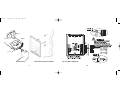
1. Outdoor Remote Sensor
2. Heating (Flame %), Cooling (Snowflake ☛)
3. Days of the week
4. MODE button (Toggles between Heat, Cool, Auto, Off)
5. Temporary Override
6. FAN button (Toggles between Constant or Automatic
Fan)
7. Communication Link established
8. Perimeter Heat LED
9. Room Temperature Display
10. Temperature Setpoint change
11. Events (Morning ✣, Day ✥, Evening ✤, Night ✠)
12. Time of day or Mode of Operation
13. OUTDOOR button (Displays outdoor temperature)
14. Keypad locked
15. ZONE button (Displays zone number of thermostat)
16. Fan
17. ✟ ✞ buttons (Raise or lower setpoint or toggle
between ˚C or ˚F when pressed simultaneously)
1.
2.
3.
4.
5.
Perimeter Heat LED
Date Code & Model Number
DIP Switch
Printed circuit board
Thermistor: measures room temperature
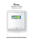
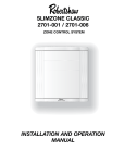
DSL-520P USER INTERFACE, LED AND SWITCHES
4
110-906
9/25/00
10:47 AM
Page 8
COMMUNICATION
24L:
24VAC transformer
The thermostat and the SZP control module are in constant communication with each other at
1200 baud using a RS485 interface. The satellite dish symbol ✬ will appear in the lower lefthand corner of the display when the units are communicating properly. During communication the uplink symbol (✭) will flash randomly. The satellite dish symbol ✬ disappears if the
DSL-520P loses communication with the SZP control module. The thermostat receives the
following operating parameters from the control module:
- temperature setpoint values
- morning, day, evening, and night event schedules
- time of day and outdoor temperature value
24N:
24VAC transformer common
OPTIONAL FEATURES AND EQUIPMENT
The following are some of the options available for your electronic thermostat to further
enhance and expand its capabilities. The following are descriptions only. Refer to the instructions provided with these components for wiring information.
SL-IDS REMOTE INDOOR TEMPERATURE SENSOR
The Robertshaw remote indoor sensor (SL-IDS) is easy to install and provides accurate digital
communication of room temperature to the controlling thermostat from up to 300 feet (90m),
using 3-wire, 18-24 AWG unshielded copper cable wired directly to the thermostat (RS2, RS1,
and RS+V). There are no switches to set. The thermostat detects the remote sensor connection
5
PC:
24N:
PO:
power damper closed
common
power damper opened
Power to the dampers is provided by the 24L and 24N terminals at each zone terminal strip.
Refer to section 3.4 of the SZP manual for information on sizing transformers.
WIRING INFORMATION
Use #18AWG (nonshielded) copper wire for all system wiring; thermostats may use 18-24
AWG wire. Thermostats and damper actuators may be located up to 300 ft. (90m) from the
control module. All system wires should be tagged to identify thermostat, damper and equipment wiring. Refer to section 4.2 of the SZP manual for the control module wiring diagram. It
is strongly recommended that a spare or third wire be run between the control module and each
zone damper in the event that a three (3) wire damper actuator is used or required in the future.
CURRENT LIMITED OUTPUT TERMINALS
All output circuits on the SlimZone Premier control module incorporate self-resetting current
14
110-906
9/25/00
10:47 AM
Page 9
4. Return the temperature setpoint to its original value. Note that selecting the OFF mode
clears the ✧ symbol, ending the temporary override.
and RS+V). There are no switches to set. The thermostat detects the remote sensor connection
and controls temperature based on the data received.
5. Press the FAN button until the fan symbol (') appears; the green LED (fan) will light
up at the SZP control module.
PERIMETER HEAT
6. Press the FAN button again if constant fan is not required.
The W1 and R terminals on the DSL-520P are designated for use with perimeter heat, one for
each zone. The perimeter heat will be activated when the thermostat requests heat and the SZP
control module is not demanding heat from the main heating source.
DAMPERS
Robertshaw dampers are designed to work with low pressure systems (1.0" WC or less).
Balancing dampers should be installed ahead of all zone dampers. Zone dampers should be
installed 10 ft. (3 m) back from discharge grille. A flex or lined duct is recommended for the
last 5 ft. (1.5 m). Enerstat dampers are two (2) position dampers. Two (2) wire dampers are
powered closed and spring return open. Three (3) wire dampers are powered closed and powered open. For applications requiring minimum air ventilation, an adjustment screw is available to set the damper to a specified minimum open position. Enerstat dampers are shipped
from the factory with the minimum position adjustment screw in the fully closed position;
allow for a 3% to 5% leakage with damper closed. The control module has five (5) terminals
at each zone terminal strip for damper connections, which are as follows:
13
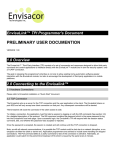
Terminal
Function
R
24VAC input for perimeter heat
W1
Perimeter heat dry contact output
RS2, RS1
RS+V
Indoor remote sensor connections. Refer to the instructions
included with the sensor.
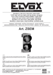
1-4
Communication terminals to the SZP control module. The terminals must be connected 1-1, 2-2, 3-3, 4-4 to function and prevent
damage.
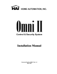
DSL-520P OUTPUT TERMINALS, LED DESIGNATIONS
6
110-906
9/25/00
10:47 AM
Page 10
THERMOSTAT INSTALLATION: DSL-520P
THERMOSTAT VERIFICATION
LOCATION
The thermostat operation may be verified only when the SZP control module is powered; the
control module provides power to the zone thermostats. Verify operation as follows:
The most important consideration in installing your DSL-520P Communicating Zone thermostat is where to locate the unit. The location can radically affect the operation of the thermostat. To ensure proper operation, the thermostat should be mounted on an inside wall in a
frequently occupied area of the zone. In addition, its position must be at least 18 inches (46 cm)
from any outside wall, and approximately 5 feet (1.5 m) above the floor in a location with
freely circulating air of an average temperature.
BE SURE TO AVOID THE FOLLOWING LOCATIONS:
* behind doors or in corners where freely circulating air is unavailable
* where direct sunlight or radiant heat from appliances might affect control operation
* on an outside wall
* adjacent to, or in line with, conditioned air discharge grilles, stairwells, or outside doors
* where its operation may be affected by steam or water pipes or warm air stacks in an
adjacent partition space, or by an area not heated or cooled behind the thermostat
* where its operation will be affected by the supply air of an adjacent unit
* near sources of electrical interference such as arcing relay contacts
7
1. Check that the satellite dish symbol appears at the lower left corner of the display and that
the uplink symbol ✭ flashes occasionally. If the symbols are present, the thermostat and the
SZP control module are communicating properly. If the symbols are not present, the thermostat and the module are not communicating. If ✫ is not present, check communication
wiring and ensure that polarity is correct.
2. Press the MODE button to select either the heat % or cool ☛ mode. The flame and snowflake
symbols start flashing only when SZP finally brings on the equipment.
3. Press the ✟ button to raise the temperature setpoint above (in heat mode), or the ✞ button to
lower the temperature setpoint below (in cool mode), the current displayed temperature.
Within a few seconds, the thermostat should call for either heating or cooling. Check at the
SZP control module that the orange LED (heating) or the yellow LED (cooling) for this
zone’s input is ON, indicating that the control module has acknowledged the call. Note that
the equipment might not be activated depending on the setup and status of the control module.
12
110-906
9/25/00
10:47 AM
Page 11
REASSEMBLING THE THERMOSTAT TO THE INSTALLED BACKPLATE
INSTALLATION
Before the thermostat is reassembled to the backplate, ensure the following:
1. Lift the thermostat access cover and insert a coin or large flat blade screwdriver into the
slot located in the bottom center of the case and twist 1/4 turn (be extremely careful not to
insert more than 1/8" [3 mm] into the casing, as this may damage the circuit board). Grasp
the lower corners of the thermostat body and separate from the thermostat backplate.
Swing the thermostat out from the bottom, and lift up and out of the base.
* Polarity has been respected for the communication wires.
* All wires for peripheral components (SL-IDS, perimeter heat) are connected.
* Ensure all wires are properly inserted and screwed down in terminal blocks.
* Ensure dipswitches are set appropriately
Reassemble the thermostat as follows:
1. Position the housing assembly inside the access panel.
2. Position the housing and access panel assembly on the hinged tabs located at the top of the
installed backplate.
3. Gently swing the thermostat and access cover downwards and press on the bottom center
edge until it snaps into place.
2. Place the rectangular opening on the thermostat backplate over the equipment control wires
protruding from the wall. Using the base as a template, mark the location of the two (2)
mounting holes. No leveling is required.
3. Use the supplied anchors and screws for mounting on the drywall or plaster. Drill two (2)
3/16" (5 mm) holes at the marked locations and tap nylon anchors flush to the wall surface.
Fasten the backplate to the wall.
4. Connect the control module wires to the thermostat terminal blocks. Connect the low voltage wires from the perimeter heat device if installed.
NOTE: TEMPERATURE ACCURACY
Full temperature accuracy will only be realized after the thermostat has been installed and powered for at least one (1) hour.
11
5. Push any extra or slack wire back into the wall. Dress the remaining wires so they are flush
to the mounting plate. The access hole should be sealed or stuffed to prevent drafts from the
wall affecting the thermostat.
8
110-906
9/25/00
10:47 AM
Page 12
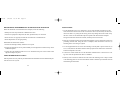
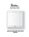
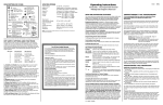
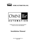
Access Cover
Assembly
Housing
Backplate
ATTACHING BACKPLATE TO THE WALL
SEPARATING THERMOSTAT AND BACKPLATE
9
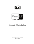
DSL-520P ZONE CONNECTIONS
10
110-906
9/25/00
10:47 AM
Page 12
Access Cover
Assembly
Housing
Backplate
ATTACHING BACKPLATE TO THE WALL
SEPARATING THERMOSTAT AND BACKPLATE
9
DSL-520P ZONE CONNECTIONS
10
110-906
9/25/00
10:47 AM
Page 11
REASSEMBLING THE THERMOSTAT TO THE INSTALLED BACKPLATE
INSTALLATION
Before the thermostat is reassembled to the backplate, ensure the following:
1. Lift the thermostat access cover and insert a coin or large flat blade screwdriver into the
slot located in the bottom center of the case and twist 1/4 turn (be extremely careful not to
insert more than 1/8" [3 mm] into the casing, as this may damage the circuit board). Grasp
the lower corners of the thermostat body and separate from the thermostat backplate.
Swing the thermostat out from the bottom, and lift up and out of the base.
* Polarity has been respected for the communication wires.
* All wires for peripheral components (SL-IDS, perimeter heat) are connected.
* Ensure all wires are properly inserted and screwed down in terminal blocks.
* Ensure dipswitches are set appropriately
Reassemble the thermostat as follows:
1. Position the housing assembly inside the access panel.
2. Position the housing and access panel assembly on the hinged tabs located at the top of the
installed backplate.
3. Gently swing the thermostat and access cover downwards and press on the bottom center
edge until it snaps into place.
2. Place the rectangular opening on the thermostat backplate over the equipment control wires
protruding from the wall. Using the base as a template, mark the location of the two (2)
mounting holes. No leveling is required.
3. Use the supplied anchors and screws for mounting on the drywall or plaster. Drill two (2)
3/16" (5 mm) holes at the marked locations and tap nylon anchors flush to the wall surface.
Fasten the backplate to the wall.
4. Connect the control module wires to the thermostat terminal blocks. Connect the low voltage wires from the perimeter heat device if installed.
NOTE: TEMPERATURE ACCURACY
Full temperature accuracy will only be realized after the thermostat has been installed and powered for at least one (1) hour.
11
5. Push any extra or slack wire back into the wall. Dress the remaining wires so they are flush
to the mounting plate. The access hole should be sealed or stuffed to prevent drafts from the
wall affecting the thermostat.
8
110-906
9/25/00
10:47 AM
Page 10
THERMOSTAT INSTALLATION: DSL-520P
THERMOSTAT VERIFICATION
LOCATION
The thermostat operation may be verified only when the SZP control module is powered; the
control module provides power to the zone thermostats. Verify operation as follows:
The most important consideration in installing your DSL-520P Communicating Zone thermostat is where to locate the unit. The location can radically affect the operation of the thermostat. To ensure proper operation, the thermostat should be mounted on an inside wall in a
frequently occupied area of the zone. In addition, its position must be at least 18 inches (46 cm)
from any outside wall, and approximately 5 feet (1.5 m) above the floor in a location with
freely circulating air of an average temperature.
BE SURE TO AVOID THE FOLLOWING LOCATIONS:
* behind doors or in corners where freely circulating air is unavailable
* where direct sunlight or radiant heat from appliances might affect control operation
* on an outside wall
* adjacent to, or in line with, conditioned air discharge grilles, stairwells, or outside doors
* where its operation may be affected by steam or water pipes or warm air stacks in an
adjacent partition space, or by an area not heated or cooled behind the thermostat
* where its operation will be affected by the supply air of an adjacent unit
* near sources of electrical interference such as arcing relay contacts
7
1. Check that the satellite dish symbol appears at the lower left corner of the display and that
the uplink symbol ✭ flashes occasionally. If the symbols are present, the thermostat and the
SZP control module are communicating properly. If the symbols are not present, the thermostat and the module are not communicating. If ✫ is not present, check communication
wiring and ensure that polarity is correct.
2. Press the MODE button to select either the heat % or cool ☛ mode. The flame and snowflake
symbols start flashing only when SZP finally brings on the equipment.
3. Press the ✟ button to raise the temperature setpoint above (in heat mode), or the ✞ button to
lower the temperature setpoint below (in cool mode), the current displayed temperature.
Within a few seconds, the thermostat should call for either heating or cooling. Check at the
SZP control module that the orange LED (heating) or the yellow LED (cooling) for this
zone’s input is ON, indicating that the control module has acknowledged the call. Note that
the equipment might not be activated depending on the setup and status of the control module.
12
110-906
9/25/00
10:47 AM
Page 9
4. Return the temperature setpoint to its original value. Note that selecting the OFF mode
clears the ✧ symbol, ending the temporary override.
and RS+V). There are no switches to set. The thermostat detects the remote sensor connection
and controls temperature based on the data received.
5. Press the FAN button until the fan symbol (') appears; the green LED (fan) will light
up at the SZP control module.
PERIMETER HEAT
6. Press the FAN button again if constant fan is not required.
The W1 and R terminals on the DSL-520P are designated for use with perimeter heat, one for
each zone. The perimeter heat will be activated when the thermostat requests heat and the SZP
control module is not demanding heat from the main heating source.
DAMPERS
Robertshaw dampers are designed to work with low pressure systems (1.0" WC or less).
Balancing dampers should be installed ahead of all zone dampers. Zone dampers should be
installed 10 ft. (3 m) back from discharge grille. A flex or lined duct is recommended for the
last 5 ft. (1.5 m). Enerstat dampers are two (2) position dampers. Two (2) wire dampers are
powered closed and spring return open. Three (3) wire dampers are powered closed and powered open. For applications requiring minimum air ventilation, an adjustment screw is available to set the damper to a specified minimum open position. Enerstat dampers are shipped
from the factory with the minimum position adjustment screw in the fully closed position;
allow for a 3% to 5% leakage with damper closed. The control module has five (5) terminals
at each zone terminal strip for damper connections, which are as follows:
13
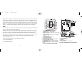
Terminal
Function
R
24VAC input for perimeter heat
W1
Perimeter heat dry contact output
RS2, RS1
RS+V
Indoor remote sensor connections. Refer to the instructions
included with the sensor.
1-4
Communication terminals to the SZP control module. The terminals must be connected 1-1, 2-2, 3-3, 4-4 to function and prevent
damage.
DSL-520P OUTPUT TERMINALS, LED DESIGNATIONS
6
110-906
9/25/00
10:47 AM
Page 8
COMMUNICATION
24L:
24VAC transformer
The thermostat and the SZP control module are in constant communication with each other at
1200 baud using a RS485 interface. The satellite dish symbol ✬ will appear in the lower lefthand corner of the display when the units are communicating properly. During communication the uplink symbol (✭) will flash randomly. The satellite dish symbol ✬ disappears if the
DSL-520P loses communication with the SZP control module. The thermostat receives the
following operating parameters from the control module:
- temperature setpoint values
- morning, day, evening, and night event schedules
- time of day and outdoor temperature value
24N:
24VAC transformer common
OPTIONAL FEATURES AND EQUIPMENT
The following are some of the options available for your electronic thermostat to further
enhance and expand its capabilities. The following are descriptions only. Refer to the instructions provided with these components for wiring information.
SL-IDS REMOTE INDOOR TEMPERATURE SENSOR
The Robertshaw remote indoor sensor (SL-IDS) is easy to install and provides accurate digital
communication of room temperature to the controlling thermostat from up to 300 feet (90m),
using 3-wire, 18-24 AWG unshielded copper cable wired directly to the thermostat (RS2, RS1,
and RS+V). There are no switches to set. The thermostat detects the remote sensor connection
5
PC:
24N:
PO:
power damper closed
common
power damper opened
Power to the dampers is provided by the 24L and 24N terminals at each zone terminal strip.
Refer to section 3.4 of the SZP manual for information on sizing transformers.
WIRING INFORMATION
Use #18AWG (nonshielded) copper wire for all system wiring; thermostats may use 18-24
AWG wire. Thermostats and damper actuators may be located up to 300 ft. (90m) from the
control module. All system wires should be tagged to identify thermostat, damper and equipment wiring. Refer to section 4.2 of the SZP manual for the control module wiring diagram. It
is strongly recommended that a spare or third wire be run between the control module and each
zone damper in the event that a three (3) wire damper actuator is used or required in the future.
CURRENT LIMITED OUTPUT TERMINALS
All output circuits on the SlimZone Premier control module incorporate self-resetting current
14
110-906
9/25/00
10:47 AM
Page 7
limiting devices which provide protection against excessive current draws caused by circumstances such as wiring shorts on an output. These devices, referred to as polyfuses, are activated in general when the current draw exceeds 2.5 Amps. The value and the duration of the
excess current is taken into account. The polyfuses will allow excess currents of very short
duration (i.e., spikes) in order to prevent circuit interruptions by noisy lines or occasional minor
surges. In its current limiting mode, the polyfuses reduce the output current to milliamps.
NOTE:
The low leakage current may be sufficient to produce a small voltage reading when measured
with a volt meter with a high input impedance.
When the cause of the excess current has been removed and the current draw is returned to a
value below 2.5Amps, the polyfuses will reestablish full output current; in some instances this
may take up to twenty (20) seconds. Polyfuses eliminate the need to replace blown fuses.
The SZP control module uses red LEDs to indicate when a problem exists with the current
being drawn from certain circuits. An LED exists for the following on-board circuits:
* each zone damper circuit
* each zone thermostat circuit (current limited at 0.1Amp)
* on the cool terminal strip
* on the heat terminal strip
15
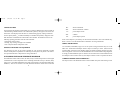
1. Outdoor Remote Sensor
2. Heating (Flame %), Cooling (Snowflake ☛)
3. Days of the week
4. MODE button (Toggles between Heat, Cool, Auto, Off)
5. Temporary Override
6. FAN button (Toggles between Constant or Automatic
Fan)
7. Communication Link established
8. Perimeter Heat LED
9. Room Temperature Display
10. Temperature Setpoint change
11. Events (Morning ✣, Day ✥, Evening ✤, Night ✠)
12. Time of day or Mode of Operation
13. OUTDOOR button (Displays outdoor temperature)
14. Keypad locked
15. ZONE button (Displays zone number of thermostat)
16. Fan
17. ✟ ✞ buttons (Raise or lower setpoint or toggle
between ˚C or ˚F when pressed simultaneously)
1.
2.
3.
4.
5.
Perimeter Heat LED
Date Code & Model Number
DIP Switch
Printed circuit board
Thermistor: measures room temperature
DSL-520P USER INTERFACE, LED AND SWITCHES
4
110-906
9/25/00
10:47 AM
Page 6
The SZP system uses 7 day programmability with 2 or 4 events per day. Programming is done
at the SZP control module only. The DSL-520P thermostat provides the ability to temporarily
deviate from the established program by simply pressing the ✞ or ✟ buttons to change the temperature setpoints. In addition, you may choose to display the temperature in °F or °C.
The thermostat also allows you to select constant fan operation (useful when using an air cleaner) or have the fan activated automatically when the heating or cooling equipment is energized.
FEATURES
* Nonprogrammable (programming is done at the SZP control module)
* Powered by the SZP control module (no separate transformer required)
* User friendly keypad providing access to system parameters such as fan control (FAN),
mode of operation (MODE), outdoor temperature (OUTDOOR) and zone identification
(ZONE)
* Selectable Celsius or Fahrenheit temperature display
* Selectable 12 or 24 hour clock display
* Constant fan or automatic fan operation
* Internal switch to lock-out the keypad to prevent tampering
* No batteries required — always remembers the fan setting and mode of operation (all other
parameters remembered by SZP control module)
* 2°F (1°C) minimum heat/cool separation
* Minimum call time (2 or 4 minute, selectable)
* Dry contact relay output for perimeter heat with LED indicator
* Lockable access cover
3
SETTING YOUR THERMOSTAT
MODE Button
This button allows selection between the four (4) modes available: OFF, COOL ☛,
HEAT %, AUTO ☛ %. The words (accompanied by their appropriate symbols) HEAT,
COOL, and AUTO are displayed for five seconds. The word OFF remains visible.
To set the desired mode of operation, do the following:
1. Press and release MODE button until the word HEAT is momentarily displayed;
the % symbol remains to remind you that the thermostat is in heat mode. The thermostat will activate the heating system only, based on the HEAT temperature setpoint.
2. Press and release MODE button until the word COOL is momentarily displayed;
the ☛ symbol remains to remind you that the thermostat is in cool mode. The thermostat will activate the cooling system only, based on the COOL temperature setpoint.
3. Press and release MODE button until the word AUTO is momentarily displayed;
the ☛% symbols remain to remind you that the thermostat is in auto changeover
mode. The thermostat will activate the heating or cooling equipment, based on the
previously established temperature setpoints for both modes.
4. Press and release MODE button until the word OFF is displayed; OFF remains to
remind you that the thermostat is in off mode. In the off mode, the thermostat displays the room temperature and ignores the temperature setpoints; the thermostat will
not make any calls for equipment.
5. Press and release the MODE button until you have selected the desired mode of
operation.
16
110-906
9/25/00
10:47 AM
Page 5
FAN Button
This button allows selection between constant fan or auto fan mode. The constant fan
mode continuously displays the ' symbol; auto fan mode means that the fan only
activates when heating or cooling equipment has been activated; the ' symbol
does not appear when the fan is activated during a call for cooling or heating.
1. Press and release the FAN button until the desired fan mode has been selected.
2. Constant fan mode is recommended for electronic air cleaners and constant ventilation requirements.
OUTDOOR Button
This button allows the thermostat to display the outdoor temperature, if the SlimZone
Environmental Module (SZEM) has been installed with an optional outdoor remote
temperature sensor. (Refer to section 4.6 for ZSEM module information.)
1. Press OUTDOOR button; the ✜ icon is displayed, along with the outdoor temperature just below. If there is no remote sensor connected the temperature display will
show - -.
2. Release the OUTDOOR button; the thermostat will again display the indoor temperature.
ZONE Button
Pressing the ZONE button displays the zone number where the thermostat is located
and indicates to which input it is connected to on the SZP control module.
17
DSL-520P ZONE THERMOSTAT
INTRODUCTION
The nonprogrammable DSL-520P zone thermostat is the exclusive thermostat used with the
SlimZone Premier (SZP) system. The system will not function with any other thermostat.
The DSL-520P is a fully communicating thermostat which is powered by the SZP control module and is constantly exchanging data with the control module to optimize control of the zoned
environment. It represents the most advanced solid-state, microprocessor temperature control
on the market today.
The thermostat has been designed to provide accurate control and display of room temperature,
and normally displays room temperature, mode of operation and whether cooling or heating is
currently on.
Your new thermostat uses an adaptive control routine, based on Fuzzy logic, to determine the
heating or cooling load of the area in which it is installed. The routine calculates the load by
evaluating recent room conditions (from the sensor within the thermostat or connected remote
sensor) and reactions to heating and cooling. The load factor is then used to determine when
your equipment should be activated and for how long, providing optimum control and economy.
2
110-906
9/25/00
10:47 AM
Page 4
IMPORTANT
READ THIS BOOKLET THOROUGHLY IN ORDER TO
UNDERSTAND ALL THE OPERATION FEATURES OF YOUR
ENVIRONMENTAL MODULE.
Changing the Temperature Setpoints
Change the temperature setpoints by pressing the ✞!or ✟!buttons to lower or raise
the displayed setpoint. Pressing the buttons once will display only the current setpoints that the thermostat is controlling. Press and hold to change the value.
To access a setpoint, the thermostat must be in a mode of operation where the setpoint would be used (e.g., to change the heat setpoint, the thermostat must be in
either the heat or auto mode). The mode symbol for the setpoint being displayed (%
for heat and ☛ for cool) will also appear. When in the auto mode, the thermostat will
first display either of the two setpoints, heat or cool. To view or change the opposite
setpoint, press the MODE button.
RECORD THE SERIAL NUMBER IN THE SPACE
PROVIDED.
°C or °F
SERIAL NUMBER
Press the ✞! and ✟! buttons simultaneously to change the displayed temperature
from Celsius (°C ) to Fahrenheit (°F), and vice versa.
DATE OF INSTALLATION
12 or 24 Hour Clock
Press and hold the FAN button, then press the OUTDOOR button to change the time
of day display to 12 or 24 hour format.
1
18
110-906
9/25/00
10:47 AM
Page 3
Local Temporary Override
TABLE OF CONTENTS
OCCUPIED PERIOD
When in either the morning, day or evening program, the temperature setpoints
may be changed at the zone thermostats by simply pressing the ✞ or ✟ buttons.
The selected setpoints remain valid for the duration of the occupied period. When
the unit changes over to the unoccupied period, the override setpoints are discarded
and the thermostat reverts to the setpoints established by the SZP control module
for the night program.
UNOCCUPIED PERIOD
System: Unoccupied mode occurs when all zone thermostats are in night mode.
Local: Unoccupied mode occurs when a zone thermostat goes into night mode.
The minimum temporary override is one (1) hour and will remain in effect until the
one (1) hour period has elapsed. Moving into an unoccupied period (night mode)
during this minimum temporary override will not affect its status.
During the unoccupied period, zones 1-13 act as MUST SERVICE zones when the
zone thermostat ✞ or ✟ buttons (system override) are depressed. Zones 14-19 do not
act as MUST SERVICE zones at this time.
Keypad Lockout
With the keypad locked out (DIP switch #2 in the ON position) the MODE, FAN,
and ✞ and ✟ buttons are disabled; the lock symbol $ appears when these buttons are
pressed. The OUTDOOR and ZONE buttons still function.
19
12- or 24-Hour Clock . . . . . . . . . . . . . . . . . . . . . . . . . . . . . . . . . . . . . . . . . . . . . . . . . . . . 18
Local Temporary Override . . . . . . . . . . . . . . . . . . . . . . . . . . . . . . . . . . . . . . . . . . . . . . . . 19
Keypad Lockout . . . . . . . . . . . . . . . . . . . . . . . . . . . . . . . . . . . . . . . . . . . . . . . . . . . . . . . . 19
Warranty . . . . . . . . . . . . . . . . . . . . . . . . . . . . . . . . . . . . . . . . . . . . . . . . . . . . . . . . . . . . 20
110-906
9/25/00
10:47 AM
Page 2
TABLE OF CONTENTS
IMPORTANT . . . . . . . . . . . . . . . . . . . . . . . . . . . . . . . . . . . . . . . . . . . . . . . . . . . . . . . . . .1
INTRODUCTION . . . . . . . . . . . . . . . . . . . . . . . . . . . . . . . . . . . . . . . . . . . . . . . . . . . . . . .2
Features . . . . . . . . . . . . . . . . . . . . . . . . . . . . . . . . . . . . . . . . . . . . . . . . . . . . . . . . . . . . . . .3
Communication . . . . . . . . . . . . . . . . . . . . . . . . . . . . . . . . . . . . . . . . . . . . . . . . . . . . . . . . . .5
Optional Features and Equipment . . . . . . . . . . . . . . . . . . . . . . . . . . . . . . . . . . . . . . . . . . . . 5
SL-IDS Remote Indoor Temperature Sensor . . . . . . . . . . . . . . . . . . . . . . . . . . . . . . . . . . . . 5
Perimeter Heat . . . . . . . . . . . . . . . . . . . . . . . . . . . . . . . . . . . . . . . . . . . . . . . . . . . . . . . . . . 6
THERMOSTAT INSTALLATION . . . . . . . . . . . . . . . . . . . . . . . . . . . . . . . . . . . . . . . . . . 7
Location . . . . . . . . . . . . . . . . . . . . . . . . . . . . . . . . . . . . . . . . . . . . . . . . . . . . . . . . . . . . . . . 7
Installation . . . . . . . . . . . . . . . . . . . . . . . . . . . . . . . . . . . . . . . . . . . . . . . . . . . . . . . . . . . . . 8
Reassembling the Thermostat to the Installed Backplate . . . . . . . . . . . . . . . . . . . . . . . . . . 11
Temperature Accuracy. . . . . . . . . . . . . . . . . . . . . . . . . . . . . . . . . . . . . . . . . . . . . . . . . . . . 11
Thermostat Verification . . . . . . . . . . . . . . . . . . . . . . . . . . . . . . . . . . . . . . . . . . . . . . . . . . . 12
Dampers . . . . . . . . . . . . . . . . . . . . . . . . . . . . . . . . . . . . . . . . . . . . . . . . . . . . . . . . . . . . . . 13
Wiring Information . . . . . . . . . . . . . . . . . . . . . . . . . . . . . . . . . . . . . . . . . . . . . . . . . . . . . . 14
Current Limited Output Terminals. . . . . . . . . . . . . . . . . . . . . . . . . . . . . . . . . . . . . . . . . . . 14
SETTING YOUR THERMOSTAT . . . . . . . . . . . . . . . . . . . . . . . . . . . . . . . . . . . . . . . . . 16
MODE Button. . . . . . . . . . . . . . . . . . . . . . . . . . . . . . . . . . . . . . . . . . . . . . . . . . . . . . . . . . 16
FAN Button. . . . . . . . . . . . . . . . . . . . . . . . . . . . . . . . . . . . . . . . . . . . . . . . . . . . . . . . . . . . 17
OUTDOOR Button . . . . . . . . . . . . . . . . . . . . . . . . . . . . . . . . . . . . . . . . . . . . . . . . . . . . . . 17
ZONE Button . . . . . . . . . . . . . . . . . . . . . . . . . . . . . . . . . . . . . . . . . . . . . . . . . . . . . . . . . . 17
Changing the Temperaure Setpoints . . . . . . . . . . . . . . . . . . . . . . . . . . . . . . . . . . . . . . . . . 18
°C or °F . . . . . . . . . . . . . . . . . . . . . . . . . . . . . . . . . . . . . . . . . . . . . . . . . . . . . . . . . . . . . . 18
WARRANTY
LIMITED TWO YEAR WARRANTY
The manufacturer warrants to the original purchaser that its product and component
parts will be free from defects in workmanship and materials for a period of two
years from the date of purchase. Your dealer will provide free replacement of your
thermostat upon proof of purchase.
EXCLUSIONS
This warranty does not apply in the event of misuse, abuse, or as a result of unauthorized alterations or repairs. The manufacturer will not be liable for any consequential damages including, without limitation, damages resulting from defects, loss
of use or misuse.
This equipment, if installed in strict accordance with the manufacturer’s instructions,
complies with the limits for a class B computing device pursuant to Subpart J of Part
15 of FCC rules.
20
110-906
9/25/00
10:47 AM
Page 1
Installation
&
Operating Instructions
for
110-906
97302
DSL-520P
COMMUNICATING ZONE
THERMOSTAT