1
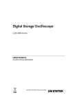
READ THIS
BOOK FIRST
Instruction Manual
The
Epic
By Holland
BH421-AG4
L.P. Tank
not included.
L.P. NOTICE: This grill shall
be connected only to a 20 lb.
L.P. cylinder that is equipped
with a Sherwood Valve
#PV3349 AND an overfill
protection device (OPD).
The only Grill
TM
BARBECUE INDUSTRY
ASSOCIATION MEMBER
TM
not to flare up!
©The Holland Grill Co., Inc. V2007 PN SG5-002
ANSI Z21.58b-2006/CSA 1.6b-2006
!
DANGER
IF YOU SMELL GAS:
1. SHUT OFF GAS TO APPLIANCE.
2. EXTINGUISH ANY OPEN FLAME.
3. OPEN LID.
4. IF ODOR CONTINUES, KEEP AWAY FROM
THE APPLIANCE AND IMMEDIATELY CALL
YOUR GAS SUPPLIER OR YOUR FIRE
DEPARTMENT.
!
WARNING
1. DO NOT STORE OR USE GASOLINE OR
OTHER FLAMMABLE LIQUIDS OR VAPORS IN
THE VICINITY OF THIS OR ANY OTHER
APPLIANCE.
2. AN LP CYLINDER NOT CONNECTED FOR
USE SHALL NOT BE STORED IN THE VICINITY
OF THIS OR ANY OTHER APPLIANCE.
Cutaway Side View
of your patented Holland Grill
No Flare-up System
Vent Stacks
They provide just the right amount of ventilation
to circulate the heat. Your foods cook evenly
on all sides.
Stainless Steel
Cooking Grid
Stainless steel grid cleans
easily and prevents small
foods from falling through.
Aluminim
Drip Pan
Catches all the drippings
and prevents them from
catching fire.
Flame Deflector
Stainless Steel shield
distrubutes the heat evenly.
Cast Iron Burner
Guaranteed for life!
Simply close the lid and cook by time.
It’s guaranteed not to flare-up.
Thank you for purchasing a Holland Grill. This is truly a grill that you, your family and friends
will use and enjoy for many years to come.
Many years of research and new technology have gone into the entire line of Holland grills,
ensuring they are safe, easy to use and grill to perfection. It’s important that you are aware
that the Holland Grill is unlike any other grill on the market today. By design, it
allows you to grill, steam or smoke without the worry of flare-ups associated with competitive
brands. Now you can relax while preparing food without the worry and nuisance of trying to
control flames that will ruin your food.
Not only will you be able to enjoy time with friends and family while you grill worry-free, you’ll
be able to do so for years to come. All Holland grills are made of top quality materials which
give them a sturdiness that will last for years. We use only the best materials to ensure your
new grill will look like new and cook like new well into the future. This grill was designed and
made for trouble-free outdoor cooking.
Please read and follow all the instructions in this manual.
HOLLAND EPIC GRILL OWNERS MANUAL
Safety Information
The Fuel System
Please read carefully.
FOR YOUR SAFETY
• IF YOU SMELL GAS:
1. SHUT OFF GAS TO THE APPLIANCE.
2. EXTINGUISH ANY OPEN FLAME.
3. OPEN LID.
4. IF ODOR CONTINUES, IMMEDIATELY CALL YOUR GAS SUPPLIER
OR FIRE DEPARTMENT.
FOR YOUR SAFETY
1. DO NOT STORE OR USE GASOLINE OR OTHER FLAMMABLE VAPORS
AND LIQUIDS IN THE VICINITY OF THIS OR ANY OTHER APPLIANCE.
2. AN LP CYLINDER NOT CONNECTED FOR USE SHALL NOT BE
STORED IN THE VICINITY OF THIS OR ANY OTHER APPLIANCE.
(A) DO NOT STORE A SPARE LP-GAS CYLINDER UNDER OR NEAR
THIS APPLIANCE;
(B) NEVER FILL THE CYLINDER BEYOND 80 PERCENT FULL; AND
(C) IF THE INFORMATION IN “(A)” AND “(B)” IS NOT
FOLLOWED EXACTLY, A FIRE CAUSING DEATH OR SERIOUS
INJURY MAY OCCUR.
• THIS GRILL IS NOT INTENDED TO BE INSTALLED IN OR ON RECREATIONAL
VEHICLES AND/OR BOATS.
• KEEP OUTDOOR COOKING GAS APPLIANCE AREA CLEAR AND FREE FROM
COMBUSTIBLE MATERIALS, GASOLINE AND OTHER FLAMMABLE VAPORS
AND LIQUIDS
• THIS GRILL SHALL ONLY BE CONNECTED TO AN LP CYLINDER WITH AN OVERFILL
PROTECTION DEVICE (OPD).
• THE GRILL SHOULD BE LIT AND ALLOWED TO OPERATE FOR AT LEAST 30
MINUTES BEFORE USING FOR THE FIRST TIME TO ALLOW PRESERVATIVE TO
BURN OFF. AFTER SMOKE STOPS COMING OUT OF STACKS, GRILL IS READY
FOR YOUR USE AND ENJOYMENT.
• THIS GRILL IS NOT FOR COMMERCIAL USE
• THIS COOKING APPLIANCE IS FOR OUTDOOR USE ONLY AND SHALL NOT BE USED
IN A BUILDING, GARAGE OR ANY OTHER ENCLOSED AREA.
• EXCESSIVELY WINDY OR COLD CONDITIONS MAY AFFECT GRILL COOKING
PERFORMANCE.
• CHOOSE ONLY A LEVEL LOCATION FOR GRILL OPERATION. THE HOLLAND GRILL
MUST BE SITTING SECURELY ON A LEVEL SURFACE FOR PROPER OPERATION
AND EVEN HEAT DISTRIBUTION.
• YOUR GRILL IS MADE FOR OUTDOOR USE ONLY
• THE VENT STACKS AND THE AIR INTAKE OPENINGS SHOULD NEVER BE
BLOCKED OR CLOSED DURING GRILL OPERATION.
• MINIMUM CLEARANCE FROM SIDES AND BACK TO COMBUSTIBLE
CONSTRUCTION, 18 INCHES (50CM) FROM SIDES AND 18 INCHES (50CM) FROM
BACK. IT IS VERY IMPORTANT TO OBSERVE AND MAINTAIN THE PROPER
CLEARANCES FROM COMBUSTIBLE CONSTRUCTION.
• DO NOT USE THIS OUTDOOR APPLIANCE UNDER OVERHEAD COMBUSTIBLE
SURFACES.
• DO NOT STORE A SPARE LP GAS CYLINDER UNDER OR NEAR THIS APPLIANCE.
WARNING: FOLLOW LOCAL CODES
• THE INSTALLATION OF THIS APPLIANCE MUST CONFORM WITH EITHER
THE NATIONAL FUEL GAS CODE ANSI STANDARD REFERENCED WITH
THE FOLLOWING: ANSI Z223.1/ NFPA 54, NATURAL GAS AND PROPANE
INSTALLATION CODE; CSA B149.1, OR PROPANE STORAGE AND
HANDLING CODE, B149.2, OR THE STANDARD FOR RECREATIONAL
VEHICLES, ANSI A 119.2/NFPA 1192, AND CSA Z240 RV SERIES,
RECREATIONAL VEHICLE CODE, AS APPLICABLE”.
• INSTALLATION SHALL BE IN ACCORDANCE WITH CAN/CGAB149.1
NATURAL GAS AND PROPANE INSTALLATION CODE AND LOCAL
CODES WHERE APPLICABLE.
E-1
Gas grills are used SAFELY by millions of people when following simple SAFETY precautions.
The items in the fuel system are designed for operation with the
Holland Grill. They must not be replaced with any other brand.
(See parts list for replacement items.)
GAS BURNER: The gas burner is constructed of heavy cast iron and
should not require maintenance other than inspection for insect nests
inside the venturi. If you remove the burner for
cleaning, it must be reinstalled exactly as removed.
AIR SHUTTER: See item 11 in lighting instructions (see figure 6 for
details.)
BURNER VALVE: The burner valve is operated in only two
positions. The Off position is when the handle is across (perpendicular
to) the burner, which stops the flow of gas. When the valve has been
set in the Off position, it is important to close the valve at the LP gas
cylinder. The LP gas cylinder is the primary valve and must be closed
when the grill is not in use. The On position is when the handle is in
line with the burner (see figure 6 for details. See lighting instructions
for more information.) The burner valve controls the heat allowed in
the grill by means of a plug orifice. This device is set at the factory
and must not be tampered with or replaced. Turn off LP supply at
cylinder when appliance is not in use.
ONLY A FACTORY SUPPLIED VALVE SHOULD BE USED. (See the
parts list for replacement items.)
LP GAS HOSE: The LP gas hose is designed for use with LP gas
only. Use with any other gas is dangerous. The hose is made of a flexible material to make it easy to install. This material is subject to considerable twisting and turning during installation. It is very important
that the hose be inspected for cracks, cuts, abrasions, wear and loose
fittings before each use of the outdoor cooking gas appliance. The
visual inspection should include leak testing the entire length of hose
and fittings. (See final assembly instructions for more information.)
If the hose shows signs of damage or leakage, it must be replaced
prior to the operation of the grill. Only a factory authorized replacement part can be used. (See the parts list for replacement items.)
Failure to properly inspect or replace hose with an authorized replacement may result in accident or injury.
LP GAS REGULATOR: CAUTION: Use only the gas pressure regulator and hose supplied with this appliance. This regulator and hose is
set for an outlet pressure of 11 inches water column. Substitution of
regulator and hose by any other device or any other manufacturer's
regulator and hose is dangerous and could result in serious injury.
(See the parts list for replacement items.)
IMPORTANT LP CYLINDER INFORMATION: Failure to follow these
DANGER statements exactly may result in a fire causing death or
serious injury.
The Holland Co. Inc. recommends the use of cylinder manufacturers
Manchester and Worthington, Wolfdale with a 47.6 lb water capacity.
Other cylinders may be acceptable for use with the appliance
GRILL INSTALLER - LEAVE THIS INSTRUCTION BOOKLET FOR THE GRILL OWNER.
GRILL OWNER - SAVE THIS INSTRUCTION BOOKLET FOR FUTURE REFERENCE.
provided they are compatible with the appliance retention means (see
figure 9 on page E6 for retention means point of contact).
PROPANE FUEL: Warning – propane is a flammable gas. Improper handling may result in an explosion and/or fire and serious accident or injury.
Your grill is designed to operate on Propane (LP) gas ONLY and is
equipped with the proper orifice for this gas. Caution: Do not connect this
grill to any gas supply except propane or natural gas. Propane gas is
heavier than air and will settle in low areas. Make certain adequate ventilation is available when using your grill and that the gas cylinder is stored
outside in a well ventilated area out of the reach of children when the grill
is not in use.
LP GAS CYLINDER: This grill is designed and intended to be used with
an LP gas cylinder with a nominal LP gas capacity of 20 pounds. Such a
cylinder is approximately 12-3/8" in diameter with an overall height of 181/16". The Holland Grill does not come with an LP gas cylinder. This
must be purchased separately and is available at most hardware stores.
The cylinder used must be constructed and marked in accordance with
the specifications for LP gas cylinders of the U.S. Department of
Transportation (DOT) (4BA-240) and the National Standard of Canada
CAN/CSA-B339, Cylinders, Spheres, and Tubes for the transportation of
dangerous goods. Only a cylinder equipped with an overfill protection
device (OPD) should be used.
The LP gas cylinder shall be used only outdoors in a well ventilated
space and not in a building, garage, or any other enclosed area. The LP
gas cylinder is designed to be used, stored, and transported in the
upright position. The Holland Grill may be stored indoors if the LP gas
cylinder is removed and stored outdoors. NEVER turn the cylinder
upside down or on its side. Always transport, store and use your cylinder
in the upright position. Cylinders must be stored outdoors out of the
reach of children and must not be stored in a building, garage or any
other enclosed area.
The cylinder must be provided with a Sherwood valve, part #PV3349,
which will connect with (quick connect) the QCC-1 Fitting provided on
each of our LP (propane) grills. Must also have a safety relief device having a direct communication with the vapor space of the cylinder. The
cylinder supply system must be mounted vertically for proper vapor withdrawal. The cylinder shall include a collar to protect the cylinder valve.
The grill must be connected to the gas supply by a hose. Turn off LP
supply at cylinder when appliance is not in use.
DO NOT transport a full or empty gas cylinder in a closed automobile
trunk or in a closed passenger area.
Filling the gas cylinder requires removing it from the grill. The cylinder is
attached to the grill by connecting the regulator assembly to the outlet
portion of the gas cylinder valve. This connection is made by the QCC-1
fitting pictured in Figure 1. The large plastic nut fits on the outside of the
threads and turns right, or clockwise to tighten. No tools are necessary.
Hand tight is sufficient. If a good connection is not achieved, the safety
valve inside will not permit the proper amount of gas to flow. When connecting the regulator to the cylinder valve, be sure the pressure relief
valve is directed away from the front and away from the grill. If the relief
valve should open, the propane will be directed where it is likely to do the
least harm. To disconnect regulator assembly turn large plastic nut left or
counter-clockwise.
When disconnecting and connecting the gas cylinder, be careful
that the regulator assembly does not strike the grill, the ground, or
any other surface. If any difficulty at all is had in connecting or disconnecting the regulator assembly to the cylinder valve, contact
your local gas supplier for assistance.
When disconnected from the cylinder, a valve cap must be installed.
(See figure 1.) Place dust cap on cylinder valve outlet whenever the
cylinder is not in use. Only install the type of dust cap on the cylinder valve outlet that is provided with the cylinder valve. Other types
of caps or plugs may result in leakage of propane. Failure to install a
valve cap when the cylinder is disconnected from the fuel system is
dangerous and may result in accident or injury.
When re-connecting the LP gas cylinder, be sure to tighten the fitting until snug. This connection, as well as all other fittings and connections between the cylinder and burner valve, should be inspected for damage and leak tested after every filling or
re-connection.
Keep any electrical supply cord and fuel supply hose away from any
heated surface.
NATURAL GAS: If natural gas is used, contact your local supplier
to set it up properly. The N.G. Holland Grill is set to operate at 7
inches water column pressure, using an orifice with a #48 drill size.
If your grill seems too hot, first call your local gas company to determine what pressure you have.
Never allow anyone to change orifice size without
authorization from factory.
SPARK IGNITER: This grill is equipped with a rotary Piezo igniter
system. A simple Clockwise rotation of the igniter knob produces a
spark at the burner head, lighting the burner. To check that the
spark igniter is working properly, leave gas supply turned OFF and
observe the spark by looking through the peep hole above the control panel or from below the control panel to the left side of the burner in the burner opening. A small blue spark should be visible at the
left side of the burner head every time the igniter “fires”. A loud
“hammer” like sound is produced by the mechanism when sparking.
HANDWHEEL
FIGURE 1
CYLINDER
VALVE
COUPLING
NUT
CONNECT
Clockwise
DISCONNECT,
Counter Clockwise
CAP &
STRAP
REGULATOR
20 LBS
LP GAS CYLINDER
E-2
FIGURE 2b
Cabinet side, RIGHT
FIGURE 3
Cabinet side, LEFT
FIGURE 2a
Cabinet side, RIGHT
8-32 x 3/8 Screw
Insert and fasten Bucket
Bracket into slot as shown
Magnetic Catch
8-32 x 3/8 Hex Nut and Lock Washer
10-24 Phillips head screw
and lock washer
Loosen these 2 bolts.
DO NOT REMOVE COMPLETELY
1/4 - 20 Hex Bolt and
Lock Washer
(typ 8 plcs)
Electrode
Lower Valance
Tank Support
8-32 Phillips head screw
and lock washer
Tank Notches
1/4 - 20 Hex Bolt and
Lock Washer
(typ 4 plcs)
Lower Valance
3/8” Flat Washer
Heavy Duty Caster
ASSEMBLY INSTRUCTIONS
Step 1.
Fasteners Guide
❍
#8-32 x 3/8” Round Head Phillips
#8-32 Lock Washer
#8-32 Hex Nut
On a flat surface (table or carport floor), OPEN AND EMPTY BOTH
BOXES. REFER TO THE CONTENTS LIST TO BE SURE NO PARTS
ARE MISSING. Tighten all factory installed fasteners that may have
loosened during shipping.
Step 2.
#10-24 x 3/8”, #10-24 x 1/2” Round Head Phillips
#10-24x1” Carriage Bolt
1/4 - 20 x 5/8” , 1/4 - 20 x 1” Hex Head Bolt
1/4 - 20 x 1” Round Head Phillips
#10 Lock washer
#10-24x1/2” Carriage Bolt
1/4” Lock washer
#10-24 Hex Nut
#10-24 “Top Lock” Hex Nut
1/4” Hex nut
❍
Attach magnetic catch to right cabinet side panel as shown in Figure
2a using 2 each 8-32 x 3/8 Phillips screws, nuts and lock washers.
❍
Bolt the lower valance (2 ea) to the bottom front/rear of the cabinet side
panels using the 1/4-20 x 5/8” hex head bolts and lock washers as
shown in Figure 2b. Do not fully tighten them at this time.
❍
Select the tank supports. Place the tank supports inside the cabinet
and attach them to the backside of the lower valance as shown in
Figure 2B. NOTE: They will attach toward the left side of the cabinet. Be
sure the notches in the tank support bracket are up. Secure with 1/4-20
x 5/8” hex head bolts and lock washers. Check to make sure that the
cabinet is square by measuring diagonally, before tightening any bolts.
NOTE: Cabinet must be held square in order for the door to open and
close properly. Tighten tank support bolts completely. Now go back and
tighten lower valance bolts completely.
❍
Place one each 3/8” flat washer onto the caster stud. Now screw caster
into the lower valance corners. Tighten securely. Repeat for other 3
corners. NOTE: Locking casters go on the front. Lock the casters to
prevent cabinet from moving around during assembly.
1/4-20 x 1/2” Wing Bolt
(For Tank Hold Down Bracket)
Note: Use one lock washer per bolt, either under the hex nut or under
the bolt head if a hex nut is not used.
E-3
Refer to Figure 2. Select the following parts for assembly:
1. cabinet side panels (2 ea)
4. tank support brackets (2 ea)
2. lower valance (2 ea)
5. magnetic door catch (1ea)
3. casters (4 ea)
FIGURE 4a
Bottom Assembly
1/4 - 20 Hex Bolt
1/4 Lock Washer
(both sides)
FIGURE 4b
Door Pivot Bracket
Route electrode wire
through obround hole
1/4 - 20 Hex Nut
1/4 Lock Washer
(both sides)
10 - 24 x 3/8
Phillips Screw
and Lock Washer
Upper Door
pivot bracket
mounting
location
Secure right
side first
1/4 - 20 x 1/2
Hex Bolt and
Lock Washer
(both sides)
1/4 - 20 x 5/8” Hex bolt
(both sides)
Knob
Washer / Spacers
Door Assembly
Cabinet Assembly
❍
❍
Step 3.
❍
Refer to Figure 3. Select the following items:
1. grill bottom assembly
2. bucket bracket
3. electrode
Now bolt upper rear flange of cabinet sides to rear of grill bottom
assembly as shown. Use 1/4-20 x 1/2 hex head bolts and lock washers. Tighten completely. Repeat for opposite side.
❍
Figure 4b Using a Phillips screwdriver, remove the control panel.
❍
Attach door knob to door panel using 10-24 x 3/8 Phillips screw and
lock washer as shown.
❍
Select the door pivot bracket, washer/spacers and door panel assembly. Slide 2 washer/spacers onto the lower pivot pin of the door assembly. Now insert lower pivot pin with the washer/spacers on it into the
hole in the top surface of the lower valance. Make sure the
washer/spacers do not fall off the pin. Place the door pivot bracket onto
the upper door pivot pin. Now bolt the door pivot bracket to the control
panel bracket as shown using 1/4-20 x 5/8 hex head bolt and lock
washers.
❍
Fasten opposite side of control panel to cabinet side using 1/4-20 x 5/8
hex head bolt and lock washers. Tighten both sides securely.
❍
Re-attach the control panel and plug electrode wire into rotary igniter.
With the grill bottom assembly sitting upright on one end, locate the 1/4
inch diameter hole and slot close to the drain pipe hole. Insert the bucket hanger bracket in the slot as shown in Figure 3 and secure with 1024 x 1/2 Phillips head screw and lock washer. Tighten completely.
Now insert electrode into hole and secure tightly with 8-32 screw and
lock washer. Next, loosen the two 1/4-20 hex bolts shown to prepare for
the next step. DO NOT REMOVE THEM!
Step 4.
Refer to Figure 4a and Figure 4b. Select the following items:
1. grill bottom assembly
5. door pivot bracket
2. cabinet assembly
6. door knob
3. tank heat shield
7. washer/spacer (2)
4. door assembly
❍
❍
Cabinet Assembly
Figure 4a Place the grill bottom assembly onto the cabinet base
assembly. Secure the right side only at this time with 1/4-20 x 5/8 hex
head bolts and, lock washers as shown. Do not tighten at this time.
Select the tank heat shield and slide it under the two bolts that you
loosened in the previous step. Be sure the obround cutout aligns with
the electrode and route the electrode wire through it. Lift the other end
of the tank heat shield up to the flange under the grill body as shown.
Now fasten both sides securely with 1/4-20 x 5/8 hex head bolts and
lock washers.
Step 5.
Refer to Figure 5a and Figure 5b. Select the following items:
1. grill lid assembly
2. hinges
3. lid stops (2)
❍
Figure 5a Select one of the lid stops. Insert the end of the lid stop
with the slot in it into the slot in the body bottom end panel. Insert a 1024 x 1/2 carriage bolt into the square hole in the bottom end panel.
Make sure the bolt goes inside the slot of lid stop. Secure with flat
E-4
FIGURE 5a
10 - 24 Carriage Bolt
bolt must be inserted
in slot of Lid Stop
Shelf
Lid Stop
1/4 - 20 x 5/8
Hex Bolt and
Lock Washer
1/4 - 20 Hex Bolt
and Lock Washer
Hinge
Flat Washer and “Top Lock” Nut
1/4 - 20 x 1 Round head Phillips
Screw and Lock Washer
FIGURE 5b
10 - 24 x 1/2
Carriage Bolt
10 -24 x 1/2 Carriage Bolt
10 - 24 Top Lock Nut
and flat Washer
10 -24
Hex Nut
and Lock
Washer
FIGURE 7
Thermometer
Hole
cutaways for
clarity only
Insert Lid Stop
into slot in Lid
10 -24
Hex Nut
and Lock
Washer
Lid Stop
10 -24 x 1/2 Phillips
Head Screw (8 plcs)
washer and “Top Lock” nut. Tighten the lock nut completely and then
loosen it just enough to allow movement of the lid stop on the screw.
Note: the “Top Lock” nut will be very tight on the screw when installing.
This is normal. Repeat for the opposite side.
❍
Position the shelf onto the brackets as shown. Using 10-24 x 1 carriage
bolts, lock washers and nuts, fasten securely to brackets. Repeat for
opposite side.
Step 7.
❍
Bolt the 2 hinges to the grill bottom assembly using the 1/4-20 x 5/8
hex head bolts and lock washers. Do not fully tighten the hinges at this
time.
❍
Figure 5b Place the lid onto grill bottom assembly. Fasten the body
hinges to the lid assembly using 1/4-20 x 5/8 hex head bolts and lock
washers. Tighten all 8 hinge bolts completely.
❍
Insert a 10-24 x 1/2 carriage bolt into the square hole in the lid end
panel. Then while holding the carriage bolt in place, open the lid just
enough to insert the lid stop through the slot in the lid end panel. Place
the single hole in the lid stop over the carriage bolt. Secure with flat
washer and “Top Lock” nut. Repeat for the opposite side. Note: the “Top
Lock” nut will be very tight on the screw when installing. This is normal.
Tighten the lock nut completely and then loosen it just enough to allow
movement of the lid stop on the screw. Repeat for the opposite side.
Refer to Figure 7. Select the following items:
1. smoke stacks
2. handle and brackets
3. thermometer
❍
Open the lid fully. Using the 10-24 x 1/2 round head Phillips screws,
lock washers and hex nuts fasten the smoke stacks to the grill lid as
shown. Tighten securely.
❍
Install the thermometer through the small hole in the center of the lid
near the smoke stacks. Using a 1/2” wrench, VERY GENTLY, snug
thermometer securing nut. VERY IMPORTANT: DO NOT OVERTIGHTEN.
❍
Select the two handle brackets and handle. First attach the brackets to
the lid using 10-24 X 1/2 carriage bolts, lock washers and hex nuts. DO
NOT FULLY TIGHTEN AT THIS TIME.
Refer to Figure 6. Select the following items:
1. shelf brackets (2 lt. 2 rt.)
2. shelves (2 ea.)
❍
Now place tube handle between handle brackets and secure with 1/420 X 1” round head Phillips screw and lock washer as shown. Tighten
completely.
Select one of the shelf brackets and bolt it to the grill bottom end
panel using 1/4-20 x 5/8 hex head bolts and lock washers. Tighten
completely. Repeat for each of the 3 remaining brackets.
❍
Now go back and tighten completely the handle brackets to lid
Step 6.
❍
E-5
FIGURE 6
10 -24 x 1” Carriage bolt
Cooking g Grid
Drip Pan
FIGURE 8
Drain Pipe
10 -24 Hex Nut
and Lock Washer
Shelf Bracket
Drain Valve
Screws onto drain pipe
Hand tighten only
Utensil Hook
Drip Bucket
Hangs on Bucket
Bracket
Cutaway to
show inside
detail only
Condiment Tray
Step 8.
Refer to Figure 8. Select the following items:
1. drip pan
4. cooking grid
2. drain pipe
5. drip bucket
3. drain valve
❍
Install the drain pipe into the female threaded coupling in the right end
of the drip pan. Tighten with pliers or pipe wrench.
❍
Carefully set the drip pan into grill bottom using the lift tabs at each
end. Line up the drain pipe with the hole in the grill bottom making sure
pipe extends out bottom and drip pan is setting level in its brackets.
❍
❍
Tank Installation
❍
Place your 20-lb. propane tank
into the cabinet base. Make sure
that it is setting securely in the
notches on the tank support
brackets.
❍
Connect the regulator and hose
assembly to the propane tank
valve. This connection is made by
the QCC-1 fitting. The large black
plastic nut fits over the outside of
the tank valve threads and turns
right or clockwise to tighten. No
tools are needed. Hand tight is
sufficient.
Install the brass drain valve onto the drain pipe. Hand tight only is sufficient. DO NOT TIGHTEN WITH WRENCH OR PLIERS! (During the
course of maintenance of the grill you will need to remove the drain
valve.)
Now place your cooking grid into the grill.
❍
❍
Open cabinet door and insert utensil hook in upper hole of door liner
and rotate downward to allow peg on back side of hook to engage
lower hole. Repeat for other 2 hooks.
1/4 - 20
Wing Bolt
FIGURE 9
Be sure that
LP tank sets
in notches in
tank supports
If a good connection is not
achieved, the safety valve inside
will not permit the proper amount
of gas to flow.
Step 9.
Refer to Figure 8. Select the following items:
1. condiment tray
2. utensil hooks (3 ea)
Tank Hold
down Bracket
❍
Next attach and adjust downward
the Tank- Hold-Down bracket (see
Figure 9) to secure the tank. Secure with 1/4-20 x 1/2 wing bolt.
Rear View
Check all bolts and nuts for tightness and then proceed
to leak testing.
Then insert tab hooks on condiment tray into slots in door liner. Allow to
drop down to lock into position.
E-6
LIGHTING INSTRUCTIONS
SOAPY WATER TEST
In a small bowl mix half liquid detergent and half water. Turn on
propane tank valve. Using a small brush, soap all connections
from tank to grill and look for bubbles. Correct all leaks before
proceeding. Turn off propane tank valve.
NOTE: The Holland Grill uses a 2-position gas valve on the
burner control. The left picture under Figure 6 shows the handle in the OFF position. To turn ON push the handle down and
rotate it counter-clockwise to its full travel (about 90 degrees).
See right picture under Figure 6. NEVER operate the Holland
Grill with the handle in any intermediate position.
FOR NATURAL GAS SUPPLY
The Holland Grill, including the gas off-on valve, must be disconnected from the gas supply during any pressure testing of
that system, at test pressures in excess of 1/2 psig.
The Holland Grill must be isolated from the gas supply piping
system by closing the individual manual shut-off valve during
any pressure testing of the gas supply piping system at test
pressure equal to or less than 1/2 psig.
FIGURE 6
Lock Nut
Air Shutter
Insect Screen
Air shutter
& lock nut
Gas valve
Red
Gas control knob
Closed (OFF)
Open/Light (ON)
SPARK IGNITER LIGHTING
4. With the grill lid opened, slowly open valve at propane tank or
natural gas supply.
5. Turn the red knob on the gas valve 90 degrees counter-clockwise
to the ON position.
6. IMMEDIATELY TURN THE SPARK IGNITER KNOB
CLOCKWISE RAPIDLY UP TO 5 TIMES
7. If ignition does not occur in 5 seconds, turn the burner control(s)
off, wait 5 minutes, and repeat the lighting procedure.
MANUAL MATCH LIGHTING
8. With the grill lid opened, slowly open valve at propane tank or natural gas supply. Insert lit match or lighter into left side of burner hole
opening, next to burner, up under control panel with flame next to
burner head.
9. Turn the red knob on the gas valve 90 degrees counter-clockwise
to the ON position. If ignition does not occur in 5 seconds, turn the
burner control(s) off, wait 5 minutes, and repeat lighting procedure.
10.
When the burner lights remove the match or lighter.
CUTAWAY VIEW
Manual/Match Lighting
Hole
Refer to Figure 6.
1. Make sure the propane tank valve and the burner valve are
both fully off.
2. Open the grill lid and allow five full minutes to air out.
3. BEFORE EACH USE, inspect the gas system of the outdoor cooking
device for damaged hose or loose fittings. Check the hose for
wear, abrasions, cuts or kinks. If any damage is found, replace
hose and regulator using only factory-approved replacement hose
and regulator. Never attempt to light this or any gas grill with a
cracked, split, braided, or severely kinked hose or with any broken
or leaking fittings.
Cast iron
Burner
Gas
supply hose
ADJUSTING AIR SHUTTER
11. Loosen the lock nut with an 5/8” open end wrench, so you can
turn. Adjust the flame by turning the air shutter on the face of the
burner valve slowly. When most of the orange color has left the
flame, and it has become uniformly pale yellow-to-blue, the flame
is properly set. There should be no need for re-adjustment for the
life of your Holland Grill, but it is wise to check the flame color each
time you light your grill. When proper setting is obtained be sure to
re-tighten the lock nut against the valve.
Make sure while looking to adjust or check flame to use the peep hole
just above valve. See below: The flame should be blue in color.
NOTE: Some yellow tipping may occur. It’s not unusual and will not
affect the performance of the grill.
Gas Valve & Hose Connection Detail
PROPER AIR SHUTTER SETTING
Complete Gas System
regulator, hose, on/off valve and cast iron burner
E-7
12. After air shutter adjustment, your grill is ready for use – proceed to
COOKING INSTRUCTIONS.
13. If the burner did not light properly, wait 5 minutes before attempting
to relight, then repeat steps 1-9
14.If the grill fails to light after the second attempt, call your local LP
gas dealer for professional assistance.
15. With the burner lit, gently close the lid and allow the grill to warm
for 20-30 minutes.
NOTE: If for any reason the burner should go out, shut off gas at the
burner and the LP cylinder. DO NOT attempt to re-light without
repeating steps 2-10.
TURNING GRILL OFF
1.
2.
3.
4.
Open lid
Turn burner valve OFF
Turn off LP supply at cylinder when appliance is not in use.
CAUTION: Do not attempt to relight without following all
lighting instructions.
IMPORTANT: Always shut off the burner valve before closing the
tank/gas supply valve. This grill is equipped with a QCC-1 flow-limiting
connector which will not reset to allow full gas flow if the supply valve
is closed before the burner valve is shut off. If you experience trouble
with the grill not heating properly, shut off burner valve, then tank or
supply valve. Open lid, wait 5 minutes and follow lighting instructions.
• Check to be sure all openings into the grill body are free of
blockages or debris. Make sure there are no objects or materials
blocking the flow of combustion and ventilation air.
• Turn off LP supply at cylinder when appliance is not in use.
• For outdoor use only. If stored indoors, detach cylinder and leave
it outdoors.
• Cylinders must be stored outdoors out of reach of children and
must not be stored in a building, garage or any other enclosed
area.
• Check burner venturi behind air shutter screen for insect nests
or blockages. Make sure the passage through the burner venturi
is not obstructed. A clogged tube can lead to a fire beneath the grill.
• Keep the ventilation opening(s) of the cylinder enclosure free and
clear from debris
Location of the valve to the Burner: If the burner valve is ever
removed for cleaning or replacement, it should be re-installed to the
dimension shown below. Measure from the center of the valve inlet to
the face of the burner air shutter. This assures correct positioning of
the orifice in the burner venturi.
1"
CARE AND MAINTENANCE
There is very little care and maintenance needed. The Holland Grill is
designed and made of materials that will last many years with normal
use. Following these instructions will improve the longevity and quality
of cooking. To assure safe operation of your Holland Grill, the area for
cooking should always be kept free of combustible materials of any
type, such as gasoline or other flammable vapors or liquids.
Outside of body: This is aluminum metal. It can be cleaned
easily with warm, soapy water or mild cleaner. If paint gets scratched,
remove grease and repaint with a heat resistant paint. The metal
surface will last longer. Do not use wire brushes, scrapers or abrasive
cleaners for normal cleaning.
Grid and Drip Pan: The grid is made of high quality stainless steel.
The grid should be brushed with a brass, copper, or stainless steel
brush immediately after removing food while grill is still warm. The drip
pan is aluminum and can be cleaned with a flat scraper such as a
putty knife. CAUTION: The drip pan must be kept clean and free of
heavy build-up for grill to perform properly, and to eliminate flare-ups.
Do not wash drip pan.
Inside Grill: Use warm soapy water to clean this area. Do not allow
grease to build up.
Drain Pipe and Valve: Both must be kept clear of grease and food
particles to allow grease to drain properly from drip pan. This must be
done to maintain proper operation of your grill.
Food Boards: These are made from high density polyethylene,
approved by the FDA for direct food contact. Warm soapy water can
be used for cleaning. CAUTION: It should not be used as a chopping
block, nor should more than 15 pounds be placed on it at any time.
IMPORTANT - FIRST TIME USE: It is important that the grill be lit
and allowed to operate at least 30 minutes before any food is placed
on the grill grid. Some smoke may appear during this period. This is
the preservative used during manufacturing. After initial heating, the
grill is ready for use. After burning off the grill, spray the food grid, drip
pan and the inside of the lid with PAM or similar spray, so food does
not stick to the grid and the inside is easier to clean.
MOVING INSTRUCTIONS
CAUTION: NEVER MOVE GRILL WITH BURNER LIT OR WITH
WATER IN DRIP PAN.
Moving in your yard or deck: Make sure gas is turned off at
burner valve and tank valve. Be sure lid is closed. Unlock casters and
push to desired location, first checking for holes or obstacles that may
cause tripping or falling. Re-lock casters after moving.
Moving on trailer or truck: Follow all steps above. Before loading, secure lid closed. After loading, be sure to tie down securely to
prevent damage.
NEVER transport your grill with propane tank connected.
CAUTION: Always secure propane tank tightly to truck or trailer.
General: This grill, like all equipment, will look better and last longer
if kept out of weather when not in use. CAUTION: Do not store gas
tank in closed areas. See instructions or local gas ordinances for care
and storage of propane tanks. When using a cover, never place it on
the grill until the entire unit has cooled at least 30 minutes.
E-8
COOKING INSTRUCTIONS
DRY SMOKING
ALLOW GRILL TO WARM UP WITH LID CLOSED FOR 20 - 30
MINUTES PRIOR TO COOKING.
Place Flav-O-Buds or chunks of
your favorite dry wood in the aluminum bud tray provided. Place it
in one of the rear corners in the
space between the top edge of
the drip pan and the bottom edge
of the flange under the cooking
grid (see picture at right).If additional wood is preferred, you can
use throw-away aluminum tart
pans in the rear corners of the dry
drip pan.
• It is important to realize cooking on a Holland Grill uses a different
process in order for the grill to perform correctly. It is essential that
the lid remain closed while grilling.
NOTE: Check drip pan valve to make sure it is completely
open while grilling
• IF YOU'RE LOOKING, YOU'RE NOT COOKING!
Since this grill uses a combination of direct and indirect heat, the lid
must be closed at all times.
• The Holland Grill has no temperature controls. This means the
temperature remains constant; it’s simply a matter of timing. Refer
to most any cookbook for the cooking time of an item cooked at the
recommended 400 degree temperature. Remember, you will
probably want to turn the food over once at approximately half the
cooking time on short cooking time items.
• The cooking times we suggest are only that – suggestions.You
may want to vary the times as you become familiar with your
Holland Grill.
• You may cook on the grill in any weather. If the temperature is
extremely hot or cold, it will slightly shorten or increase your
cooking time.
GRILLING
Steak -- T-Bone: 1" thick, Medium doneness: Grill 10 minutes on
each side.
Chicken, Quarters, average size fryer: Cook skin side up for
30 minutes and skin side down for 30 minutes. Check for doneness. If
chicken is completely done, only then, dip or brush on the sauce of
your choice. Put back on the grill for approximately 10 minutes longer.
NOTE: You may want to repeat this process one or two more times.
Pork ribs and chops, 3/4" thick: Grill 10 to 20 minutes on each
side. When done, either dip or brush on sauce. Put back on the grill for
5 to 10 minutes longer. Repeat if desired.
Each bud tray or tart pan can be placed in one or both corners in the
space between the top edge of the drip pan and the flange, and the
bottom of grill. Refer to picture at right.
Each pan will smoke up to an hour, depending on how many chips or
chunks you use in each pan. When finished grilling, throw away wood
and use fresh each time you grill.
STEAMING
To steam foods such as oysters, clams, shrimp, crab legs, etc., follow
these procedures:
1. Move the grill to location you plan to use it for steaming.
The grill should be level.
2. Close the drain valve.
3. Following lighting instructions, light the grill and preheat it for 30
minutes, then add 1 gallon hot water to the drip pan.
4. Close lid. In 20-30 minutes, you should see and feel steam
coming from the stack.You are ready to begin the steaming
process.
5. Put food you wish to steam on grill and close lid. Most shellfish
will cook in 15 to 25 minutes.You may want to cook yours
less or more time after checking.
NOTE: Liquid smoke, beer or seasonings such as Brad’s Private
Stock Seasoning Mix can be added to the hot water to get some
seasoning effect.
CAUTION: Do not drain water from the grill until it has cooled for
at least 30 minutes.
SEE PAGE E-11 FOR MORE COOKING IDEAS
Drain water from pan by placing a large bucket directly under the drain
pipe. Open the valve being careful to keep hands away from the water
flow.Your grill is now ready to resume regular grilling
procedures.
E-9
HOLLAND EPIC GRILL REPLACEMENT PARTS
Model BH421-AG4
The Holland Epic parts are made from quality stainless
steel, aluminum and aluminized metal
with a quality powder
coat finish.
REPLACEMENTS PARTS LIST
Stock No.
Description
Stock No.
Description
Fasteners.
AG4-100W-WELD
AG4-200W-WELD
AG4-702
AG4-703
SG4-701
AG4-170C-WELD
AG4-155C
AG4-302C-WELD
AG4-251R
AG4-251L
AG4-250
AG4-300C-WELD
AG4-301C-WELD
AG4-307C
SG2-301
AG2-600
SG4-910
SG4-909
AG2-120
AG2-106
AG2-300
AG4-511
AG4-512
SG2-531
SG2-1000
SS5-303C
AG4-801C-WELD
AG4-555C
SS5-914C
BODY BOTTOM ASSEMBLY
BODY TOP ASSEMBLY
SHELF BRACKET LF/RR
SHELF BRACKET LR/RF
SHELF, GRAY GRANITE
CONTROL PANEL MTG BRKT
CONTROL PANEL
LOWER VALANCE WELD ASSEMBLY
HANDLE BRACKET, RIGHT
HANDLE BRACKET, LEFT
HANDLE TUBE ASSEMBLY, ALUM.
CABINET SIDE PANEL, RIGHT
CABINET SIDE PANEL, LEFT
MAGNETIC CATCH
SMOKE STACK, BLACK
DRIP PAN WELD ASSEMBLY
DRAIN PIPE 3/4"
DRAIN VALVE, LEVER HANDLE,3/4"
DRIP PAN BRACKET
AIR BAFFLE WELD ASSEMBLY
COOKING GRID
CASTER, SWIVEL LOCKING
CASTER, SWIVEL NON-LOCKING
LIGHTING CLIP AND CHAIN
DRIP BUCKET
BUCKET HANGER BRACKET
TANK RETAINER
TANK SUPPORT
LID STOP
SG2-101
SG4-280
SG2-105
AG2-107
SG4-750
SG4-751
SG4-752
SG4-150
SG4-102
SG2-811
SG2-103
SG2-104
SG2-111-55
SG2-111-48
SG2-109
AG4-160C
AG4-308C
AG4-304C
AG4-305C-ASSY
AG4-310C
AG4-309C
LWP-001BL
SG4-002A
AG4-1014
AG4-312C
AG4-MAN
HINGE, BLACK
THERMOMETER
CAST IRON BURNER
FLAME DEFLECTOR
ROTARY PIEZO IGNITER
ELECTRODE
IGNITER KNOB
KNOB, GAS VALVE, HOLLAND
GAS VALVE, ANGLED
GAS VALVE JAM NUT
AIR SHUTTER
INSECT SCREEN
PROPANE GAS ORIFICE #55
NATURAL GAS ORIFICE #48
HOSE AND REGULATOR ASSEMBLY
TANK HEAT SHIELD
UTENSIL HOOK
CONDIMENT TRAY
DOOR PANEL ASSEMBLY
DOOR KNOB
DOOR PIVOT BRACKET
CAUTION PLATE, LID
CLEARANCES/INFO STICKER
HARDWARE BAG
NYLON WASHER, BLACK 1/8" THICK
OWNER'S MANUAL
WARRANTY CARD
1. 8-32 X 3/8” Round Head Phillips Screw, S/S
2. 8-32 Hex Nut, S/S
3. #8 External Tooth Lock Washer, S/S
4. 10-24 x 1/2” Round Head Phillips Screw, S/S
5. 10-24 x 1/2” Carriage Bolt, S/S
6. 10-24 x 1” Carriage Bolt, S/S
7. 10-24 Hex Nut, S/S
8. 10-24 Top Lock Hex Nut, S/S
9. #10 External Tooth Lock Washer, S/S
10. #10 Flat Washer, S/S
11. 1/4-20 x 5/8” Hex Head Bolt, S/S
12. 1/4-20 x 1” Hex Head Bolt, S/S
13. 1/4-20 x 1” Round Head Phillips Screw, S/S
14. 1/4-20 Hex Nut, S/S
15. 1/4” External Tooth Lock Washer, S/S
16. 1/4-20 x 1/2” Wing Bolt, S/S
17. 3/8” Flat Washer, S/S
18. Nylon Washer (Door Pivot)
If you have a question about the warranty or want to order parts or accessories, please contact your local Holland Grill
dealer or call 800-880-9766 or visit us on the web at hollandgrill.com
E-10
HOLLAND GRILLING TIME CHART
Grilling
Chicken
Chicken legs or thighs
Pork Chops
Steak
italian Sausage
Pork Sausage
Pork Ribs
Hamburger
Prime Rib
Pork Roast
Vegetables
Biscuits
3 lb. quartered or halves
1 inch thick
3/4 - 1 inch thick
Patty
Patty
All
Canned
40-60 minutes total grilling time
45 minutes
15 minutes each side
9 minutes each side
40 minutes
8 minutes each side
45 minutes
9 minutes each side
2 - 2 1/2 hours -- use meat thermometer
Use meat thermometer
30-45 minutes total cooking time -- best in covered dish
9 minutes one side & 5 minutes other side
Smoking
Turkey
Fish
15 minutes per pound
20 minutes total
Steaming
Oysters, clams,
crab legs, etc.
Approximately 20 minutes
NOTE: Remember, the Holland Grill needs to warm up completely. Temperature will remain about 400 degrees F.
All grilling times are approximate depending on size, weight and individual taste preference. Grill needs to remain
closed at all times during grilling to be accurate with this time chart. Each time grill is opened during the grilling process,
increase grilling time by approximately 10 minutes. A time chart in any cookbook may be of some assistance.
GRILLING INSTRUCTIONS
Fish Grilling: Allow grill to warm up for 15 minutes. Place fish on grill
and season to taste. Allow 20-30 minutes total grilling time, turning at
half the grilling time if desired (turning is not necessary).
Fish Smoking: Make sure grill is where you intend to use it. Close
valve on drip pan, and fill with 1 gallon water (hot water speeds up
process). Add liquid smoke to water and sprinkle small amount on fish.
Light grill.You will feel steam on top of stacks in about 15 minutes, then
place fish on grill for approximately 20 minutes. Add seasonings at any
time.
Shellfish: (oysters, clams, crab legs, etc.): Same as fish smoking,
allow 15-30 minutes grilling time.
Turkey Bar-B-Que: Allow 15 minutes warm up time. Place turkey
on its back in center of grill. Allow 15 minutes grilling time per pound.
Not necessary to turn.
Turkey Smoked: Follow same procedure as smoking fish. Grill 15
minutes per pound and use meat thermometer to test for doneness.
E-11
Chicken Halves or Quarters: Place on grill for 60 minutes.
Turn at 30 minutes if desired.
Steak 3/4” - 1” thick: Allow grill to warm for 15 minutes, then
place steaks on grill. Allow 6-10 minutes per side. Ten minutes on
each side will produce medium well to well done steaks.
Hamburger: Same as steak.
Ribs: Allow grill to warm for 15 minutes, place ribs on grill. Allow
40-60 minutes grilling time. Turn at half the grilling time if desired
(not necessary). Baste or dip in sauce at any time.
Roast (pork, beef, lamb, etc.): Place in center of grill. Pans or
aluminum foil are not necessary. Allow 20 minutes per pound grilling
time. Use meat thermometer.
EPIC GRILL GAS CONVERSION KIT INSTRUCTIONS
SG5-LABEL-LP GAS CONVERSION KIT INSTRUCTIONS EPIC MODELS
Natural Gas to LP (propane) Gas
Apply included sticker to unit after converting.
STEP 1 Close valve at gas supply.
STEP 2 At the grill, remove on/off knob from gas valve.
STEP 3 Remove the control panel by removing the Phillips head screws.
STEP 4 Using 2 wrenches, loosen and remove the supply line from the gas valve inlet.
STEP 5 Using a wrench, loosen air shutter jam nut by turning counter-clockwise.
STEP 6 Remove gas valve from burner by turning counter-clockwise.
STEP 7 Remove the No. 48 orifice from gas valve. It is the hex shaped fitting located in the end that was screwed into the burner.
STEP 8 Replace the No. 48 Natural gas orifice with the No. 55 LP (propane) gas orifice. Installation is the reverse.
STEP 9 Use only a Holland Grill factory authorized LP (propane) hose and regulator assembly.
STEP 10 Attach the regulator hose to the gas valve inlet and then attach big black plastic nut to LP tank.
NOTE: Be sure to properly adjust the air shutter before tightening the jam nut.
WARNING: After installation is complete check for leaks using a soapy water solution. Tighten fittings as necessary to correct.
NEVER OPERATE THIS APPLIANCE OR ANY OTHER APPLIANCE WITH A GAS LEAK. SERIOUS INJURY OR DEATH MAY OCCUR!
SG5-LABEL-NAT GAS CONVERSION KIT INSTRUCTIONS EPIC MODELS
LP (propane) Gas to Natural Gas
Apply included sticker to unit after converting.
STEP 1
STEP 2
Close valve on LP (propane) tank.
Disconnect and remove the regulator and hose assembly from the LP (propane) tank by
unscrewing counter-clockwise the large black plastic nut.
STEP 3 At the grill, remove on/off knob from gas valve.
STEP 4 Remove the control panel by removing the Phillips head screws.
STEP 5 Using 2 wrenches, loosen and remove the regulator hose from the gas valve inlet. Save for possible future use.
STEP 6 Using a wrench, loosen air shutter jam nut by turning counter-clockwise.
STEP 7 Remove gas valve from burner by turning counter-clockwise.
STEP 8 Remove the No. 55 LP (propane) gas orifice from gas valve. It is the hex shaped fitting located in the end that was screwed into the burner.
STEP 9 Replace the No. 55 LP (propane) gas orifice with the No. 48 Natural gas orifice. Installation is the reverse.
NOTE: Be sure to properly adjust the air shutter before tightening the jam nut. Place conversion sticker in highly visible location.
WARNING: After installation is complete check for leaks using a soapy water solution. Tighten fittings as necessary to correct. NEVER OPERATE THIS
APPLIANCE OR ANY OTHER APPLIANCE WITH A GAS LEAK. SERIOUS INJURY OR DEATH MAY OCCUR!
The Holland Grill Company, Inc.
121 Thomas Mill Road Holly Springs, NC 27540
Call 1-800-880-9766 or visit www.hollandgrill.com for a dealer near you.
©The Holland Grill Co., Inc. V2007