1
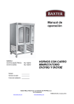
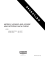
MODELS HO300G AND HO300E
MINI ROTATING RACK OVENS
MODEL
HO300E (ELECTRIC)
HO300G (GAS)
ML-132177
ML-132178
701 S. RIDGE AVENUE
TROY, OHIO 45374-0001
937 332-3000
www.hobartcorp.com
FORM 36705 (Oct. 2005)
IMPORTANT FOR YOUR SAFETY
THIS MANUAL HAS BEEN PREPARED FOR PERSONNEL QUALIFIED TO INSTALL GAS
EQUIPMENT, WHO SHOULD PERFORM THE INITIAL FIELD START-UP AND
ADJUSTMENTS OF THE EQUIPMENT COVERED BY THIS MANUAL.
POST IN A PROMINENT LOCATION THE INSTRUCTIONS TO BE FOLLOWED IN THE
EVENT THE SMELL OF GAS IS DETECTED. THIS INFORMATION SHOULD BE OBTAINED
FROM THE LOCAL GAS SUPPLIER.
IMPORTANT
IN THE EVENT A GAS ODOR IS DETECTED, SHUT DOWN
UNITS AT MAIN SHUTOFF VALVE AND CONTACT THE LOCAL
GAS COMPANY OR GAS SUPPLIER FOR SERVICE.
FOR YOUR SAFETY
DO NOT STORE OR USE GASOLINE OR OTHER FLAMMABLE
VAPORS OR LIQUIDS IN THE VICINITY OF THIS OR ANY
OTHER APPLIANCE.
WARNING: IMPROPER INSTALLATION, ADJUSTMENT,
ALTERATION, SERVICE OR MAINTENANCE CAN CAUSE
PROPERTY DAMAGE, INJURY OR DEATH. READ THE
INSTALLATION, OPERATING AND MAINTENANCE
INSTRUCTIONS THOROUGHLY BEFORE INSTALLING OR
SERVICING THIS EQUIPMENT.
IN THE EVENT OF A POWER FAILURE, DO NOT ATTEMPT TO
OPERATE THIS DEVICE.
KEEP AREA AROUND OVEN CLEAR OF COMBUSTIBLES. DO
NOT OBSTRUCT COMBUSTION AND VENTILATION OPENINGS
ON THE OVEN.
This manual has been prepared to provide information in accordance with
ANSI Z83.11-2004 for gas equipment.
© HOBART, 2005
–2–
TABLE OF CONTENTS
GENERAL .............................................................................................................................................4
INSTALLATION ....................................................................................................................................4
Unpacking ........................................................................................................................................4
Location ............................................................................................................................................5
Installation Codes and Standards ...................................................................................................5
Assembly ..........................................................................................................................................5
Gas Connections .............................................................................................................................6
Testing the Gas Supply System .....................................................................................................6
Ventilation .........................................................................................................................................6
Plumbing Connections .....................................................................................................................6
Drain Connections ...........................................................................................................................7
Electrical Connections ....................................................................................................................7
OPERATION .........................................................................................................................................8
Controls ............................................................................................................................................8
Setting Clock ..................................................................................................................................11
Basic Operation .............................................................................................................................12
Food Service Steam Mode ............................................................................................................ 14
Safety Alarm ...................................................................................................................................14
Programming the Oven .................................................................................................................15
Using the Programs .......................................................................................................................18
Customized Operation ................................................................................................................... 19
Shutdown ........................................................................................................................................22
Cleaning .........................................................................................................................................22
ACCESSORIES - HPC800 PROOFING CABINET .........................................................................23
Plumbing connections ................................................................................................................... 23
Drain connections .......................................................................................................................... 23
Electrical Connections ..................................................................................................................23
Dimensions and Service Connection Diagram ............................................................................24
Controls ..........................................................................................................................................25
MAINTENANCE ..................................................................................................................................26
General ........................................................................................................................................... 26
Parts and Service Information ......................................................................................................26
TROUBLESHOOTING .......................................................................................................................27
Burners Will Not Light (Gas Ovens Only) .................................................................................... 27
Safety Alarm ...................................................................................................................................27
Circulation Motor ............................................................................................................................27
Parts and Service Information ......................................................................................................27
OWNER PREVENTIVE MAINTENANCE PROCEDURES .............................................................28
Introduction .....................................................................................................................................28
Preventive Maintenance Procedures ........................................................................................... 28
–3–
OPERATION AND CARE OF
MODELS HO300G AND HO300E MINI ROTATING
RACK OVENS
KEEP THIS MANUAL FOR FUTURE USE
GENERAL
Models HO300G (Gas) and HO300E (Electric) Mini Rotating Rack Ovens feature the choice of two
rack configurations:
•
Eight 18" x 26" (45.7 cm x 66 cm) pan capacity rack with 4" (10.2 cm) slide spacing
•
Six 18" x 26" (45.7 cm x 66 cm) pan capacity rack with 5.31" (13.5 cm) slide spacing
Both oven rack options can be ordered in an end-load or side-load design. A mechanism in the ceiling
rotates the rack during baking.
Model HO300G is rated at 95,000 BTU/hr (natural or propane gas). Model HO300E is rated at 18.0 kW
(electric).
Hobart Mini Rotating Rack Ovens are produced with quality workmanship and material. Proper
installation, usage and maintenance of the rack oven will result in years of satisfactory performance.
It is suggested that you thoroughly read this manual and carefully follow the instructions provided.
INSTALLATION
In order to validate the warranty, the start-up must be performed by an Authorized Service Representative.
Before installing, verify that the electrical service(s) and type of gas supply (natural or propane) agree
with the specifications on the data plate located on top of the oven. If the supply and equipment
requirements do not agree, do not proceed with the installation. Contact Hobart Bakery Systems
immediately.
UNPACKING
This oven was inspected before leaving the factory. The transportation company assumes full
responsibility for safe delivery upon acceptance of the shipment. Immediately after unpacking, check
for possible shipping damage. If the oven is found to be damaged, save the packaging material and
contact the carrier within 15 days of delivery.
Carefully unpack the oven and place in a work-accessible area as near to its final installed position as
possible. Remove protective covering from exterior surfaces prior to placing oven in final location.
–4–
LOCATION
The HO300G and HO300E Mini Rotating Rack Ovens must have the following minimum clearances
to combustibles:
•
Back and sides: 0"
•
Bottom: 0"
•
Top: 18" (45.7 cm)
NOTE: Minimum 24" clearance needed for service access on the right side. If right side is within 30"
of radiant heat or grease vapor source, vent guard is required.
Be sure that electrical, water and drain connections are accessible and can be made per local and
national codes. The equipment area must be kept free and clear of combustible substances.
Do not obstruct the flow of combustion and ventilation air. Adequate clearance for air openings into the
combustion chamber must be provided. Make sure there is an adequate supply of air in the room to
replace air taken out by the ventilating system.
INSTALLATION CODES AND STANDARDS
The oven must be installed in accordance with:
In the United States of America:
1. State and local codes.
2. National Fuel Gas Code, ANSI-Z223.1 (latest edition). Copies may be obtained from The
American Gas Association, Inc., 1515 Wilson Blvd., Arlington, VA 22209.
3. National Electrical Code, ANSI/NFPA-70 (latest edition).
In Canada:
1. Local codes.
2. CAN/CGA-B149.1 Natural Gas Installation Code (latest edition).
3. CAN/CGA-B149.1 National Fuel Gas Code (latest edition), available from The Canadian Gas
Association, 178 Rexdale Blvd., Etobicoke, Ontario, Canada M9W 1R3.
ASSEMBLY
The oven must be installed on a stand, proofer cabinet or any noncombustible surface.
The oven must be sealed to the stand, proofer cabinet or surface with an NSF-approved sealant, such
as Dow Corning 732 or GE RTV108.
Secure the oven to the proofer or stand using the provided tie-down brackets, which mount on the rear
of the oven. (See Accessories - HPC800 Proofing Cabinet for proofer specifications.)
Oven Mounted on a Stand or Proofer with Caster
For an appliance equipped with casters, instructions that (1) the installation shall be made with a
connector that complies with the Standard for Connectors for Movable Gas Appliances, ANSI Z21.69
or Connectors for Moveable Gas Appliances, CAN/CGA-6.16, and a quick-disconnect device that
complies with the Standard for Quick-Disconnect Devices for Use With Gas Fuel, ANSI Z21.41, or
Quick Disconnect Devices for Use with Gas Fuel, CAN1-6.9, (2) adequate means must be provided
to limit the movement of the appliance.
–5–
GAS CONNECTIONS
CAUTION: Gas supply connections and any pipe joint compound must be resistant to the
action of propane gases.
The HO300G is an indirect gas-fired oven, consisting of a heat exchanger with eight independent,
U-shaped tubes, each with a separate in-shot burner rated at 11,875 BTU/hr for a total input of
95,000 BTU/hr.
WARNING: PRIOR TO LIGHTING, CHECK ALL JOINTS IN THE GAS SUPPLY LINE FOR LEAKS.
USE SOAP AND WATER SOLUTION. DO NOT USE AN OPEN FLAME.
TESTING THE GAS SUPPLY SYSTEM
When gas supply pressure exceeds 1/2 psig (3.45 kPa), the oven and its individual shutoff valve must
be disconnected from the gas supply piping system.
When gas supply pressure is 1/2 psig (3.45 kPa) or less, the oven should be isolated from the gas supply
system by closing its individual manual shutoff valve.
VENTILATION
Information on the construction and installation of ventilating hoods may be obtained from the standard
for Vapor Removal from Cooking Equipment, NFPA No. 96 (latest edition), available from the National
Fire Protection Association, Batterymarch Park, Quincy, MA 02269.
Exhaust Fan Interlock
A connection point (maximum 5-amps) is provided for Indirect Vent (Exhaust Hood) or optional Direct
Vent (Draft Hood). It is located behind the right side service panel adjacent to the 120 V power
connection. Consult local codes for vent interlock requirements.
Indirect Vent (Under Exhaust Hood) - Standard
Locate the oven under an exhaust hood with adequate overhangs and exhaust rates to completely
capture the byproducts of combustion discharged from the flue. From the termination of the flue to the
filters of the hood venting system, a minimum clearance of 18" must be maintained. The hood exhaust
fan must be electrically interlocked with the oven.
PLUMBING CONNECTIONS
WARNING: PLUMBING CONNECTIONS MUST COMPLY WITH APPLICABLE SANITARY, SAFETY
AND PLUMBING CODES.
Oven water supply should have a hardness of 4 to 6 grains per gallon, pH of 6.5 to 8.0 and chlorides
less than 30 PPM. Water condition outside of these requirements may void the warranty. Please
consult your local water company and/or water condition dealer before installing oven.
Connect the cold water supply to the 1/2" NPT incoming water connection located at the rear of the oven,
with the 6-ft, flexible, clear, water line provided. Water supply should have a pressure of 30 to 75 psi
(207 to 517 kPa) when the steam solenoid is open.
–6–
DRAIN CONNECTIONS
Connect a 1/2" drain line to the 1/2" NPT drain connection located at the rear of the oven. Route the drain
line to a floor drain, allowing a minimum 1" air gap between the drain line outlet and floor drain.
If oven is being installed on an HPC800 Proofing Cabinet, it is recommended that separate drain lines
be provided. If it is necessary to interconnect the oven and proofer drains, provide a vent opening in
the drain line above the oven drain connection location. Adequate drop must be provided such that the
oven drain will not flood the proofer cabinet.
ELECTRICAL CONNECTIONS
WARNING: ELECTRICAL AND GROUNDING CONNECTIONS MUST COMPLY WITH THE
APPLICABLE PORTIONS OF THE NATIONAL ELECTRICAL CODE AND/OR OTHER LOCAL
ELECTRICAL CODES.
WARNING: DISCONNECT THE ELECTRICAL POWER TO THE MACHINE AND FOLLOW
LOCKOUT / TAGOUT PROCEDURES.
WARNING: APPLIANCES EQUIPPED WITH A FLEXIBLE ELECTRIC SUPPLY CORD ARE
PROVIDED WITH A THREE-PRONG GROUNDING PLUG. THIS PLUG MUST BE CONNECTED
INTO A PROPERLY GROUNDED THREE-PRONG RECEPTACLE. IF THE RECEPTACLE IS NOT
THE PROPER GROUNDING TYPE, CONTACT AN ELECTRICIAN. DO NOT REMOVE THE
GROUNDING PRONG FROM THIS PLUG.
The wiring diagram is located behind the side service panel on the right side of the oven.
Do not connect the HO300G gas model to the electrical supply until after gas connections have been
made.
The HO300E is an electrically heated oven consisting of six W-shaped elements, each rated at 3.0 kW
for a total input of 18.0 kW. The electrical input is shown in the table below:
Heating Circuit Supply Voltage
Both gas and electric ovens require a dedicated 15-amp, 110 V 50 Hz or 120 V 60 Hz, single-phase
supply with ground, connected at the control circuit terminal block located behind the right side service
panel. If oven is installed in conjunction with an HPC800 Proofing Cabinet, a separate 120 V supply
is required for the proofer.
–7–
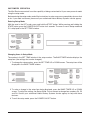
OPERATION
WARNING: THE MINI-RACK OVEN AND ITS PARTS ARE HOT. USE CARE WHEN OPERATING,
SERVICING OR CLEANING THE OVEN.
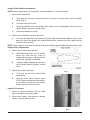
CONTROLS
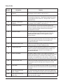
–8–
Control Guide
Button
POWER
Action
Display
Press to turn the oven
ON or OFF.
Control panel displays are lit when the oven is on. Oven
defaults to Program 0. If oven is turned OFF and back
ON within 2 minutes, the oven will come up in the last
mode and oven setting.
AUTO ON/OFF
TIMER
Press to enter current time
or time for oven to
automatically turn ON or
OFF, when corresponding
Auto On Time or Auto Off
Time button is pressed.
The AUTO ON/OFF TIMER window displays the current
time or the time the oven will automatically turn ON or
OFF.
AUTO ON TIME
Press arrow keys to set
the desired time of oven to
automatically turn ON.
The AUTO ON/OFF TIMER window displays the time
the oven will automatically turn ON.
AUTO OFF TIME
Press arrow keys to set
the desired time of oven to
automatically turn OFF.
The AUTO ON/OFF TIMER window displays the time
the oven will automatically turn OFF.
TIMER ON/OFF
Press to turn the automatic
timer ON or OFF.
The indicator light beside the timer ON/OFF button is
lit when the function is enabled.
SET TEMP
Use to enter bake programs.
The SET TEMP window displays the set temperature.
The heat ON light is lit while the oven is heating. The
actual temperature in the oven cavity is displayed in the
OVEN TEMP window.
Press arrow keys to enter
the BAKE time
(1 minute increments).
Press the up arrow key
to enter additional time
at the end of the bake
program.
The BAKE TIMER window displays the amount of time
for the current baking cycle. The minutes set are the
left two digits and minutes remaining are the right two
digits. The windows can be set to display hours and
minutes remaining. The ON light is lit when bake time
is active.
STEAM TIMER
Press to enter the STEAM
time (5-second increments
in Bakery mode; 1-second
increments in Food Service
mode).
The STEAM TIMER window displays the amount of
time set for the steam cycle. The ON light is lit when
the steam system is active.
AIRFLOW
DELAY
Press to enter into beginning
of baking cycle.
The DELAY TIMER window displays the amount of
time set for the circulation blower delay cycle
0-9 minutes.
Press to start the
BAKE TIMER.
The ON light blinks when the BAKE TIMER is active.
BAKE TIMER
–9–
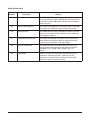
Control Guide (cont)
Button
PROGRAM
STEP
Action
Display
Press to stop the BAKE
TIMER or silence the
beeper after the BAKE
TIMER has timed out.
The ON light is off when the BAKE TIMER is inactive.
Press the
arrow keys to select
a bake program.
The PROGRAM window displays the number of the
current program.
Use to enter bake programs.
The corresponding indicator light will be lit (1 to 4),
depending on which step is selected.
Press to open or
close the vent.
The indicator light next to the VENT button is lit when
the vent cycle is enabled.
Use to cool down the oven.
To enable this feature, set a temperature at least
25°F (14°C) cooler than the oven temperature. Press
the COOL DOWN button. The COOL DOWN mode is
exited when the oven reaches the new set temperature,
or if door is opened when temperature is 25°F (14°C)
below set temperature, or by pressing any button.
– 10 –
Auto ON/OFF Timer
Setting Clock
Auto ON/OFF Timer display shows the current time of day. To set the clock, the control must be turned
on. Press and hold either of the arrow buttons until the colon between the hours and minutes display
stops blinking. Use the up and down arrow buttons to adjust time of day. After 5 seconds of no use, the
colon will start to blink again.
The oven can be set to turn itself on and off. After the Auto ON/OFF Timer is set, the POWER ON OFF
button can be pressed to turn the oven off. This will not disrupt the AUTO ON/OFF setting. Electrical
power to the oven must remain on.
1. To set the oven to turn on, press and hold the AUTO ON TIME button. The previously entered start
time will appear in the display. Use the UP and DOWN arrows to adjust the start time. Then
release the AUTO ON TIME button.
2. To set the oven to turn off, press and hold the AUTO OFF TIME button. The previously entered
end time will appear in the display. Use the UP and DOWN arrows to adjust the end time. Then
release the AUTO ON TIME button.
3. To enable the automatic start, press the TIMER ON/OFF button until the indicator LED to the right
of the TIMER ON/OFF button is illuminated.
Backup Battery
The clock is backed up by a lithium battery which keeps the clock circuitry operating when all external
power is off. If the battery becomes low or dead while the external power is off, the display will read
12:00 (12 hr mode) or 0:00 (24 hr mode) and will not increment until a new time is set. The clock will
operate with a dead or missing battery, but must be set each time external power is turned on. Batteries
should be replaced when low or dead to avoid corrosive damage to the circuitry.
– 11 –
Oven Preheat
For best results, the oven must be preheated to bake temperature before baking begins.
1. Press the POWER ON OFF button to turn the oven ON.
2. Press the UP or DOWN arrows in the TEMP section to enter the desired baking temperature.
3. Confirm that the doors are closed.
4. Allow 50 minutes after the oven has reached the set temperature for the steam system to charge.
5. The oven is now ready for baking operations.
Basic Operation
WARNING: THE OVEN AND ITS PARTS ARE HOT. TO PREVENT BURNS, USE HOT PADS OR
PROTECTIVE MITTS WHEN LOADING OR UNLOADING THE OVEN.
WARNING: HOT AIR AND STEAM ARE RELEASED FROM THE OVEN INTERIOR WHEN THE
LOADING DOORS ARE OPENED. TO AVOID BURNS, OPEN THE DOORS SLOWLY AND KEEP
CLEAR OF THE OPENING.
1. Preheat the oven. See Oven Preheat.
2. Manually select baking settings:
•
Press the UP or DOWN arrows next to BAKE TIMER to enter the desired value.
•
Press the UP or DOWN arrows next to STEAM TIMER to enter the desired value.
•
Press the UP arrow next to AIRFLOW DELAY to enter the desired value.
•
The steam and airflow delay settings are optional and can be left at 0 if desired.
3. Slowly open the doors. Wait for the rack to stop. Load the oven. Close the doors.
4. Press the START button. The ON light in the BAKE TIMER window blinks until the timer times out.
5. The oven beeps after the BAKE TIMER times out. Press STOP to silence the beeper.
– 12 –
Operational Hints
•
On the initial startup, the oven temperature will default to the factory setting of 375°F (191°C)
unless changed using customized operations.
•
During a baking cycle, the START and STOP buttons control the BAKE, STEAM and AIRFLOW
DELAY settings only. They have no effect on the oven heat. When the BAKE TIMER times out,
the oven heat stays at the set temperature. Care should be taken not to overbake products.
•
To adjust the temperature during a baking cycle, press the UP or DOWN arrows in the Oven
Temp section to enter the new temperature.
•
To adjust the BAKE, STEAM and AIRFLOW DELAY settings, press the corresponding arrows
to enter the new values. Press START when finished.
•
Circulation blower will pulse during a steam cycle to assist steam distribution. It does not attain
full speed.
•
If the doors are opened at any time during the baking cycle, the TEMP, BAKE TIME, STEAM
and AIRFLOW DELAY settings will pause. Close the doors to resume all functions.
•
The AIRFLOW DELAY option minimizes airflow at the beginning of the baking cycle. The heat
is off while the AIRFLOW DELAY is activated.
•
If the oven temperature is more than 20°F (11°C) higher than the set temperature, and the bake
timer is not activated, the oven will automatically open the VENT. The VENT will remain open
until the oven temperature is within 20°F (11°C) of the set temperature.
•
The oven monitors the heating system by comparing the current oven temperature to the set
temperature. If a problem arises in the heating system or there is a heating system failure, both
temperature displays will flash. If the problem continues, contact your authorized Bakery
Systems service agency.
•
The COOL DOWN feature provides a means of cooling down the oven. To enable this feature,
set a temperature at least 25°F (14°C) cooler than the oven temperature. Press the COOL
DOWN button—the display alternately shows the set temperature and COOL and the vent
opens. Additionally, the doors can be opened and the circulation fan will continue to run. The
COOL DOWN mode is exited by the oven temperature reaching set temperature (25°F (14°C)
below set temperature if doors are opened) or by pressing any button.
•
The oven rack will rotate only after there is time entered into the bake timer and the start button
has been pressed. Rotation will start when both doors are closed. If there is no time entered into
the bake timer, the display will flash. Press STOP and the controller will stop flashing. Once
started, the rack will continue to rotate until a door is opened.
•
Circulation fan will stop running if the oven set point is reached and there is no ("0") time
displayed on the controller.
– 13 –
FOOD SERVICE STEAM MODE
This mode can be used to provide steam on a periodic basis throughout operation. When this mode is
enabled, the STEAM TIMER controls how many seconds of steam are provided to the oven, while a
value entered in the Parameter 14 (P14) setup controls how frequently the steam is operated.
To enable the Food Service Steam mode:
1. Enter the parameter setup mode. (See Entering Setup Mode.)
2. Select Parameter 14.
3. If the BAKE TIMER window displays ‘0’, it is set up for Bakery Mode (factory default). Press the
UP or DOWN arrow buttons to enter FSS mode (display will change to a 3-digit number).
4. Set the desired time between steam cycles using the UP or DOWN arrow buttons. The range is
from 300 seconds (5 min.) to 990 seconds (approximately 17 min.), and increments by 10
seconds at a time.
5. After setting the desired cycle, press the POWER ON OFF button to save the settings.
6. The STEAM TIMER will now operate in 1-second increments, up to 10 seconds, to set the duration
of steaming.
Examples:
‘300’ is selected for P14
‘3’ is entered in STEAM TIMER
= steam is turned on for 3 seconds every 300 seconds (5 min.)
‘990’ is selected for P14
‘3’ is entered in STEAM TIMER
= steam is turned on for 3 seconds every 990 seconds (17 min.)
To return the oven to Bakery Mode, repeat the above process to access P14 and set the value in the
BAKE TIMER window to ‘0’. The STEAM TIMER will now operate in 5-second increments.
SAFETY ALARM (STANDARD FEATURE, NO PARAMETER SETUP REQUIRED)
If the temperature at the probe is in the range of 570 - 600 degrees Fahrenheit for 10 seconds, the unit
will do the following:
1. Shut off all features.
2. Sound an alarm.
3. Flash the OVEN TEMP display (actual temperature is displayed).
4. Display the letters ‘SHdn’ in the BAKE TIMER display.
WARNING: DISCONNECT THE ELECTRICAL POWER TO THE MACHINE AND FOLLOW
LOCKOUT / TAGOUT PROCEDURES. THERE MAY BE MULTIPLE CIRCUITS. BE SURE ALL
CIRCUITS ARE DISCONNECTED.
WARNING: IF GAS OVEN, SHUT OFF GAS. CONTACT YOUR AUTHORIZED HOBART BAKERY
SYSTEMS SERVICE OFFICE. DO NOT ATTEMPT TO RESTART THE OVEN UNTIL IT HAS BEEN
INSPECTED BY AN AUTHORIZED SERVICER.
– 14 –
PROGRAMMING THE OVEN
Single Step Programming
The program menu stores up to 99 programs that can be recalled by number when needed. A program
is a set of baking instructions (temperature, bake, steam and airflow delay settings) that the operator
defines for any baking operation.
1. With the oven in the OFF mode, press and hold the UP arrow in the STEPS section. While
pressing and holding the UP arrow, press the POWER ON OFF button for 3 seconds. When the beep
sounds, the oven is in program mode.
2. Press the PROGRAM UP or DOWN arrows until the program number that is desired is displayed.
3. Press the TEMP UP or DOWN arrows to enter the desired temperature.
4. Set the Bake, Steam, Delay Airflow and Vent settings:
•
Press the UP or DOWN arrows next to BAKE TIMER to enter the desired time.
•
Press the UP or DOWN arrows next to STEAM TIMER to enter the desired time.
•
Press the UP arrow next to AIRFLOW DELAY to enter the desired time.
NOTE: Steam and airflow delay settings are optional and can be left at 0 if desired.
•
Press the VENT button to vent the cavity for the entire time of the step. When step is
complete, vent will close.
5. To store the program, press the PROGRAM UP or DOWN arrows to move to the next program
number or press the POWER ON OFF button to exit the program mode. To store additional program
settings, repeat steps 2 to 4.
6. Record program numbers and product associated with them.
– 15 –
Multi-Step Programming
Additional programs or steps can be entered within the original program number. Up to four individual
steps can be added by the operator, each with different bake settings.
For example, Program 1 has temperature, bake, steam and delay time settings set by the operator. This
is known as Step 1. After the timer times out in Step 1, the oven automatically starts the programmed
bake settings in Step 2. The system continues with each step until all steps have been timed out.
1. With the oven in the OFF mode, press and hold the UP arrow in the STEPS section. While
pressing and holding the UP arrow, press the POWER ON OFF button for 3 seconds. When the
beep sounds, the oven is in program mode.
2. Press the PROGRAM UP or DOWN arrows until the program number that is desired is displayed.
The Step 1 light is lit.
3. Press the TEMP UP or DOWN arrows to enter the desired temperature.
4. Set the Bake, Steam, Delay Airflow and Vent settings:
•
•
•
Press the UP or DOWN arrows next to BAKE TIMER to enter the desired time.
Press the UP or DOWN arrows next to STEAM TIMER to enter the desired time.
Press the UP arrow next to AIRFLOW DELAY to enter the desired time.
NOTE: The steam and airflow delay settings are optional and can be left at 0 if desired.
•
Press the VENT button to vent the cavity for the entire time of the step. When step is
complete, vent will close.
5. Press the UP arrow in the STEPS section to advance to the next step within the program. The
selected step light is lit. Repeat steps 3 and 4 above to set each step, if needed, in the program.
6. To store all the steps in the program, press the PROGRAM UP or DOWN arrows to move to the
next program number, or press the POWER ON OFF button to exit the program mode.
– 16 –
Changing the Programs
1. With the oven in the OFF mode, press and hold the UP arrow in the STEPS section. While
pressing and holding the UP arrow, press the POWER ON button for 3 seconds. When the beep
sounds, the oven is in program mode.
2. Press the PROGRAM UP or DOWN arrows until the program number that is desired is displayed.
3. Enter the new Bake, Steam and Delay Airflow settings:
•
Press the UP or DOWN arrows next to BAKE TIMER to enter the desired time.
•
Press the UP or DOWN arrows next to STEAM TIMER to enter the desired time.
•
Press the UP arrow next to AIRFLOW DELAY to enter the desired time.
NOTE: The steam and airflow delay settings are optional and can be left at 0 if desired.
4. To change the settings in a Step, press the UP arrow in the STEPS section and make changes
in each step accordingly.
5. To store the program, press the PROGRAM UP or DOWN arrows to move to the next program
number or press the POWER ON OFF button to exit the program mode.
– 17 –
USING THE PROGRAMS
1. Press the PROGRAM UP or DOWN arrows to select the desired program number (1-99). The
TEMP, BAKE, STEAM and AIRFLOW DELAY settings are displayed.
2. Confirm that the oven is at the set baking temperature.
3. Slowly open the doors. Wait for the rack to come to a stop.
4. Load product into oven.
5. Close the doors.
6. Press START. A beeper will sound after the BAKE TIMER times out. Press STOP to silence the
beeper.
7. Check product for doneness.
IF NOT DONE — If more bake time is needed, press the Bake Timer UP ARROW key until the
desired time appears on the Minutes Set window. Press the START Key. The
Timer On indicator light will start blinking.
IF DONE — Allow rack to stop and remove pans.
Program Hints
•
The oven defaults to the Program 0 settings when first turned on. Program 0 settings are as
follows: Temp = 375°F, Bake Timer = 0, Steam Timer = 0, Delay Timer = 0, Program = 0.
•
Any combination of bake settings can be manually entered for one-time custom baking
operations. These settings are not saved to the program memory.
•
If any of the baking parameters are changed in a program before or during a bake cycle, the oven
reverts to a manual program (Program 0) indicating that the program has been altered. The oven
will continue to operate all the program steps as displayed.
•
The PROGRAM UP and DOWN arrows have no effect while the bake cycle is in progress.
However, if the BAKE TIMER has been stopped, either by pressing the STOP button or by
opening the door, then pressing the PROGRAM UP and DOWN arrows will select a new
program and cancel the baking cycle that was in progress.
•
When selecting programs, the system will skip over unprogrammed numbers. For example, if
Program 1 is displayed in the PROGRAM window and no programs are stored in 2, 3 and 4, then
the system will skip over 2, 3 and 4. Program 5 will be the next program displayed.
•
Vent opening programs the vent to open for "P10" seconds full open and then for "P11" seconds
every 60 seconds.
– 18 –
CUSTOMIZED OPERATION
The Mini-Rack oven controls have the capability of being customized to fit your own personal needs
using the setup mode.
Before entering the setup mode, read all the instructions to make sure you are completely clear on what
to do. If you need assistance, please call your authorized Hobart Bakery Systems service agency.
Entering Setup Mode
With the oven in the OFF mode, press and hold the START button. While pressing and holding the
START button, press the POWER ON OFF button for 3 seconds. The oven is now in Setup mode and
P1 is displayed in the SET TEMP window.
Changing Items in Setup Mode
The number in the SET TEMP window is the setup number. The BAKE TIMER window displays the
setup item (the settings that can be changed).
1. To change the setup number, press the SET TEMP UP or DOWN arrows. The setup item will be
displayed in the BAKE TIMER window.
2. To make a change in the setup item being displayed, press the BAKE TIMER UP or DOWN
arrows. To adjust the setting, see Setup Guide. Do not attempt to change item numbers P4, P5
and P8. Consult your authorized Hobart Bakery Systems service agency for help with these
features.
3. To exit the setup mode, press the POWER ON OFF button.
– 19 –
Setup Guide
Setup
Number
Setup Item
Display
P1
Maximum Temperature
Setpoint
This is the maximum temperature at which the oven can be
set. Range is 50°F to 525°F (10°C to 274°C).
P2
Preheat Temperature
This is the default temperature setpoint when the oven is
first turned on (Program 0). The preheat temperature cannot
be set higher than the value in P1. Range is 50°F to 525°F
(10°C to 274°C).
P3
Minimum Temperature
Setpoint
This is the minimum temperature at which the oven can be
set. Range is 50°F to 200°F (10°C to 93°C).
P4
Temperature Offset
This value permits an offset of correction between the
temperature probe and the real baking chamber temperature.
Call your authorized Bakery Systems service agency
for help with this feature.
P5
Heat OFF Offset
This value adjusts the temperature difference between the
set point and stopping of the heating system. Call your
authorized Bakery Systems service agency for help
with this feature.
P6
Heat Difference Hysteresis
This value adjusts the temperature difference between the on
temperature and off temperature of the heating system. Call
your authorized Bakery Systems service agency for
help with this feature.
P7
Maximum Steam Time
Time set is the maximum time (in seconds) that water is
supplied during the STEAM TIMER operation.
P8
Temperature Units
The oven can be set to display temperature in Fahrenheit or
Celsius. To ensure accurate temperature parameters, call
your authorized Bakery Systems service agency for
help with this feature.
P9
Bake Timer Mode
The BAKE TIMER can be set up to display minutes set/
minutes remaining or hours and minutes. Select 0 for minutes
set/minutes remaining or 1 for hours and minutes. (If this
parameter is changed to hours and minutes, a label has been
provided to place on the control panel to indicate the change.)
P10
Vent Evacuate Time
Time set is the time (in seconds) that the vent is 100% open
at the beginning of the venting cycle. Range is 0 to 180
seconds.
P11
Vent Open
This value is the seconds the bake chamber vent is open per
60 seconds after the vent evacuate time has expired. Range
is 5 to 59.
P12
End of Bake Automatic
Vent - Enable
This feature enables the Automatic Vent Cycle. Select 0 to
disable or 1 to enable this feature (see P13 for entering time).
P13
End of Bake Automatic
Vent Time
This is the number of minutes before the end of the bake
cycle that the vent is open.
– 20 –
Setup Guide (cont)
Setup
Number
Setup Item
Display
P14
Steam Timer Mode
The STEAM TIMER can be set up to function in Bakery mode
"0" (single steam function at the beginning of step/cycle) or
Food Service mode "300 to 990" seconds interval between
steam functions.
P15
Interior Light Brightness
This value is the brightness of the interior lights. The higher
the number, the brighter the lights. Range is 50 to 100.
P16
Clock Operation
This selects either 12 hours (AM/PM) or 24 hours real time
display. Press the Bake Time Up button to switch between
the two types of display.
P17
Temperature Setback Time
This selects the elapsed time from the last timed bake to
when the oven will lower the oven set temperature to the
value set in P18. Range is 10 to 180 minutes.
P18
Setback Temperature
This selects the oven set temperature that the oven will
change to when the temperature setback time has been
exceeded in P17. Range is 50°F to 300°F (10°C to
149°C).
P19
Lights Mode
Select 1 for lights on continuously (when oven is on) or
select 0 for automatic operation. Lights will turn off
automatically after 30 minutes of no user activity (door
opened or closed, no buttons pushed).
– 21 –
SHUTDOWN
NOTE: Before restarting a gas oven, power and gas burner valve must be off for a minimum of
5 minutes.
1. Remove all remaining product.
NOTE: Vent can be used to evacuate steam from oven.
2. Allow the oven to cool, then press the POWER ON OFF button.
3. Clean the baking chamber. (See Cleaning.)
4. For lengthy shutdowns, disconnect the main power and shut off the gas and water supply.
CLEANING
WARNING: THE MINI-RACK OVEN AND ITS PARTS ARE HOT. USE CARE WHEN OPERATING,
SERVICING OR CLEANING THE RACK OVEN.
WARNING: DISCONNECT THE ELECTRICAL POWER TO THE OVEN AND FOLLOW
LOCKOUT / TAGOUT PROCEDURES.
•
Allow the oven to cool.
•
Clean the outside of the oven daily with a clean, damp cloth.
•
Clean rack as you would any cooking utensil. Use warm, soapy water and a brush. Rinse with
clean water and dry with a clean cloth.
•
Use care when cleaning around sensitive interior parts, such as probes, sensors or the rotating
mechanism.
•
Gently scrape heavy buildup off door glass. Residue can be removed with a glass cleaner when
oven is cool.
•
Do not use cleaners containing grit, abrasive materials, bleach, harsh chemicals or chlorinated
cleaners. Do not use oven cleaners. Do not use steel wool or stainless steel cleaners on
stainless steel surfaces. Stainless steel polish can be used on the exterior of the oven, never
on the interior. When polishing, follow the grain of the stainless steel.
•
Never spray down the oven with water or steam.
•
Be cautious with new or improved cleaning formulas; use only after being well tested.
•
To rapidly cool down the oven, shut off the controller. Open both doors and press the vent
button. This will run the circulation blower without any heat input until the door is closed.
– 22 –
ACCESSORIES - HPC800 PROOFING CABINET
The HO300 Mini Rotating Rack Oven can be ordered with the optional HPC800 Proofing Cabinet. The
proofer is mounted on four casters (two front-swivel and two rear-fixed).
The HPC800 Proofer has a 16-pan capacity that accommodates 18" x 26" (45.7 cm x 66 cm) baking
trays with 3" (7.6 cm) slide spacing. Temperature and humidity can be set independently to meet your
particular proofing needs. Air is circulated continuously to provide positive movement from bottom to
top, creating a uniform distribution of warm, moist air.
All HPC800 Proofers have easy-to-clean stainless steel interior and exterior panels with urethane foam
insulation.
PLUMBING CONNECTIONS
WARNING: PLUMBING CONNECTIONS MUST COMPLY WITH APPLICABLE SANITARY, SAFETY
AND PLUMBING CODES.
The proofer should have its own water supply line, separate from the oven.
The proofer water supply should have a hardness of 4 to 6 grains per gallon, pH of 6.5 to 8.0 and
chlorides less than 30 PPM. Water condition outside of these requirements may void the warranty.
Please consult your local water company and/or water condition dealer before installing proofer.
Connect the cold water supply to the 3/8" NPT incoming water connection, located at the rear of the
proofer. Water supply should have a pressure of 30 to 75 psi.
DRAIN CONNECTIONS
Connect a 1/2" drain line to the 1/2" NPT drain connection located at the rear of the proofer. Route the drain
line to a floor drain, allowing a minimum 1" air gap between the drain line outlet and floor drain.
Provide a vent opening in the drain line above the oven drain connection location.
ELECTRICAL CONNECTIONS
WARNING: ELECTRICAL AND GROUNDING CONNECTIONS MUST COMPLY WITH THE
APPLICABLE PORTIONS OF THE NATIONAL ELECTRICAL CODE AND/OR OTHER LOCAL
ELECTRICAL CODES.
WARNING: DISCONNECT THE ELECTRICAL POWER TO THE OVEN AND FOLLOW
LOCKOUT / TAGOUT PROCEDURES.
WARNING: APPLIANCES EQUIPPED WITH A FLEXIBLE ELECTRIC SUPPLY CORD ARE
PROVIDED WITH A THREE-PRONG GROUNDING PLUG. THIS PLUG MUST BE CONNECTED
INTO A PROPERLY GROUNDED THREE-PRONG RECEPTACLE. IF THE RECEPTACLE IS NOT
THE PROPER GROUNDING TYPE, CONTACT AN ELECTRICIAN. DO NOT REMOVE THE
GROUNDING PRONG FROM THIS PLUG.
– 23 –
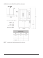
DIMENSIONS AND SERVICE CONNECTION DIAGRAM
NOTE: The proofer must be wired separately from the oven.
– 24 –
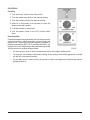
CONTROLS
Proofing
1. Turn the power switch to the ON position.
2. Turn the temperature knob to the desired setting.
3. Turn the humidity knob to the desired setting.
4. Allow 15 to 20 minutes for the proofer to reach set
temperature and humidity.
5. Load the product in the proofer.
6. Turn the power switch to the OFF position when
done.
Proofing Hints
Controlled temperature and humidity in the proofer promotes
yeast fermentation, which generates gas and causes the
dough to rise. Proofing will vary from product to product. A
temperature setting of 95°F (35°C) and humidity at 85% are
typical but will vary, depending on the product being proofed
and the amount of product being proofed.
•
For best results, proof at lower temperatures rather than higher temperatures.
•
To dry proof, set humidity to the lowest setting. At this setting, the humidity generator is turned
off and will not produce humidity.
•
For the best results, always allow your proofer to reach set temperature and humidity before
putting product in.
– 25 –
MAINTENANCE
WARNING: THE MINI-RACK OVEN AND ITS PARTS ARE HOT. USE CARE WHEN OPERATING,
SERVICING OR CLEANING THE OVEN.
WARNING: DISCONNECT THE ELECTRICAL POWER TO THE OVEN AND FOLLOW
LOCKOUT / TAGOUT PROCEDURES.
GENERAL
As Needed
•
Inspect the area around the oven. The area must be free and clear from combustibles. There
must be no obstructions to the air flow.
Daily
•
Clean exterior. (See Cleaning.)
Weekly
NOTE: Do not change air shutter settings when cleaning oven interior.
•
Clean the oven interior and remove loose debris. (See Cleaning.)
•
Clean the windows.
Bi-Monthly
•
Owner Preventive Maintenance Procedures
Preventive Maintenance
The mini-rack oven should be kept on a regular preventive maintenance schedule. Ovens require
specific preventive maintenance based on usage and environmental factors. The failure to have the
oven properly maintained by following recommended preventive maintenance procedures may result
in higher repair costs, shortened equipment life or unsafe operating conditions.
The performance of routine preventive maintenance on any rack oven, which is the owner’s responsibility,
will help to ensure continued safe and reliable operation.
A preventive maintenance program is your best option for continued safe and reliable oven operation.
We believe that Hobart Bakery System Service is your best choice for performing preventive
maintenance.
PARTS AND SERVICE INFORMATION
Contact your authorized Hobart Bakery Systems service agency.
– 26 –
TROUBLESHOOTING
The oven has been set at the factory to bake assorted product, such as bagels, cookies and muffins.
If your bake is uneven, the shutters may need to be adjusted to achieve the desired results. Contact
your authorized Hobart Bakery Systems service agency for assistance.
BURNERS WILL NOT LIGHT (GAS OVENS ONLY)
1. Press the ON/OFF button to turn the power OFF and wait 5 minutes.
2. Make sure the gas shutoff valve is in the ON position.
3. Press the ON/OFF button to turn the oven ON.
If the oven does not light on the second attempt, turn the gas shutoff valve to the OFF position and call
your authorized Hobart Bakery System service agency.
SAFETY ALARM (STANDARD FEATURE, NO PARAMETER SETUP REQUIRED)
If the temperature at the probe is in range of 570 to 600°F for 10 seconds, the unit will do the following:
1. Shut off all features.
2. Sound an alarm.
3. Flash the OVEN TEMP display (actual temperature is displayed).
4. Display the letters 'SHdn' in the BAKE TIMER display.
WARNING: DISCONNECT THE ELECTRICAL POWER TO THE OVEN AND FOLLOW
LOCKOUT / TAGOUT PROCEDURES. THERE MAY BE MULTIPLE CIRCUITS. BE SURE ALL
CIRCUITS ARE DISCONNECTED.
WARNING: IF GAS OVEN, SHUT OFF GAS. CONTACT YOUR AUTHORIZED BAKERY SYSTEMS
SERVICE OFFICE. DO NOT ATTEMPT TO RESTART THE OVEN UNTIL IT HAS BEEN INSPECTED
BY AN AUTHORIZED SERVICER.
CIRCULATION MOTOR
To conserve energy, if there is no bake time (0) entered, the circulation blower will only run when oven
is below set point and burner/heaters are on.
RACK ROTATION
The rack will not rotate if no time "0" is set and started.
Check to make certain that doors are properly closed.
PARTS AND SERVICE INFORMATION
Contact your authorized Hobart Bakery Systems service agency.
– 27 –
OWNER PREVENTIVE MAINTENANCE PROCEDURES
INTRODUCTION
This customer preventive maintenance (PM) section includes procedures to inspect for proper
operation and cleaning of components. Owner Preventive Maintenance Procedures are written for gas
ovens. They can also be used for electric ovens by omitting the steps that refer to components found
only on gas ovens. Customer PMs should be conducted bi-monthly per OSHA Bakery Oven Inspection
Standard 29 CFR 1910.263(l)(9)(ii). A convenient PM Checklist is provided at the end of this section.
NOTE: This PM procedure does not discuss repair or replacement of components. Upon completion
of the PM procedure, you will need to contact a Hobart Bakery System service agency for any needed
repairs.
Tools Used For Inspection Procedure
•
Standard set of hand tools
•
Vacuum cleaner - shop vac
PREVENTIVE MAINTENANCE PROCEDURES
WARNING: DISCONNECT THE ELECTRICAL POWER TO THE OVEN AND FOLLOW
LOCKOUT / TAGOUT PROCEDURES.
WARNING: SHUT OFF THE GAS BEFORE SERVICING THE UNIT.
WARNING: CERTAIN PROCEDURES IN THIS SECTION REQUIRE ELECTRICAL TEST OR
MEASUREMENTS WHILE POWER IS APPLIED TO THE MACHINE. EXERCISE EXTREME
CAUTION AT ALL TIMES. IF TEST POINTS ARE NOT EASILY ACCESSIBLE, DISCONNECT
POWER AND FOLLOW LOCKOUT / TAGOUT PROCEDURES, ATTACH TEST EQUIPMENT AND
REAPPLY POWER TO TEST.
– 28 –
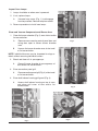
Inspect Oven Lamps
1. Lamps should be on when oven is powered.
2. If not, replace lamps.
A.
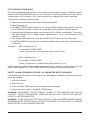
Unscrew lamp cover (Fig. 1) to disengage
from lamp sockets. Remove lamp from socket.
3. Reverse procedure to install new lamps.
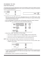
Clean and Vacuum Components and Burner Area
1. Clean the burner chamber (Fig. 2) area of dust and/or
lint accumulation.
A.
Remove screw securing control panel door and
swing door open to access burner chamber
area.
B.
Vacuum the burner chamber area of dust and/
or lint accumulation.
Fig. 1
NOTE: Individual burners may be inspected for clogs or
debris without removing individual burners.
2. Check and clean all air passageways.
A.
Clean all burner chamber air passageways of
dust and/or lint accumulation.
3. Clean convection panel grill.
A.
Clean convection panel grill (Fig. 3) of dust and/
or lint accumulation.
4. Clean draft inducer housing grill guard (Fig. 4).
A.
Access draft inducer housing on top of oven
and clean grill cover of dust and/or lint
accumulation.
Fig. 2
Fig. 4
Fig. 3
– 29 –
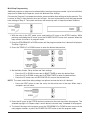
Inspect Rack Rotation Assemblies
NOTE: Before performing rack inspection, observe condition of rack rotation belt.
1. Check rack rotation belt.
A.
Gain access to the top of oven and loosen the screws securing rack rotation assembly
cover (Fig. 5).
B.
Lift cover from top of oven.
C.
Observe condition of the rack rotation belt. If belt is worn or damaged, contact your local
Hobart Bakery Systems service office.
D.
Reverse procedure to install.
2. Check rack assembly for proper operation.
A.
Put oven into operation with customer’s typical bake product load weight on rack. If rack
does not stop in the proper rack load/unload position, contact your local Hobart Bakery
Systems service office.
NOTE: Some under or over travel of rack positioning should be expected depending on product load.
Inspect Door Components
1. Check and or adjust door gaskets.
A.
While operating oven, if air (or steam)
blows out from the top, sides or
underneath the doors, door gasket will
need to be adjusted or replaced.
B.
If gasket needs replaced, contact your
local Hobart Bakery Systems service
office.
2. Check door switch operation.
Fig. 5
A.
Turn oven on and set a normal bake
temperature.
B.
With the oven doors closed, press
START button and observe rack rotation.
If no rotation, contact your local Hobart
Bakery Systems service office.
Inspect Air Louvers
1. Check air louvers (shutters) (Fig. 6) inside
oven and tighten any loose screws.
2. Check oven interior, and tighten or replace
loose or missing panel screws.
Fig. 6
– 30 –
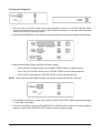
Inspect Cavity Vent
1. Check cavity vent for proper operation.
A.
Push VENT button (Fig. 7) on control panel to open vent and push again to close vent.
B.
Visually check that vent opens (Fig. 8) and closes (Fig. 9) when button is pushed. If vent
does not operate, contact your local Hobart Bakery Systems service office.
Fig. 7
Fig. 8
Fig. 9
Visually Inspect Electrical Connections
1. Remove screw securing control panel door and swing door open to access burner compartment
area.
2. Inspect all wiring connections for discoloration. If discoloration is visible, contact your local
Hobart Bakery Systems service office.
– 31 –
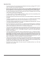
Verify Ignition Module Safety Lockout Functions
1. Verify ignition module safety lockout functions.
A.
Turn the oven on and close the doors.
B.
Turn off gas supply to oven.
C.
Set the oven control to call for heat, make sure convection fan is running.
D.
Remove screw securing control panel door and swing door open to access burner
compartment area.
E.
Observe LED on ignition module. After trying to light the burner, the module should lockout
(See following chart.)
F.
Turn gas supply back on to oven.
G.
Set the oven control to call for heat and make sure convection fan is running and the burner
has established a flame.
H.
Turn the gas supply off to the oven.
I.
Observe LED on ignition module (Fig. 10). The module should go into lockout. (See
following chart.)
Fig. 10
J.
If the results have been obtained, proceed to next preventive maintenance procedure.
K.
If the results have not been obtained, contact your local Hobart Bakery Systems service
office.
– 32 –
2. Verify operation of draft inducer pressure switch.
A.
Turn incoming power off to oven.
B.
Remove screw securing control panel door and swing door open to access burner
compartment area.
C.
Loosen hose clamp (Fig. 11) and remove vacuum tube from the vacuum switch.
NOTE: Some ovens may have rectangular-shaped vacuum switches.
D.
Reconnect incoming power to oven and turn oven on.
E.
Set oven to heat and press START.
F.
The burners should not come on at this time.
G.
If the burners do not come on, proceed to next preventive maintenance procedure.
H.
If the burners do come on, contact your local Hobart Bakery Systems service office.
I.
Reverse the procedure to install.
Fig. 11
NOTE: Use normally open, common terminals and low vacuum port for the vacuum switch setup.
3. Verify operation of draft inducer (stack fan) pressure switch.
A.
Set oven for heat.
B.
Disconnect tubing from exhaust vent collar. Burner should go out.
C.
Reconnect tubing and burner should establish a flame.
D.
If the results have been obtained, proceed to next preventive maintenance procedure.
E.
If the results have not been obtained, contact your local Hobart Bakery Systems service
office.
– 33 –
Verify Operation of Steam
1. Check steam system for proper operation.
A.
Turn the water supply on.
B.
Turn the oven on and set to normal bake temperature.
C.
Allow to cycle three times to stabilize temperature.
D.
Set control to call for steam.
E.
Observe operation. If steam is not observed, contact your local Hobart Bakery Systems
service office.
After completion of the Owner PM Procedures, you will need to contact a qualified servicer for
any needed repairs.
Keep a copy of the Owner Preventive Maintenance Checklist for your records.
– 34 –
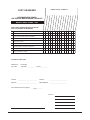
MODEL/SERIAL NUMBERS
COPY AS NEEDED
RECOMMENDED OWNER
PREVENTIVE MAINTENANCE CHECKLIST
BAKERY RACK OVENS - GAS
CHECK FOR PROPER OPERATION OR CLEAN.
CALL FOR SERVICE AS NECESSARY
Inspect oven lamps
Clean and vacuum components and burner areas
Inspect rack lift and rotation assemblies
Inspect door components
Inspect air louvers
Inspect cavity vent
Visually inspect electrical connections
Verify ignition module safety lockout functions
Verify operation of steam
√ = PROCESS COMPLETED
PM Frequency:
Type of Gas
Location:
Bi-monthly
Natural Gas _____________
Propane_____________
________________________________
Inspector: ________________________________
Store No.
_____________________________
Date Completed: _____________________________
Service Notified for Necessary Repairs: _____________________
(Date)
Comments:
(Inspector Signature)
– 35 –
FORM 36705 (Oct. 2005)
– 36 –
PRINTED IN U.S.A.