1
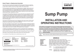
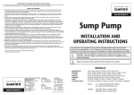
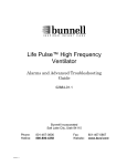
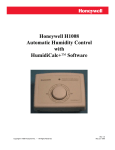
GAS RACK OVENS
WITH ELECTRONIC OVEN CONTROL
MODELS
DRO2G
GAS
DRO2GH
GAS
701 S. RIDGE AVENUE
TROY, OHIO 45374-0001
937-332-3000
www.hobartcorp.com
FORM 19202 Rev. D (Dec. 2003)
IMPORTANT FOR YOUR SAFETY
THIS MANUAL HAS BEEN PREPARED FOR PERSONNEL QUALIFIED TO INSTALL GAS
EQUIPMENT, WHO SHOULD PERFORM THE INITIAL FIELD START-UP AND
ADJUSTMENTS OF THE EQUIPMENT COVERED BY THIS MANUAL.
POST IN A PROMINENT LOCATION THE INSTRUCTIONS TO BE FOLLOWED IN THE
EVENT THE SMELL OF GAS IS DETECTED. THIS INFORMATION CAN BE OBTAINED
FROM THE LOCAL GAS SUPPLIER.
IMPORTANT
IN THE EVENT A GAS ODOR IS DETECTED, SHUT
DOWN UNITS AT MAIN SHUT-OFF VALVE AND
CONTACT THE LOCAL GAS COMPANY OR GAS
SUPPLIER FOR SERVICE.
FOR YOUR SAFETY
DO NOT STORE OR USE GASOLINE OR OTHER
FLAMMABLE VAPORS OR LIQUIDS IN THE
VICINITY OF THIS OR ANY OTHER APPLIANCE.
WARNING
IMPROPER INSTALLATION, ADJUSTMENT,
ALTERATION, SERVICE OR MAINTENANCE CAN
CAUSE PROPERTY DAMAGE, INJURY OR DEATH.
READ THE INSTALLATION, OPERATING AND
MAINTENANCE INSTRUCTIONS THOROUGHLY
BEFORE INSTALLING OR SERVICING THIS
EQUIPMENT.
IN THE EVENT OF A POWER FAILURE, DO NOT
ATTEMPT TO OPERATE THIS DEVICE.
KEEP AREA AROUND OVEN CLEAR OF
COMBUSTIBLES.
DO
NOT
OBSTRUCT
COMBUSTION AND VENTILATION OPENINGS ON
THE OVEN.
© HOBART CORPORATION, 2001
–2–
Table of Contents
GENERAL ............................................................................................................................................... 4
INSTALLATION ........................................................................................................................................ 4
OPERATION ............................................................................................................................................ 5
Before First use ............................................................................................................................ 5
Loading and Unloading ................................................................................................................. 6
Door Handle ................................................................................................................................. 7
Controls (Fig. 3) ............................................................................................................................ 7
Oven preheat .............................................................................................................................. 10
Program baking .......................................................................................................................... 10
Manual Baking ............................................................................................................................ 12
Control panel updates ................................................................................................................ 13
Oven vent Controls .................................................................................................................... 14
Oven Preset Values ................................................................................................................... 14
Cleaning ..................................................................................................................................... 14
MAINTENANCE .................................................................................................................................... 15
General .......................................................................................................................................
Lubrication ..................................................................................................................................
Service and Parts Information ....................................................................................................
Preventive Maintenance .............................................................................................................
15
16
16
16
OWNER PREVENTIVE MAINTENANCE PROCEDURE .................................................................... 17
Introduction ................................................................................................................................. 17
Preventive Maintenance Procedures ......................................................................................... 17
–3–
OPERATION and CARE of
MODELS DRO2G & DRO2GH GAS
RACK OVENS WITH ELECTRONIC OVEN CONTROL
PLEASE KEEP THIS MANUAL FOR FUTURE USE
GENERAL
Models DRO2G and DRO2GH Gas ovens accommodate roll-in racks. They are equipped with an
electronic oven control for baking and/or steaming applications. A mechanism in the ceiling rotates the
rack during baking.
Model DRO2G is rated at 318,000 BTU and model DRO2GH is rated at 375,000 BTU (natural or
propane gas).
Hobart Rack Ovens are produced with quality workmanship and material. Proper installation, usage
and maintenance of your Rack Oven will result in many years of satisfactory performance.
It is suggested that you thoroughly read this manual and carefully follow the instructions provided.
INSTALLATION
Models DRO2G and DRO2GH must only be installed or moved by Hobart-trained service technicians.
–4–
OPERATION
WARNING: THE RACK OVEN AND ITS PARTS ARE HOT. USE CARE WHEN OPERATING,
SERVICING OR CLEANING THE OVEN.
BEFORE FIRST USE
Before using the oven for the first time, it must be burned in to release any odors that might result from
heating the new surfaces in the oven.
WARNING: DISCONNECT ELECTRICAL POWER TO THE MACHINE AND FOLLOW
LOCKOUT / TAGOUT PROCEDURES.
1. Using a clean cloth moistened in warm, soapy water, wash the stainless steel interior of the oven.
2. Rinse with clean water and dry with a clean, dry cloth.
3. Start up:
1. Set the shutoff gas valve and burner gas valve to ON.
2. Turn on electrical supply.
3. Turn the power switch to the ON position.
4. Set desired temperature.
5. Confirm that loading door is closed.
6. Wait for rack oven to reach set temperature.
4. Operate the oven at 350°F (176°C) for 6 to 8 hours.
5. Complete shutdown:
1. Turn off gas supply by setting shutoff gas valve and
burner gas valve to OFF.
2. Turn off electrical supply.
3. Turn the power switch to the OFF position.
4. Before restarting oven, burner gas valve, shutoff gas
valve and power switches must be off for a minimum
of 5 minutes.
–5–
LOADING AND UNLOADING
WARNING: THE OVEN AND ITS PARTS ARE HOT. TO PREVENT BURNS, USE HOT PADS OR
PROTECTIVE MITTS WHEN LOADING OR UNLOADING THE OVEN.
Double Rack
1. Roll the rack into the oven so the End Brackets channel onto the Rack Lifting Device (Fig. 1).
2. Close and latch the door. (See Operation.)
3. When baking is completed, the buzzer will sound. Press TIMER STOP.
4. Wait until the rack stops rotating. Open the door; the rack is lowered to the floor.
Single Rack
1. Roll the first rack into the oven so the Side Brackets channel onto the Rack Lifting Device
(Fig.1). Close the door and press JOG. The rack turns around to the next load-unload position,
then stops.
2. Open the door and roll the second rack into the oven so the Side Brackets channel onto the Rack
Lifting Device (Fig.1).
3. Close and latch the door. (See Operation.)
4. When baking is completed, the buzzer will sound. Press TIMER STOP.
5. Wait until the racks stop rotating. Open the door; the racks are lowered to the floor.
NOTE: On newer models the Rack Lifting Device is equipped with a stop on both ends. Manually flip
the stop open to slide the rack(s) off.
Fig. 1
–6–
DOOR HANDLE
When the door is closed, make sure the door handle is in the fully vertical position (Fig. 2).
Fig. 2
CONTROLS (Fig. 3)
All of the oven’s baking processes are controlled here. Whether you bake in manual baking mode or
program a baking process and recall it from memory, the same parameters must be defined for any
baking operation.
Fig. 3
–7–
OVEN TEMPERATURE - Indicates the current oven temperature in Fahrenheit or Celsius.
HEAT ON - Indicates the heat is on when lit.
SET TEMPERATURE - Displays the set baking temperature.
SET TEMPERATURE UP and DOWN - Press to adjust the temperature to the desired setting. The
temperature cannot be set higher than 550°F (288°C).
BAKE - Press to power up the oven for baking. The BAKE light and all temperature and time displays
come on. Oven comes up to set baking temperature.
OFF - Press to turn the oven systems off. The control display turns off. Rack rotation stops immediately
if running. The stack fan (in the exhaust system) will stay on for 20 minutes after the control is turned
off.
FAN - Press to cool down the oven after use. The fan light and all temperature and time displays come
on. Only the fan is operational. BAKE TIME and STEAM TIME are not operational.
JOG - Press to turn rack(s) around to the next load-unload position. Only operates when the door is
closed. The rack rotation device rotates the rack(s) to the next load-unload position then stops to allow
the operator to open the door.
–8–
BAKE TIME - Displays the baking time in minutes.
BAKE TIME UP and DOWN
arrows - Press to adjust the baking time in minutes.
STEAM TIME - Displays the steam time in seconds.
STEAM TIME UP and DOWN
arrows - Press to adjust the steam time in seconds.
TIMER START - Press to start the timer. The flashing light in the BAKE TIME display indicates the timer
is counting down.
TIMER STOP - Press to stop the timing countdown. The rack rotation will stop at the next load-unload
position.
PROGRAM # - Displays current baking program in use.
PROGRAM # UP
- Press to scroll through the baking programs.
PROGRAM # ENTER - Press to save baking parameters on program numbers 1 through 9.
–9–
OVEN PREHEAT
The oven will need to preheat to the desired baking temperature before baking begins.
1. Press BAKE. The BAKE light and all temperature and time displays come on.
2. The door must be closed to operate the oven fan and heat. The HEAT ON light is lit when the heat
is on.
3. Adjust the SET TEMPERATURE to the desired setting by pressing the corresponding UP or
DOWN
arrow keys. The SET TEMPERATURE cannot be set higher than 550°F (288°C).
4. Adjust BAKE TIME (in minutes) to the desired setting by pressing the corresponding UP or
DOWN
arrow keys.
5. Adjust STEAM TIME (in seconds) to the desired setting by pressing the corresponding UP or
DOWN
arrow keys.
6. If the STEAM TIME is more than the maximum STEAM TIME, which is factory preset at
20 seconds, then the oven provides steam for 20 seconds and pauses for the remaining time.
7. It takes about 20 minutes for the oven to reach operating temperature and preheat the
humidification system.
NOTE: The maximum STEAM TIME is preset at 20 seconds to reduce risk of overhumidification.
However, this value can be adjusted by your service technician.
PROGRAM BAKING
Up to nine programs can be stored in memory and recalled by number when needed. A program is a
set of baking parameters - SET TEMPERATURE, BAKE TIME and STEAM TIME - that the operator
defines for any baking operation.
arrow key to scroll through the program numbers (1 to 9). Program # 0
Use the PROGRAM # UP
is used for manual baking processes that are not assigned to memory (see MANUAL BAKING on page
11).
Create and Save a Program
1. Press the PROGRAM # UP
program (numbers 1 to 9).
arrow key to select the number where you want to store the
2. Set the TEMPERATURE, BAKE TIME and STEAM TIME.
3. Use the appropriate UP and DOWN
arrow keys to adjust the settings.
4. Press and hold ENTER key for 3 seconds until you hear a beep.
5. The program is saved.
– 10 –
Change a Program
1. Press the PROGRAM # UP
arrow key until the desired program number is displayed.
2. The current settings are displayed.
3. Change only the settings that need to be changed.
4. Use the appropriate UP and DOWN
arrow arrow keys to adjust the settings.
5. Press and hold ENTER key for 3 seconds until a beep is heard.
6. Change is complete.
7. If the PROGRAM # UP
arrow key does not change the program number, press OFF and
BAKE to reset and begin again.
Finding and Using a Program
1. Press the PROGRAM # UP arrow key until the desired program number is displayed.
2. Allow the OVEN TEMPERATURE to reach the SET TEMPERATURE.
3. Load the oven and close the oven door.
4. Press TIMER START. The flashing light in the BAKE TIME display indicates the timer is counting
down.
5. When the BAKE TIME display reaches 000, the display flashes and the beeper sounds.
6. Press TIMER STOP to silence the beeper and restore the initial program settings to the displays.
Heat and rack rotation remain on until you press TIMER STOP a second time.
Operational Hints
•
If you press TIMER STOP during a baking cycle, the timer will stop and the rack rotation will stop
at the next load-unload position.
•
When the baking cycle is completed (BAKE TIME reads 000), the display flashes and the beeper
sounds. Press TIMER STOP to silence the beeper and restore the initial bake settings to the
displays. Heat and rack rotation remain on until you press TIMER STOP a second time.
•
The OVEN TEMPERATURE displays the actual oven temperature until it reaches and stays
within 10 degrees of the SET TEMPERATURE. The SET TEMPERATURE will be displayed as
both the OVEN TEMPERATURE and the SET TEMPERATURE.
– 11 –
MANUAL BAKING
Program # 0 is used for manual baking processes that are not assigned to memory.
1. Press the PROGRAM # UP
arrow key to 0. If the PROGRAM # UP arrow key does not change
the program number, press OFF and BAKE to reset and begin again. Program # 0 is factory
preset as follows:
•
SET TEMPERATURE - 350°F (176°C).
•
BAKE TIME - 000 min.
•
STEAM TIME - 00 sec.
2. Set the TEMPERATURE, BAKE TIME and STEAM TIME.
3. Use the appropriate UP and DOWN
arrow keys to adjust the settings.
4. Allow the OVEN TEMPERATURE to reach the SET TEMPERATURE.
5. Load the oven. Press TIMER START to operate.
6. When BAKE TIME display reaches 000, the display flashes and the beeper sounds.
7. See CONTROL PANEL UPDATES for setting more time, if applicable.
8. Press TIMER STOP to silence the beeper and restore the initial settings to the displays. Heat and
rack rotation remain on until you press TIMER STOP a second time.
– 12 –
CONTROL PANEL UPDATES
WARNING: DISCONNECT ELECTRICAL POWER TO THE MACHINE AND FOLLOW
LOCKOUT / TAGOUT PROCEDURES.
The DRO2 series ovens have different software configurations for the control panel depending on the
date of manufacture. This is identified by a Control Version Number.
The Control Version Number is indicated in the serial number, which is printed on a label on the back
of the control panel display box. To access the back of the box, open the electrical panel on the left
side of the oven. The label may read FFA4-9426 or FFB1-9544-0814 or FFB1-9611-XXXX.
On models with Control Version Number 9611 and up, the number will be displayed on the control panel
for 2.5 seconds after you press OFF.
Control Version 9544 and Up
Setting additional cook time in minutes.
1. Reset the BAKE TIME using the UP and DOWN
arrow keys.
2. If the STEAM TIME is programmed, set the STEAM TIME to 00.
3. Press TIMER START. Do not press ENTER as this will change the program settings.
Control Version 9611 and Up
This version is fitted with a volume control adjustment for the timer beeper. The volume control is
located on the back, bottom right corner of the control panel display box. To access the back of the box,
open the electrical panel on the left side of the oven.
Setting additional cook time in minutes and seconds (5-second increments).
1. Press TIMER STOP.
2. Timer displays 0.00 minutes and seconds. Use the UP and DOWN arrow keys to adjust the time.
Press TIMER START to begin countdown.
3. When timer display reaches 0.00, the display flashes and the beeper sounds. Press TIMER
STOP.
4. Set more time by repeating this procedure. When the product is done, unload the oven and press
TIMER STOP again to revert back to the original program.
Models Built After June 2001
When the oven heat is first turned on, the control goes through a short monitoring sequence to make
sure the burner is operating correctly. The HEAT ON has a tricolor LED to indicate status.
Yellow The control is monitoring the purging cycle.
Green
The burner is on and the heat is on; heating is OK.
Red
Indicates a burner malfunction during the monitoring sequence. The display will flash and
a buzzer will sound, indicating that the monitoring sequence has stopped. To reset the
control after a burner malfunction, turn the control panel off then back on.
– 13 –
OVEN VENT CONTROLS
When changing to a product which requires a lower baking temperature, the oven can be cooled down
by exhausting heat from the oven using the Vent. To cool down the oven, open the Damper by pulling
the knob outward (Fig. 4).
Fig. 4
OVEN PRESET VALUES
•
The maximum SET TEMPERATURE is 550°F (288°C).
•
The SET TEMPERATURE for PREHEAT # 0 is 350°F (176°C).
•
The maximum STEAM TIME is preset at 20 seconds.
•
The control readout can be changed from Fahrenheit to Celsius.
CLEANING
WARNING: THE RACK OVEN AND ITS PARTS ARE HOT. USE CARE WHEN OPERATING,
SERVICING OR CLEANING THE RACK OVEN.
WARNING: DISCONNECT ELECTRICAL POWER TO THE MACHINE AND FOLLOW
LOCKOUT / TAGOUT PROCEDURES.
1. Allow the oven to cool.
2. Clean the outside of the oven daily with a clean, moistened cloth.
3. Remove rack(s) and clean as you would any cooking utensil. Use warm, soapy water and a
brush. Rinse with clear water, and dry with a clean cloth.
4. Use care when cleaning around sensitive interior parts such as probes, sensors or the rotating
mechanism.
5. Using a clean cloth moistened in warm, soapy water, wash the stainless steel interior of the oven,
rinse with clear water and dry with a clean cloth.
6. Gently scrape heavy buildup off door glass. Residue can be removed with a glass cleaner when
oven is cool.
7. Do not use oven cleaners or steel wool on stainless steel surfaces. Never spray down the oven
with water or steam.
– 14 –
MAINTENANCE
WARNING: THE RACK OVEN AND ITS PARTS ARE HOT. USE CARE WHEN OPERATING,
SERVICING, OR CLEANING THE OVEN.
WARNING: DISCONNECT ELECTRICAL POWER TO THE MACHINE AND FOLLOW
LOCKOUT / TAGOUT PROCEDURES.
GENERAL
As Needed
• Inspect the area around the oven. The area must be free and clear from combustibles. There must
be no obstructions to the air flow.
Daily
• Clean exterior.
Weekly
• Clean the oven interior and remove lose debris (see Cleaning section).
• Clean the windows.
• Empty grease catcher if equipped.
Bi-Monthly
• Owner Preventive Maintenance
Monthly
• Clean exhaust hood filters (if equipped) with soap and water.
Annually
•
Preventive Maintenance.
– 15 –
LUBRICATION
None required.
SERVICE AND PARTS INFORMATION
Contact your local authorized Hobart office for service .
PREVENTIVE MAINTENANCE
The DRO2 oven should be kept on a regular preventive maintenance schedule. Ovens require specific
preventive maintenance based on usage and environmental factors. The failure to have the oven
properly maintained by following recommended preventive maintenance procedures may result in
higher repair costs, shortened equipment life or unsafe operating conditions.
The performance of routine preventive maintenance on any rack oven, which is the owner’s
responsibility, will help to ensure continued safe and reliable operation.
A preventive maintenance program is your best option for continued safe and reliable oven operation.
We believe that Hobart Service is your best choice for performing preventive maintenance.
– 16 –
OWNER PREVENTIVE MAINTENANCE PROCEDURE
INTRODUCTION
This owner preventive maintenance (PM) section includes procedures to inspect for proper operation
and cleaning of components. Owner Preventive Maintenance Procedures are written for gas ovens.
They can also be used for electric ovens by omitting the steps that refer to components found only on
gas ovens. Customer PMs should be conducted bi-monthly per OSHA Bakery Oven Inspection
Standard 29 CFR 1910.263(l)(9)(ii). A convenient PM Checklist is provided at the end of this section.
NOTE: This PM procedure does not discuss repair or replacement of components. Upon completion
of the PM procedure you will need to contact a qualified servicer for any needed repairs.
Tools Used for Inspection Procedure
• Standard set of hand tools
• Vacuum Cleaner - Shop Vac
PREVENTIVE MAINTENANCE PROCEDURES
WARNING: DISCONNECT THE ELECTRICAL POWER TO THE MACHINE AND FOLLOW
LOCKOUT / TAGOUT PROCEDURES.
WARNING: SHUT OFF THE GAS BEFORE SERVICING THE UNIT.
WARNING: CERTAIN PROCEDURES IN THIS SECTION REQUIRE ELECTRICAL TEST OR
MEASUREMENTS WHILE POWER IS APPLIED TO THE MACHINE. EXERCISE EXTREME
CAUTION AT ALL TIMES. IF TEST POINTS ARE NOT EASILY ACCESSIBLE, DISCONNECT
POWER AND FOLLOW LOCKOUT / TAGOUT PROCEDURES, ATTACH TEST EQUIPMENT AND
REAPPLY POWER TO TEST.
Inspect Oven Lamps
1. Lamps should be on when oven is powered.
2. If not, replace lamps.
A.
Remove screws (Fig. 5) securing
oven lamp housing to the oven.
B.
Pull lamp housing away from oven.
C
Remove oven lamps by turning lamps
out of lamp socket.
D.
Reverse the procedure to install new
lamps.
Fig. 5
– 17 –
Clean and Vacuum Components and Burner Areas
1. Clean the burner compartment (Fig. 6) area of dust and/or lint accumulation.
2. Vacuum the burner compartment (Fig. 6) floor of dust and/or lint accumulation.
3. Check and clean all air passageways (Figs. 7 & 8).
A.
Clear objects blocking all burner compartment air passageways.
B.
Clean all burner compartment air passageways of dust and/or lint accumulation.
Fig. 7
Fig. 6
Fig. 8
Inspect Rack Lift and Rotation Assemblies
1. Check rack lift assembly for proper operation.
A.
Open door. Rack lift should lower to correct height and be in forward loading position to
accept rack entry. If not, contact your local authorized Hobart office for service.
2. Check all V-belts.
A.
Gain access to the top of oven and check all V-belts for wear or damage. If belts are worn
or damaged, contact your local authorized Hobart office for service.
3. Tighten all bolts on “A” type racks.
A.
Check and tighten all bolts on lift rack.
– 18 –
Inspect Door Components
1. Verify door switch operation (Fig. 9).
A.
Open door.
B.
While watching the door switch (at top of oven), close the door.
C.
The door switch should be operated.
D.
With the door open, the switch should be un-operated.
2. Check loading door latch bushings.
A.
Open door.
B.
Inspect door latch bushings for wear. If the bushings are worn, contact your local
authorized Hobart office for service.
C.
With the door closed, the gasket should provide an even seal and not let hot air or steam
escape from around the door.
3. Check door sweep.
A.
The door sweep should contact the ramp approximately 1/8" evenly across door width,
when door is in the closed position.
B.
If door sweep needs replaced or adjusted, contact your local authorized Hobart office for
service.
Inspect Air Louvers
1. Check air louvers (Fig. 10) (shutters) inside oven and tighten any loose screws.
2. Check oven interior, tighten or replace loose or missing panel screws.
Fig. 9
Fig. 10
– 19 –
Inspect Cavity Vent
1. Check vent for proper operation.
A.
Pull vent handle (Fig. 11) out to open vent
and push handle back in to close vent.
B.
Visually check that vent opens and closes
when handle is moved. If vent does not
open or close, contact your local
authorized Hobart office for service.
Visually Inspect Electrical Connections
1. Inspect all wiring connections for discoloration. If
discoloration visible, contact your local authorized
Hobart office for service.
Verify Ignition Module Safety Lockout Functions
Fig. 11
1. Start up attempt with main gas valve off.
A.
Turn main gas valve off.
B.
Close the door and turn the oven on and set control panel to call for heat.
C.
Be sure convection fan is running.
D.
The ignition module should start a 30 second purge cycle. Once this is accomplished, the
gas valve and ignition transformer are simultaneously energized for 4 seconds for ignition
trial to establish the main burner flame.
E.
If no burner flame is establish during the 4 second trial for ignition, the ignition module should
go into lockout and not attempt to reignite the burner. Monitor the oven for 40 seconds and
verify that the module does not re-attempt ignition. If module does re-attempt ignition,
contact your local authorized Hobart office for service.
2. Lost flame while burner is firing.
A.
Turn the main gas valve on and turn the oven off and back on to reset the oven.
B.
Close the door and set the control panel to call for heat, be sure the convection fan is
running.
C.
Turn the main gas valve off, the burner flame should go out.
D.
The ignition module should attempt one trial for re-ignition by starting a 30 second purge
cycle. Once this is accomplished, the gas valve and ignition transformer are simultaneously
energized for 4 seconds for ignition trial to establish the main burner flame.
E.
If no burner flame is established during the 4 second trial for ignition, the control should go
into lockout and not attempt to reignite the burner. Monitor the oven for 40 seconds and
verify that the module does not re-attempt ignition. If module does re-attempt ignition contact
your local authorized Hobart office for service.
– 20 –
Verify Ignition Module Safety Lockout Functions - cont.
3. Reset control after safety lockout.
A.
With the control in a lockout condition, turn the main gas valve on.
B.
Reset the control by turning the oven control off and then back on.
C.
Ignition module should perform the 30 second purge and then burner should establish a
flame. If flame is not established, contact your local Hobart office for service.
D.
If the ignition module fails this test, contact your local Hobart office for service.
4. Verify operation of combustion blower pressure switch (Fig. 12).
A.
Turn the oven on and close the door.
B.
Set the oven control to call for heat, make sure convection fan is running and the burner
has established a flame.
C.
With the burner flame established, pull the pressure hose off the pressure switch
hose barb (Fig. 12).
D.
The burner flame should extinguish but the burner blower should continue to operate. If not,
contact your local authorized Hobart office for service.
E.
Reconnect the pressure hose to the pressure switch, ignition module should start a 30
second purge cycle and re-establish a flame.
F.
If the correct results have been obtained, proceed to step 5.
G.
If the correct results have not been obtained pressure switch malfunctioned, contact your
local Hobart office for service.
5. Verify operation of draft inducer (stack fan) pressure switch.
A.
Turn the oven on and set the temperature to call for heat and burner flame established.
NOTE: If burner flame does not establish, check pressure switch tubing for loose connections or kinks.
Correct tubing before proceeding.
B.
De-energize draft inducer (stack fan) by switching off CB2 breaker (Fig. 13).
NOTE: Depending on the age of the control package, draft inducer breaker CB2 may be different than
specified. If CB2 is not on the oven, contact your local authorized Hobart Service office.
Fig. 13
Fig. 12
– 21 –
Verify Ignition Module Safety Lockout Functions - cont.
C.
Verify that draft inducer motor stops running.
D.
Verify contactor 4 CON de-energized (Fig. 14).
E.
Verify burner shuts down.
F.
If burner shuts down, proceed to step H.
G.
If burner did not shut down, the draft inducer (stack fan) pressure switch malfunctioned;
contact your local authorized Hobart office for service.
H.
Energize draft inducer (stack fan) by switching on CB2 breaker (Fig. 13).
I.
Verify that draft inducer (stack fan) motor starts running.
J.
Verify contactor 4 CON energized (Fig. 14).
K.
Verify that controller is calling for heat.
L.
Verify that burner is operating after 30 second purge cycle.
M.
If the burner is operating, proceed to step 6.
N.
If the burner is not operating, the draft inducer (stack fan) pressure switch malfunctioned;
contact your local authorized Hobart office for service.
Fig. 14
– 22 –
Verify Ignition Module Safety Lockout Functions - cont.
6. Verify draft inducer motor operation.
A.
Turn the oven on.
B.
Visually inspect the convection motor for vibration while motor is running.
C.
If vibration is present, motor operation did not pass test; contact your local authorized
Hobart office for service.
D.
If vibration is not present, motor operation passed.
Verify Operation of Steam System
1. Check steam system for proper operation.
A.
Turn oven on and set to normal bake temperature.
B.
Turn water supply on.
C.
Allow system to cycle three times to stabilize temperature.
D.
Set oven to call for steam.
E.
Observe operation. If steam is not observed, contact your local authorized Hobart office for
service.
After completion of the owner PM procedure, you will need to contact a qualified servicer for
any needed repairs.
Keep a copy of the Owner Preventive Maintenance Checklist for your records.
– 23 –
MODEL/SERIAL NUMBERS
COPY AS NEEDED
RECOMMENDED OWNER
PREVENTIVE MAINTENANCE CHECKLIST
BAKERY RACK OVENS - GAS
CHECK FOR PROPER OPERATION OR CLEAN.
CALL FOR SERVICE AS NECESSARY
Inspect oven lamps
Clean and vacuum components and burner areas
Inspect rack lift and rotation assemblies
Inspect door components
Inspect air louvers
Inspect cavity vent
Visually inspect electrical connections
Verify ignition module safety lockout functions
Verify operation of steam
√ = PROCESS COMPLETED
PM Frequency:
Type of Gas
Location:
Bi-monthly
Natural Gas _____________
Propane_____________
________________________________
Inspector: ________________________________
Store No.
_____________________________
Date Completed: _____________________________
Service Notified for Necessary Repairs: _____________________
(Date)
Comments:
(Inspector Signature)
FORM 19202 Rev. D (Dec. 2003)
– 24 –
PRINTED IN U.S.A.