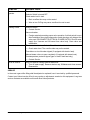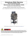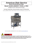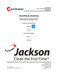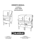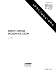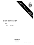
1
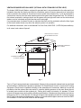
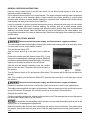
UW50 UTENSIL WASHER
MODEL
UW50
ML-27838
701 S. RIDGE AVENUE
TROY, OHIO 45374-0001
937 332-3000
www.hobartcorp.com
FORM 18241 Rev. G (Aug. 2007)
TABLE OF CONTENTS
GENERAL ..............................................................................................................................................................3
INSTALLATION ......................................................................................................................................................3
Unpacking ........................................................................................................................................................3
Installation Codes ............................................................................................................................................3
Location ...........................................................................................................................................................3
Installation Diagrams .......................................................................................................................................4
Plumbing Connections .....................................................................................................................................7
Gas Connection (When Specified)...................................................................................................................7
Steam Connection (When Specified) ...............................................................................................................7
Venting Required With Gas Heat (Optional With Steam or Electric Heat) .......................................................8
Rate Of Exhaust Flow Calculations .................................................................................................................9
Detergent Feeder (Optional By Others) .........................................................................................................10
Rinse Agent Feeder (Optional By Others) .....................................................................................................10
Vent Exit .........................................................................................................................................................10
Vent Fan Control (Optional); Power Vent (Optional) ......................................................................................10
Electrical Connection .....................................................................................................................................10
OPERATION......................................................................................................................................................... 11
Controls (Fig. 3) ............................................................................................................................................. 11
General Operating Instructions ......................................................................................................................12
Cleaning the Utensil Washer..........................................................................................................................12
Dos and Don'ts For Your New Hobart Utensil Washer ...................................................................................13
MAINTENANCE ...................................................................................................................................................14
Motor ..............................................................................................................................................................14
Wash and Rinse Arms....................................................................................................................................14
Deliming .........................................................................................................................................................14
TROUBLESHOOTING .........................................................................................................................................15
Service ...........................................................................................................................................................16
Model UW50 Utensil
Washer With Booster
©HOBART, 2007
–2–
INSTALLATION, OPERATION AND CARE OF
MODEL UW50 UTENSIL WASHER
SAVE THESE INSTRUCTIONS
GENERAL
The UW50 Utensil Washer is the answer to volume utensil washing problems in your kitchen, bakery or
supermarket operation. The UW50 occupies a minimum amount of floor space (under 48" x 43" with door
open) and does not require separate dishtables. The upper portion of the door raises, while the lower portion
swings out to provide a drain platform. The rack can then be pulled out for easy loading and unloading.
The program selector lets you select a 2-, 4- or 6-minute cycle; each wash cycle is followed by a dwell
and a 24-second rinse. The two upper and two lower wash arms provide thorough cleaning. Four rinse
arms provide a sanitizing rinse at the end of each cycle. The 5-horsepower pump produces 343 gallons
per minute.
The UW50 may be ordered with steam injector, steam coil, electric or gas tank heat. A top-mounted electric
booster is also available. When equipped with a top-mounted electric booster, a spray hose and nozzle
is provided on the left side of the machine. On models without top-mounted electric boosters, the spray
hose and nozzle can be installed in the field as an accessory. Machines equipped with booster heaters
are provided with a pressure-regulating valve and a relief bypass which must be installed in the water
supply line. Machines without booster heaters must have a pressure-regulating valve with relief bypass
(by others) if the incoming line pressure exceeds 25 psig.
Features include: sloping strainer system, self-closing drain with overflow, timed fill, wash and rinse
thermometers and rack with inserts for trays. The flat rack can accommodate a 140-quart Hobart mixer
bowl.
INSTALLATION
UNPACKING
Immediately after unpacking the UW50, check for possible shipping damage. If the UW50 is found to be
damaged, save the packaging material and contact the carrier within 15 days of delivery.
If the Utensil Washer is lifted with a lift truck, place the forks so the drain assembly under the tank is not
damaged.
Prior to installation, test the electrical service to ensure that it agrees with the specifications on the data
plate located below the controls (lower right front).
INSTALLATION CODES
Installation must be in accordance with state and local codes, with the national Fuel Code, ANSIZ223.1
(latest edition), if applicable, and the National Electrical Code ANSI/NFPA70 (latest edition). In Canada,
the installation codes are: CAN/CGA B149.1, CAN/CGA B149.2 and CSA 22.1 (latest edition).
LOCATION
Set the machine in place after the final floor covering is installed. Make sure the machine is level before
making any plumbing connections. Machines equipped with gas heat require a minimum 3" clearance
from the rear of the flue to any combustible construction. Allow at least 3" at the rear and 18" at the sides
of the machine as a suggested minimum for service access. Allow 13" in front of the machine for the door
to lower and sufficient additional space for the operator to work.
–3–
–4–
UW50 with 10KW Electric Tank Heat with or without 14KW Electric Booster – Installation Diagram: D-812969 sheet 1
–5–
UW50 with Steam Tank Heat (Injector or Coil) with or without 14KW Electric Booster – Installation Diagram: D-812969 sheet 2
–6–
UW50 with Gas Tank Heat with or without 14KW Electric Booster – Installation Diagram: D-812969 sheet 3
PLUMBING CONNECTIONS
Plumbing connections must comply with applicable sanitary, safety and plumbing
codes.
Water Supply Connection
Water must be proper hardness. Recommended water hardness is 1 grain or less. Higher hardness may
cause excessive formation of lime scale. Chlorides must not exceed 50 ppm.
A water hammer arrestor (meeting ASSE-1010 Standard) should be provided (by others) in the water
supply line ahead of its connection to the line strainer. The water supply line should be a 3/4" pipe.
A flowing pressure of 15 to 25 psig is required at the pressure gauge, provided. The pressure gauge may
be connected to a petcock, if equipped, and should remain closed, except when the flowing pressure
is being checked. If the flowing pressure exceeds 25 psig, a pressure-reducing valve (not supplied on
machines without booster) must be installed in the water supply line. A pressure-reducing valve with relief
bypass is furnished with machines equipped with a 14KW electric booster.
The water-pressure regulator must have a relief bypass. Failure to use the proper type of
pressure regulator may result in damage to the unit.
The minimum water supply
temperature per cycle time
required to maintain 180°F final
rinse temperature is shown at
the right:
Cycle
Minimum Water Supply Temperatures
With Optional Booster Heater
Without Booster Heater
2 Minute
140°F
180°F
4 Minute
110°F
180°F
6 Minute
80°F
180°F
Drain Connection
A proper drain should be connected to the 2" internal threads at the "T" fitting underneath the machine.
The drain can be connected on either the left or right side of the "T" fitting. The right side of the "T" fitting
is plugged at the factory, allowing the drain to be connected on the left side. If it is more convenient to
connect the drain on the right side, remove the plug from the right side of the "T" fitting, reinstall it on the
left side and connect the drain to the right side.
GAS CONNECTION (WHEN SPECIFIED)
Check the gas data plate attached to the dishwasher or tag attached to the gas burner tubing for type of
gas to be used.
Connect the gas supply to the machine.
The burner is not adjustable. If line pressure is above 7" W.C. (natural gas) or 11" W.C. (propane gas), an
additional regulator valve (not supplied) must be installed in the supply line.
The burner is ignited by solid state electronic circuitry; there is no pilot light. Gas flow is regulated by the
temperature control circuit via a blower and centrifugal switch system.
STEAM CONNECTION (WHEN SPECIFIED)
Machines equipped with steam injector tank heat have a steam connection (3/4" female pipe thread) located
under the machine at the rear, 6" above the floor. Machines equipped with steam coil tank heat have the
steam supply connection (3/4" female pipe thread) located at the rear of the wash tank, 19" above the floor,
and a condensate return connection (3/4" female pipe thread), located at the rear of the wash tank, 123/8"
above the floor (a bucket-type trap is furnished). For either type of steam heat, flowing steam pressure
should be 15 to 25 psig (50 psig maximum). A manually operated steam control valve (supplied by others)
should be installed at a convenient location ahead of the steam supply connection.
–7–
VENTING REQUIRED WITH GAS HEAT (OPTIONAL WITH STEAM OR ELECTRIC HEAT)
The Hobart UW50 Utensil Washer, equipped for gas tank heat, is not provided with a flue collar and is not
intended to have the flue directly connected to a ventilation system. However, the products of combustion
must be vented to the outside air. A vent hood over the entire utensil washer (Fig. 1) can be employed to
vent both the moist air from the wash chamber and the flue gases from the gas tank heat. The volume of
flue exhaust required for venting moist air and flue gases using a single vent hood over the entire utensil
washer must be calculated using the formulas on the next page.
If a powered means of exhaust is used, an electrical interlock must be provided to allow the flow of gas
to the utensil washer burner only when the exhaust system is in operation.
For additional information, refer to the National Fuel Gas Code, ANSI Z223.1, NFPA 54 (latest editions).
In all cases, local codes will prevail.
EXHAUST DUCT SHOULD
BE CENTERED IN HOOD
6" MINIMUM OVERHANG
ON ALL SIDES
1' TO 4'
CLEARANCE
18" MINIMUM OVERHANG
AT FRONT OPENING
Fig. 1
Type I or Type II canopy hoods are recommended. A factory-built commercial exhaust hood may be listed
as conforming to Underwriters Laboratory's standard 710, titled Exhaust Hoods for Commercial Cooking
Equipment. Hoods must be installed according to the manufacturer's instructions. Make-up air must be
provided so that the exhaust flow rate results in a positive building pressure in the room where the unit
is located (more outside air than exhaust air). Factory-built hoods not tested to UL standard 710 and
custom-built hoods must comply with the following specifications: Stainless steel should have a minimum
thickness of 0.037 in. (0.94 mm) [No. 20 Gauge] or copper sheet weighing at least 24 ounces per square
foot (7 Kg/m2); the hood must be secured in place by noncombustible supports and must meet the RATE
OF EXHAUST FLOW CALCULATIONS on the next page.
–8–
RATE OF EXHAUST FLOW CALCULATIONS (FIG. 2)
Based on the International Mechanical Code (latest edition).
TH
CLEARANCE
HEIGHT
LENGTH
WID
Fig. 2
Canopy size and location
The inside lower edge of canopy-type Type I and II commercial hoods shall overhang or extend a horizontal
distance of not less than 6 inches (152 mm) beyond the edge of the top horizontal surface of the appliance
on all open sides. The vertical distance between the front lower lip of the hood and such surface shall not
exceed 4 feet (1219 mm).
The RATE of air flow required for a vent hood is a minimum of 100 CFM per linear foot of hood length.
–9–
DETERGENT FEEDER (OPTIONAL BY OTHERS)
If installing a detergent feeder (by others), remove cap to expose 7/8" diameter hole at rear of machine.
RINSE AGENT FEEDER (OPTIONAL BY OTHERS)
If a rinse agent feeder (by others) is being installed, remove the 1/8" NPT pipe plug to access the tapped
hole in the incoming water line below the vacuum breaker on top of the machine.
VENT EXIT
A vent exit (7" x 11" x 10") is provided in the top of the machine to allow for expansion of air. It should not
be directly connected to an external vent.
VENT FAN CONTROL (OPTIONAL); POWER VENT (OPTIONAL)
The Vent Fan Control option (factory- or field-installed) provides switching for a vent fan (by others). The
vent hood comes on when the UW50 is on and goes off when the UW50 is off. This is appropriate for
a hood over a UW50 with gas tank heat. The Vent Fan Control can be rewired by your Hobart service
technician to control the Power Vent option (not available on UW50 with gas tank heat). Power Vent is
used on UW50 with steam or electric tank heat to exhaust moist air from the chamber after the rinse cycle
is finished. Power Vent operates for 45 seconds. Power Vent (field installed only) extends upward 131/8"
above the Vent Exit (227/8" above the top of the wash chamber) and terminates in a round duct connection
for a 101/4" O.D. duct.
ELECTRICAL CONNECTION
Electrical and grounding connection must comply with the applicable portions of
the National Electrical Code and/or other local electrical codes.
Disconnect electrical power supply and follow lockout / tagout procedures.
Connect incoming power to the control box in accordance with the wiring diagram located inside the control
box and the electrical data chart. The front trim rail and the front panel must be removed to access the
control box.
ELECTRICAL DATA
10KW Electric
Heat (Single Point
Connections)
10KW Electric Heat
With 14KW Electric
Booster (Single Point
Connections)
Steam Tank Heat
(Injector or Coil)
(Single Point
Connections)
Steam Tank Heat (Injector
or Coil) With 14KW
Electric Booster (Single
Point Connections)
Gas Tank Heat (Single
Point Connections)
Gas Tank Heat With 14KW
Electric Booster (Single
Point Connections)
Volts/Hz/Ph
Rated
Amps
Circuit Size*
(Amps)
Rated
Amps
Circuit Size*
(Amps)
Rated
Amps
Circuit Size*
(Amps)
Rated
Amps
Circuit Size*
(Amps)
Rated
Amps
Circuit Size*
(Amps)
Rated
Amps
Circuit Size*
(Amps)
208/60/3
50.3
70
89.2
**100
20.3
25
60.3
80
21.4
30
60.3
80
240/60/3
46.2
60
79.9
**100
17.6
25
52.3
70
18.6
25
52.3
70
480/60/3
23.5
30
40.4
50
9.2
15
26.4
35
9.6
15
26.4
35
* Minimum Circuit Size / Maximum Protective Device (Amps) compiled in accordance with the National Electrical Code (NFPA 70), latest edition.
** For supply connection, use wires suitable for at least 90°F or equivalent.
Rotation of Pump Motor
Before using the machine, check the pump motor rotation to be sure it is rotating in the right direction. From
the front of the machine, the motor should rotate counterclockwise. Looking from the rear of the machine,
the correct rotation is clockwise. Inspection is easiest from the right side using a flashlight and mirror to
check the motor fan in front. Be aware that the mirror will reverse the perceived direction.
If the pump motor is rotating in the wrong direction, follow this procedure.
Disconnect electrical power supply and follow lockout / tagout procedures.
Reverse any two of the three incoming line wires (not the ground wire). Reconnect and recheck rotation
of pump motor.
– 10 –
OPERATION
CONTROLS (FIG. 3)
SELECTOR
SWITCH
START
6
4
POWER
2
OFF
CYCLE
FILL
PL-56351
Fig. 3
SELECTOR SWITCH
OFF
Electric power to machine is off. POWER and CYCLE lights are off.
FILL
Timed fill requires about 3 minutes. Be sure Drain Lever (Fig. 4) is closed. Press
the START button to begin a timed fill.
SELECT WASH CYCLE and press START.
2
A 2-minute wash cycle is followed by a 5-second pause and a 24-second rinse.
4
A 4-minute wash cycle is followed by a 5-second pause and a 24-second rinse.
6
A 6-minute wash cycle is followed by a 5-second pause and a 24-second rinse.
START button
Begins a timed fill or starts a wash cycle.
POWER light (green)
Indicates the machine has power, and the Selector Switch is not off.
CYCLE light (white)
Amber light indicates a timed fill or wash cycle is in process.
NOTE: Opening the door during cycles will cause cycle to start over at the beginning.
DRAIN LEVER (Fig. 4)
Drain lever is located inside the wash chamber
(middle front with door open). Lower the lever to
close the drain before beginning a timed fill. Rotate
lever upward to open the drain after turning the
machine off at the end of the day.
DIAL THERMOMETERS (not shown)
Thermometers indicate the Wash Tank Temperature
and the Rinse Temperature. Thermometers are
located on top of the wash chamber and are clearly
visible when the doors are shut. Minimum Wash Tank
Temperature is 150°F. Minimum Rinse Temperature
is 180°F.
– 11 –
Fig. 4
GENERAL OPERATING INSTRUCTIONS
Keep the utensil washer clean to provide best results. Do not allow foreign objects to enter the unit,
especially metallic contaminants.
Do not wash aluminum utensils in the utensil washer. The caustic detergent and high water temperature
will cause aluminum oxide formation (black). Copper utensils may require polishing to remove oxide
formation after exposure to utensil washer cleaning for a period of time. Stainless steel utensils should
clean quickly and easily if the food soil is not baked on.
It may be necessary to scrub or prewash some hard-to-remove substances which may not come clean
in the utensil washer with even a 6-minute washing. For stubborn food soil, a plastic scraper, plastic
abrasive pad, nylon bristle brush or sponge with abrasive surface (Scotch Brite) may be used before
washing in the utensil washer. Never use steel wool on ware to be loaded into the utensil washer. Use
only products formulated to be safe on stainless steel. Rinse items thoroughly after scrubbing to remove
metallic debris.
CLEANING THE UTENSIL WASHER
Disconnect electrical power supply and follow lockout / tagout procedures.
The utensil washer must be thoroughly cleaned at the end of each working shift or at least daily. Never
use steel wool to clean utensil washer surfaces.
Turn the Selector Switch OFF.
Open the doors and lift up on the drain lever to drain the
tank.
Remove the strainer pan and strainer basket (Fig. 5), and
empty into a waste disposer or garbage container. Wash and
rinse strainer pan and strainer basket thoroughly. Do not bang
strainer pan or basket on tables to remove food soil.
After the tank has drained completely, lower the overflow
tube to close the drain. Reconnect the electrical power to
the machine.
Fig. 5
Turn the Selector Switch to FILL and press the Start button. The machine will fill and rinse any debris into
the tank.
After Fill is complete, turn the Selector Switch OFF, open the doors and lift up on the drain lever to drain
the machine.
Disconnect electrical power supply and follow lockout / tagout procedures.
Remove the overflow cover and the overflow tube. Wash and rinse the overflow tube inside and out.
Thoroughly cleanse and flush the interior of the machine. Remove remaining soil with a soft cloth or brush
and a mild cleanser. Rinse again. Do not allow food soil to accumulate in the tank bottom.
Reinstall the overflow tube.
Carefully reinstall the strainer pan, strainer basket and drain cover. The opening at the corner of the strainer
pan allows the capillary tube to go into the tank.
On machines with the capillary tube in the tank, use care when assembling strainer pan so the
capillary tube is not damaged during assembly.
Make sure that the wash and rinse arms rotate freely and are free of any obstructions. If any obstructions
are present, remove the wash and rinse arms. Clean the wash and rinse arms under running water in a
sink.
– 12 –
The wash and rinse arms are easily removed for cleaning.
To remove the upper wash and rinse arm (Fig. 6):
•
Unscrew the hand knob.
•
Remove the upper rinse and wash arms together. Be
careful not to drop these arms.
•
Replace after removing any obstructions by reversing
the removal procedure.
To remove the lower wash and rinse arm (Fig. 7):
•
Lift off the rinse arm.
•
Unscrew the rinse arm bearing pin.
•
Lift off the lower wash arm. (It is not necessary to remove
the spacer located on the lower wash arm shaft.)
•
Remove any obstructions from the wash arms.
•
Replace wash and rinse arms by reversing the removal
procedure.
Fig. 6
Leave the doors open to allow the interior to dry and air out.
Fig. 7
DOS AND DON'TS FOR YOUR NEW HOBART UTENSIL WASHER
DO ensure proper water hardness (1 grain or less). Total Dissolved Solids (TDS) must be 50 ppm or
greater. Chlorides must not exceed 50 ppm.
DO pre-scrap dishes thoroughly.
DO use only detergents recommended by your chemical professional.
DO thoroughly cleanse, rinse and dry (leave door open) the machine at the end of the day.
DO closely follow your chemical professional's prescribed deliming schedule.
DO use only products formulated to be safe on stainless steel.
DO NOT use detergents formulated for residential dishwashers.
DO NOT allow food soil to accumulate on the tank bottom.
DO NOT exceed chemical manufacturer's recommended concentrations for detergent, sanitizer, rinse aid
or lime scale remover.
DO NOT use steel wool to clean ware or warewasher surface.
DO NOT allow foreign objects to enter the unit, especially metallic contaminants.
NOTE: Failure to follow use, care and maintenance instructions may void your Hobart warewasher
warranty.
– 13 –
MAINTENANCE
Disconnect electrical power supply and follow lockout / tagout procedures.
MOTOR
The motor has permanently sealed bearings and requires no lubrication.
WASH AND RINSE ARMS
All wash arms and rinse arms should turn freely and continue turning for a few seconds after being whirled by
hand. To check, DISCONNECT ELECTRICAL POWER SUPPLY, rotate arms and remove any obstructions
causing improper operation. Refer to CLEANING THE UTENSIL WASHER on pages 12 and 13.
If the slanted strainer pan and strainer basket are not properly in place, obstructions (such as food particles
or toothpicks) may clog the wash arm nozzles.
DELIMING
Deliming solution must not come in contact with bleach or rinse solution containing
bleach. Mixing may cause hazardous gas to form. This entire procedure must be followed stepby-step for safe and satisfactory results.
The dishwasher should be delimed on a regular basis as required. How often depends on the mineral
content of the water. Deliming should be done when you can see clear signs of lime deposits (a white
chalky substance) on the inside walls and on the wash and rinse arms.
Inspect the machine interior for lime deposits. If deliming is necessary, a deliming agent (available from
your detergent representative) should be used for best results.
Delime as follows:
1. Lift drain lever and drain tank.
2. Remove rack from machine.
3. Close door.
4. Fill machine.
5. Open door and add deliming agent (carefully follow supplier's instructions).
NOTE: The sump holds 27 gallons of water.
6. Close door and allow machine to complete a 6-minute cycle.
7. Open door and lift drain lever to drain tank.
8. Inspect interior of machine for lime deposits. Repeat Steps 3 through 7 if necessary.
Do not allow deliming agent to remain in the machine longer than recommended by the deliming
agent manufacturer. After deliming, run the machine through two 6-minute cycles with no utensils in order
to rinse and flush machine interior.
– 14 –
TROUBLESHOOTING
SYMPTOM
POSSIBLE CAUSE
Utensils spotted or Overloaded rack.
not clean
Low water level.
Water conditions:
— Incorrect rinse water temperature. Refer to WATER SUPPLY CONNECTION,
page 7.
— Excessive water hardness may indicate that a water softener is needed.
— Incorrect detergent type or concentration for water conditions.
— Incorrect rinse additive for water conditions.
Inadequate rinse.
— Dirty line strainer causing reduced water flow. Turn off water supply. Remove
strainer cap. Withdraw and clean screen. Reassemble.
— Low water pressure (supply line).
— Excessive mineral deposits throughout wash and rinse system. Deliming may
be necessary.
Check water level in tank. The machine won't clean well if there isn't enough water
for the pump to maintain adequate wash pressure.
— Drain overflow tube may not be seated.
— Worn or torn O-Ring may cause overflow tube not to seat.
Loss of water pressure due to pump obstruction.
— DISCONNECT ELECTRIC POWER SUPPLY. Drain tank and check for
obstruction at the strainer, basket and pump intake.
Insufficient detergent dispensing.
— Check supply or detergent supplier.
Excessive mineral deposits throughout wash and rinse system.
— Deliming may be necessary.
— Excessive water hardness may indicate that a water softener is needed.
Utensil washer was not cleaned properly. Refer to CLEANING THE UTENSIL
WASHER, pages 12 and 13.
Wash arm blocked with debris. Refer to WASH AND RINSE ARMS, page 14.
– 15 –
SYMPTOM
Machine won't
operate.
POSSIBLE CAUSE
Fuse blown or circuit breaker tripped.
Selector Switch is turned OFF.
Check water level in tank.
— Drain overflow tube may not be seated.
— Worn or torn O-Ring may cause overflow tube not to seat.
Leaking valves.
Solenoid valves.
— Contact Service.
Vacuum breaker.
No wash tank heat.
— Foreign material preventing proper valve operation. A critical period is soon
after installation when pipe compound or metal shavings may lodge at the
valve seat. DISCONNECT ELECTRICAL POWER SUPPLY. Shut off water
supply line. Unscrew and lift bonnet from valve body. Clean valve and
reassemble.
The low water detector will shut off heat if water level is too low.
— Check water level. The overflow tube may not be seated.
Fuse blown or circuit breaker tripped (if equipped with electric heat).
Manual steam valve not open completely (if equipped with steam heat).
Overtemperature protector tripped (gas or electric tank heat only).
No fill or slow fill.
— Contact Service.
Dirty line strainer causing reduced water flow.
— Turn off water supply. Remove strainer cap. Withdraw and clean screen.
Reassemble.
SERVICE
In the event a gas orifice fitting shall be adjusted or replaced, have it serviced by qualified personnel.
Contact your Hobart service office for any repairs or adjustments needed on this equipment. Long-term
service contracts are available on this and other Hobart products.
FORM 18241 Rev G (Aug. 2007)
– 16 –
PRINTED IN U.S.A.