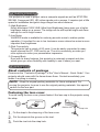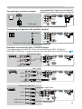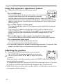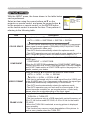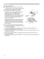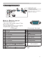
1
Projector CP-S245/CP-X255 User's Manual – Operating Guide Thank you for purchasing this projector. WARNING ►Before using this product, please read the "User's Manual Safety Guide" and related manuals to ensure the proper use of this product. After reading them, store them in a safe place for future reference. About this manual Various symbols are used in this manual. The meanings of these symbols are described below. WARNING This symbol indicates information that, if ignored, could possibly result in personal injury or even death due to incorrect handling. CAUTION This symbol indicates information that, if ignored, could possibly result in personal injury or physical damage due to incorrect handling. Please refer to the pages written following this symbol. NOTE • The information in this manual is subject to change without notice. • The manufacturer assumes no responsibility for any errors that may appear in this manual. • The reproduction, transfer or copy of all or any part of this document is not permitted without express written consent. Trademark acknowledgment • VGA and XGA are registered trademarks of International Business Machines Corporation. • Apple and Mac are registered trademarks of Apple Computer, Inc. • VESA and SVGA are trademarks of Video Electronics Standard Association. • Windows is a registered trademark of Microsoft Corporation. All other trademarks are the properties of their respective owners. 1 Content Content About this manual . . . . . . . . . . 1 Content . . . . . . . . . . . . . . . . . . 2 Projector features . . . . . . . . . . 3 Preparations . . . . . . . . . . . . . . 3 About contents of package . . . . . . . 3 Fastening the lens cover . . . . . . . . . 3 Part names . . . . . . . . . . . . . . . 4 Projector . . . . . . . . . . . . . . . . . . . . . 4 Control buttons . . . . . . . . . . . . . . . . 6 Remote control . . . . . . . . . . . . . . . . 6 Setting up . . . . . . . . . . . . . . . . 7 Arrangement . . . . . . . . . . . . . . . . . . 8 Adjusting the projector's elevator . . 9 Using the Security Bar . . . . . . . . . . 10 Connecting your devices . . . . . . . . .11 Connecting power supply . . . . . . . 14 Remote control . . . . . . . . . . . 15 Putting batteries . . . . . . . . . . . . . . 15 Using the remote control . . . . . . . . 16 Power on/off . . . . . . . . . . . . . 17 Turning on the power. . . . . . . . . . . 17 Turning off the power . . . . . . . . . . . 17 Operating . . . . . . . . . . . . . . . 18 Adjusting the volume . . . . . . . . . . . 18 Temporarily muting the sound . . . . 18 Selecting an input signal . . . . . . . . 18 Searcting an input signal . . . . . . . . 19 Selecting an aspect ratio . . . . . . . . 19 Adjusting the zoom and focus . . . . 19 Using the automatic adjustment feature . 20 Adjusting the position . . . . . . . . . . 20 Correcting the keystone distortions . . 21 Using the magnify feature . . . . . . . 21 Freezing the screen . . . . . . . . . . . . 22 Temporarily blanking the screen . . 22 Operating the computer screen . . . 23 Multifunctional settings . . . . 24 Using the menu function . . . . . . . . 24 2 EASY Menu . . . . . . . . . . . . . . . . . . 25 Aspect, Keystone, Mode, Brightness, Contrast, Color, Tint, Sharpness, Whisper, Mirror, Reset, Filter time, Language, Go to advanced menu PICTURE Menu . . . . . . . . . . . . . . . 27 Brightness, Contrast, Gamma, Color temp, Color, Tint, Sharpness, Progressive, My memory IMAGE Menu . . . . . . . . . . . . . . . . . 30 Aspect, Over scan, V. position, H. position, H. phase, H. size, Auto adjust execute INPUT Menu . . . . . . . . . . . . . . . . . 32 Color space, Component, Video format, Frame lock, Information SETUP Menu. . . . . . . . . . . . . . . . . 34 Keystone, Whisper, Mirror, Volume, Audio SCREEN Menu . . . . . . . . . . . . . . . 35 Language, Menu position, OSD bright., Blank, Start up, MyScreen, MyScreen lock, Message OPTION Menu . . . . . . . . . . . . . . . . 38 Auto search, Auto off, Lamp time, Filter time, Service NETWORK Menu . . . . . . . . . . . . . 40 Dhcp, IP address, Subnet mask, Default gateway, Date and time, Time difference, e-shot, Information Maintenance . . . . . . . . . . . . . 43 Lamp . . . . . . . . . . . . . . . . . . . . . . . 43 Air filter . . . . . . . . . . . . . . . . . . . . . 45 Replacing Internal Clock battery . . 47 Other care . . . . . . . . . . . . . . . . . . . 48 Troubleshooting . . . . . . . . . . 49 Related messages . . . . . . . . . . . . . 49 Regarding the indicator lamps . . . . 50 Phenomena that may easily be mistaken for machine defects . . . . 52 Warranty and after-service . . . 55 Specifications . . . . . . . . . . . . 55 Projector features / Preparations Projector features This projector is used to project various computer signals as well as NTSC/PAL/ SECAM, Component (SD, HD) video signals onto a screen. It requires just a little space for installation and gets a large image from short distance. High Brightness Newly developed 180W UHB (Ultra High Brightness) lamp gives you a higher brightness image on a screen. The image can be still kept as bright and clean enough for use in bright rooms. Low Noise WHISPER mode is available for reducing acoustic noise to realize quieter operation. It is perfect for use in low luminance rooms where low noise is more important than brightness. Rich Connectivity This projector has a variety of I/O ports. It can be easily connected to many signal sources like PC, DVD and so on. The rich connectivity provides you more options to make your presentation impressive. Compact Body Even with its many features, this projector is extremely compact and slim, which gives you more flexibility and usability to use it where you want. Preparations About contents of package Please see the "Contents of package" of the "User's Manual - Quick Guide". Your projector should come with the items shown there. Contact immediately your dealer if anything is missing. NOTE • Keep the original packing materials for future reshipment. For moving the projector, be sure to use the original packing materials. Use special caution for the lens part. Fastening the lens cover To avoid losing the lens cover, please fasten it the lens cap to the projector using the strap. Strap ring Strap 1. Fix the strap to the strap ring of the lens cover. 2. Put the strap into the groove on the rivet. 3. Push the rivet into the strap hole. Bottom side Strap hole 3 Part names Part names Projector Control buttons (6) Lamp cover (44) (Lamp unit is inside.) Remote sensor (16) Speaker Zoom ring (19) Security bar (10) (Use for attaching a commercial anti-theft chain or wire.) Focus ring (19) Vent (7) Elevator button (9) Lens (17) Front-Right side Elevator foot (9) Lens cover (3) Filter cover (45) (Air filter and intake vent are inside.) Bottom side WARNING ►During use or immediately after use, do not touch around the lamp and vents of the projector. () It could cause a burn. 4 Part names Power switch (17) AC inlet (14) Elevator button (9) Ports (See below.) Elevator foot (9) Rear-Left side CONTROL port (12) AUDIO-OUT port (12) AUDIO IN2 L/R port (13) (In the default setting, the AUDIO IN2 L/R port is the audio port for the VIDEO, S-VIDEO and COMPONENT VIDEO ports, however it is possible to change the settings. 34) COMPONENT VIDEO ports (13) Y CB/PB CR/PR VIDEO port (13) Y Restart switch (*) (48) RGB IN1 port (12) RGB IN2 /RGB OUT port (12) (Use the RGB IN OUT switch to select RGB IN2 or RGB OUT for this port.) RGB IN2 port: Inputs the RGB signal from a PC. RGB OUT port: When connected to a monitor, outputs the signal input via RGB IN1. AUDIO IN2 R USB port (12) CONTROL CB/PB Vent (7) L CR/PR VIDEO S-VIDEO RGB IN1 AUDIO OUT ACT S-VIDEO port (13) USB K AUDIO IN1 LINK RGB IN2 RGB OUT LAN Ports AUDIO IN1 port (12) (In the default setting, the AUDIO IN1 port is the audio port for the RGB IN1 and RGB IN2 ports, however, it is possible to change the settings. 34) RGB IN OUT switch (12) Use this button to select either RGB IN2 or RGB OUT for the corresponding port. When this switch is not pushed in, RGB IN2 is selected. When this switch is pushed in, RGB OUT is selected. LAN Port (12) Used for Ethernet input/output. This port is used when utilizing network functions. NOTE (*) About Restart switch: This projector is controlled by an internal microprocessor. Under certain exceptional circumstances, the projector may not operate correctly and the microprocessor will need to be reset. In such a case, please push the Restart switch by using a cocktail stick or similar, and before turning on again, make the projector cool down at least 10 minutes without operating. Only push the Restart switch in these exceptional instances. 5 Part names Control buttons LAMP indicator (50, 51) TEMP indicator (50, 51) Cursor buttons ▲,▼,◄,► (24) POWER indicator (17) STANDBY/ON button (17) INPUT button (18) Remote control SEARCH button (19) STANDBY/ON button (17) RGB button (18) VIDEO VIDEO button (19) ASPECT button (19) HOME button (23) MAGNIFY ON button (21) OFF button (21) RGB AUTO BLANK HOME PAGE UP VOLUME END PAGE DOWN MUTE ASPECT ON MAGNIFY AUTO button (20) SEARCH FREEZE KEYSTONE MUTE button (18) PAGE DOWN button (23) KEYSTONE button (21) MENU POSITION POSITION button (20) ESC button (24) PAGE UP button (23) VOLUME button (18) OFF END button (23) FREEZE button (22) BLANK button (22) MENU button (24) ENTER ESC RESET Cursor buttons ▲,▼,◄,► (24) ENTER button (24) RESET button (24) Battery cover (15) (on the back) 6 Setting up Setting up WARNING ►Place the projector in a stable position horizontally. A fall or a turnover could cause an injury and/or damage to the projector. Then using damaged projector could result in a fire and/or an electric shock. • Do not place the projector on an unstable, slant or vibrant surface such as a wobbly or inclined stand. • Do not place the projector in the side/front/rear-up position, except cleaning the air filter. ►Place the projector in a cool place, and pay attention enough to ventilation. The high temperature of the projector could cause a fire, a burn and/or malfunction to the projector. • Do not stop up, block and cover the projector's vents. • Keep a space of 30 cm or more between the sides and other objects such as walls. • Do not place the projector on a metallic thing or anything weak in heat. • Do not place the projector on a carpet, cushion or bedding. • Do not place the projector in direct sunlight or near a hot object such as a heater. • Put nothing about lens and vents of the projector. Put nothing on the projector. • Put nothing that is sucked or sticks to the bottom of projector. This projector has some intake vents also on the bottom. ►Do not place the projector on the place that gets wet. Damping the projector or inserting liquid in the projector could cause a fire, an electric shock and/or malfunction to the projector. • Do not place the projector in a bathroom or the outdoors. • Put nothing containing the liquid near the projector. CAUTION ►Avoid a smoky, humid or dusty place. Placing the projector in such place could cause a fire, an electric shock and/or malfunction to the projector. • Do not place the projector near a humidifier, a smoking space or a kitchen. ►Adjust the direction of the projector to keep the light from directly hitting the projector's remote sensor. 7 Setting up Arrangement Refer to the illustrations and tables below to determine the screen size and projector distance. The values shown in the table are calculated for a full size screen: CP-S245 : 800×600, CP-X255 : 1024×768 (b) (a) The screen size (diagonal) (b) Distance from the projector to the screen (±10%) (c) The height of the screen (±10%) (c) up 4:3 16:9 (a) (a) (c) down For the model CP-S245 (a) Screen size [inch (m)] 4 : 3 screen (b) Projection distance (c) Screen height [m (inch)] [cm (inch)] min. up max. down 30 40 50 60 70 80 90 100 120 150 200 250 300 0.9 1.2 1.5 1.8 2.1 2.4 2.8 3.1 3.7 4.6 6.2 7.7 9.2 (0.8) (1.0) (1.3) (1.5) (1.8) (2.0) (2.3) (2.5) (3.0) (3.8) (5.1) (6.4) (7.6) (36) (48) (60) (72) (84) (96) (109) (121) (145) (182) (242) (303) (364) 1.1 1.5 1.8 2.2 2.6 2.9 3.3 3.7 4.4 5.5 7.4 9.3 11.1 (43) (57) (72) (87) (101) (116) (130) (145) (174) (218) (291) (364) (437) 5 6 8 9 11 12 14 15 18 23 30 38 46 (2) (2) (3) (4) (4) (5) (5) (6) (7) (9) (12) (15) (18) 41 55 69 82 96 110 123 137 165 206 274 343 411 16 : 9 screen (b) Projection distance (c) Screen height [m (inch)] [cm (inch)] min. max. down up (16) 1.0 (22) 1.3 (27) 1.7 (32) 2.0 (38) 2.3 (43) 2.7 (49) 3.0 (54) 3.3 (65) 4.0 (81) 5.0 (108) 6.7 (135) 8.4 (162) 10.1 (39) (52) (65) (79) (92) (105) (118) (132) (158) (198) (264) (330) (397) 1.2 1.6 2.0 2.4 2.8 3.2 3.6 4.0 4.8 6.0 8.1 10.1 12.1 (47) -1 (63) -2 (79) -2 (94) -2 (110) -3 (126) -3 (142) -4 (158) -4 (190) -5 (238) -6 (317) -8 (397) -10 (476) -12 (0) (-1) (-1) (-1) (-1) (-1) (-1) (-2) (-2) (-2) (-3) (-4) (-5) 39 51 64 77 90 103 116 129 154 193 257 322 386 (15) (20) (25) (30) (35) (41) (46) (51) (61) (76) (101) (127) (152) For the model CP-X255 (a) Screen size [inch (m)] 4 : 3 screen (b) Projection distance (c) Screen height [m (inch)] [cm (inch)] min. up max. down 30 40 50 60 70 80 90 100 120 150 200 250 300 0.9 1.2 1.5 1.8 2.2 2.5 2.8 3.1 3.7 4.6 6.2 7.8 9.3 8 (0.8) (1.0) (1.3) (1.5) (1.8) (2.0) (2.3) (2.5) (3.0) (3.8) (5.1) (6.4) (7.6) (36) (48) (60) (73) (85) (97) (109) (122) (146) (183) (244) (306) (367) 1.1 1.5 1.8 2.2 2.6 3.0 3.3 3.7 4.5 5.6 7.5 9.3 11.2 (43) (58) (73) (87) (102) (117) (132) (146) (176) (220) (294) (367) (441) 5 6 8 9 11 12 14 15 18 23 30 38 46 (2) (2) (3) (4) (4) (5) (5) (6) (7) (9) (12) (15) (18) 41 55 69 82 96 110 123 137 165 206 274 343 411 16 : 9 screen (b) Projection distance (c) Screen height [m (inch)] [cm (inch)] min. max. down up (16) 1.0 (22) 1.3 (27) 1.7 (32) 2.0 (38) 2.4 (43) 2.7 (49) 3.0 (54) 3.4 (65) 4.0 (81) 5.1 (108) 6.8 (135) 8.5 (162) 10.2 (39) (52) (66) (79) (93) (106) (119) (133) (159) (200) (266) (333) (400) 1.2 1.6 2.0 2.4 2.8 3.2 3.6 4.0 4.9 6.1 8.1 10.2 12.2 (47) -1 (63) -2 (79) -2 (95) -2 (111) -3 (127) -3 (143) -4 (159) -4 (192) -5 (240) -6 (320) -8 (400) -10 (480) -12 (0) (-1) (-1) (-1) (-1) (-1) (-1) (-2) (-2) (-2) (-3) (-4) (-5) 39 51 64 77 90 103 116 129 154 193 257 322 386 (15) (20) (25) (30) (35) (41) (46) (51) (61) (76) (101) (127) (152) Setting up Adjusting the projector's elevator CAUTION ►If you press the elevator button without holding the projector, the projector might crash down, overturn, smash your fingers and possibly result in malfunction. To prevent damaging the projector and injuring yourself, always hold the projector whenever using the elevator buttons to adjust the elevator feet. ►Do not incline the projector rightward or leftward. Also do not incline it backward or forward exceeding 9 degrees. Exceeding these range could cause malfunction, and could shorten the lifetime of the consumables. ►Except for inclining by the elevator feet adjustment, place the projector horizontally. You can use the elevator feet to make adjustments if the surface on which you need to set the projector is uneven or if you otherwise need to adjust the angle of projection. The adjustment range of the elevator feet is 0 to 9 degrees. 1. 2. 3. Elevator feet Elevator button After making sure that the projector is cool adequately, press and hold in the elevator buttons while holding the projector. The elevator buttons and the elevator feet are on the both sides. Raise or lower the projector to the desired height and release the elevator buttons. When you release the elevator buttons, the elevator feet will lock into position. If necessary, you can also finely adjust the height of the projector by twisting the elevator feet by hand. 9 Setting up Using the Security Bar WARNING ►Do not use the security bar to prevent the projector from falling. Dropping or knocking over the projector may cause damage or injury. CAUTION ►The security bar is not a comprehensive theft prevention measure. It is intended to be used as an extra theft prevention measure. A commercial anti-theft chain or wire can be attached to the security bar on the projector. to attach 1. How An anti-theft chain or wire can be attached as shown in the illustration. (Anti-theft chains or wires of up to 10mm in diameter can be used) Security Bar Anti-theft chain or wire [sold separately] 10 Setting up Connecting your devices CAUTION ►Turn off all devices prior to connecting them to the projector. Attempting to connect a live device to the projector may generate extremely loud noises or other abnormalities that may result in malfunction and/or damage to the device and/or projector. ►Use the accessory cable or a designated-type cable for the connection. Some cables have to be used with core set. A too long cable may cause a certain picture degradation. Please consult with your dealer for details. For cables that have a core only at one end, connect the core to the projector. ►Make sure that you connect devices to the correct port. Incorrect connection may result in malfunction and/or damage to the device and/or projector. NOTE • Whenever attempting to connect a laptop computer to the projector, be sure to activate the laptop’s RGB external image output (set the laptop to CRT display or to simultaneous LCD and CRT display). For details on how this is done, please refer to the instruction manual of the corresponding laptop computer. • Secure the screws on the connectors and tighten. • Some computers may have multiple display screen modes. Use of some of these modes will not be possible with this projector. • For some RGB signal modes, the optional Mac adapter is necessary. • When the image resolution is changed on a computer, depending on an input, automatic adjustment function may take some time and may not be completed. In this case, you may not be able to see a check box to select “Yes/No” for the new resolution on Windows. Then the resolution will go back to the original. It might be recommended to use other CRT or LCD monitors to change the resolution. About Plug-and-Play capability Plug-and-Play is a system composed of the computer, its operating system and peripheral equipment (i.e. display devices). This projector is compatible with VESA DDC 2B. Plug-and-Play can be achieved by connecting this projector to a computer is VESA DDC (display data channel) compatible. • Please take advantage of this function by connecting the accessory RGB cable to the RGB IN1 port (DDC 2B compatible). Plug-and-Play may not work properly if any other type of connection is attempted. • Please use the standard drivers in your computer as this projector is a Plug-and-Play monitor. 11 Setting up Examples of connection with a computer AUDIO IN2 R Y IN1 and RGB IN2 * In the default setting, the AUDIO IN1 port is the audio port forCONTROL the RGBRGBIN1 RGB IN2 USB AUDIO OUT RGB OUT C P Lin the SETUP menu. (34) ports. To change the settings, refer to the AUDIO item AUDIO IN1 B/ B K CR/PR RGB cable VIDEO LINK S-VIDEO ACT USB cable AUDIO IN2 AUDIO IN2 R R Y Y RGB out LAN Audio out RS-232C USB CB/PB CB/PB CONTROL CONTROL AUDIO OUT AUDIO OUT L L CR/PR CR/PR VIDEO VIDEO S-VIDEO S-VIDEO AUDIO IN1 AUDIO IN1 LINK LINK ACT ACT USB USB K K LAN LAN AUDIO IN2 Y R Stereo mini audio cable CONTROL Audio out CB/PB AUDIO OUT L AUDIO IN2 R Y CR/PR CB/S-VIDEO PB L LAN VIDEO LINK S-VIDEO ACT CB/PB LAN cable (CAT-5 cable) VIDEO S-VIDEO CONTROL RGB IN1 RGB IN1 AUDIO OUT AUDIO IN1 L CR/VIDEO PR RGB IN2 RGB IN2 RGB OUT AUDIO IN1 LINK LINK ACT S-VIDEO USB K CONTROL AUDIO OUT L CB/PB CR/PR K RGB IN1 LAN AUDIO IN2 R AUDIO IN2 R Y Y RGB OUT AUDIO IN1 CR/PR RGB cable Use the RGB IN OUT switch to select RGB IN2 (RGB IN2 is selected if the switch is IN1 notRGB pushed in). RGB IN2 USB AUDIO IN1 LINK CONTROL LAN ACTAUDIO OUT VIDEO RGB out RGB IN2 RGB IN2 RGB OUT RGB OUT RS-232C cable Stereo mini audio cable RGB out RGB IN1 RGB IN1 RGB IN2 RGBOUT OUT RGB RGB IN2 RGB OUT USB K USB K LAN LAN ACT RGB cable Y AUDIO IN2 R CONTROL CB/PB AUDIO OUT RGB IN1 RGB IN2 RGB OUT USB CAUTION ►For safety, do not connect LAN port to any network that might have the excessive voltage. L CR/PR 12 K AUDIO IN1 VIDEO LINK S-VIDEO ACT LAN CONTROL CB/PB RGB IN2 RGB IN2 RGB OUT VIDEO LINK S-VIDEO ACT USB K AUDIO IN1 CR/PR Connecting to a monitor (output) RGB IN1 AUDIO OUT L LAN Setting up Use the RGB IN OUT switch to select RGB OUT (RGB OUT is selected if the switch is pushed in). Y AUDIO IN2 R RGB in CONTROL CB/PB RGB OUT RGB IN2 RGB OUT VIDEO LINK S-VIDEO ACT USB K AUDIO IN1 CR/PR RGB cable RGB IN1 AUDIO OUT L LAN Connecting to a speaker with amplifier (output) Audio in Y AUDIO IN2 R CONTROL CB/PB RGB IN1 AUDIO OUT L RGB IN2 RGB OUT CR/PR VIDEO LINK S-VIDEO ACT USB K AUDIO IN1 LAN Stereo mini audio cable Examples of connection with a VCR/DVD player * In the default setting, the AUDIO IN2 L/R port is the audio port for the VIDEO, S-VIDEO and COMPONENT VIDEO ports. To change the settings, refer to the AUDIO item in the SETUP menu. (34) Audio/Video cable Audio (R) out Y AUDIO IN2 R CONTROL CB/PB Audio (L) out RGB IN1 AUDIO OUT L RGB IN2 RGB OUT CR/PR VIDEO LINK S-VIDEO ACT USB K AUDIO IN1 LAN Video out Audio cable Y AUDIO IN2 R Audio (R) out CONTROL CB/PB Audio (L) out S-Video out L CR/PR RGB IN1 AUDIO OUT RGB IN2 RGB OUT VIDEO LINK S-VIDEO ACT USB K AUDIO IN1 LAN S-Video cable Component video out Component video cable Y AUDIO IN2 Y R CB/PB CONTROL CB/PB CR/PR Audio (R) out Audio (L) out L CR/PR AUDIO OUT VIDEO LINK ACT Audio cable RGB IN2 RGB OUT USB K AUDIO IN1 S-VIDEO RGB IN1 LAN 13 Setting up Connecting power supply WARNING ►Please use extra caution when connecting the power cord, as incorrect or faulty connections may result in fire and/or electrical shock. • Only use the power cord that came with the projector. If it is damaged, contact your dealer to newly get correct one. • Only plug the power cord into an outlet rated for use with the power cord's specified voltage range. • Never modify the power cord. Never attempt to defeat the ground connection of the three-pronged plug. AC inlet Connector of the power cord 1. Connect the connector of the power cord to the AC inlet of the projector. 2. Firmly plug the power cord's plug into the outlet. 14 Remote control Remote control Putting batteries WARNING ►Always handle the batteries with care and use them only as directed. Battery may explode if mistreated. Do not recharge, disassemble or dispose of in fire. And also improper use may result in cracking or leakage, which could result in fire, injury and/or pollution of the surrounding environment. • Be sure to use only the batteries specified. Do not use batteries of different types at the same time. Do not mix a new battery with used one. • Make sure the plus and minus terminals are correctly aligned when loading a battery. • Keep a battery away from children and pets. If swallowed consult a physician immediately for emergency treatment. • Do not short circuit or solder a battery. • Do not allow a battery in a fire or water. Keep batteries in a dark, cool and dry place. • If you observe a leakage of a battery, wipe out the flower and then replace a battery. If the liquid adheres to your body or clothes, rinse well with water immediately. • Obey the local laws on disposing the battery. Remove the battery cover. 1. Slide back and remove the battery cover in the direction of the arrow. Insert the batteries. 2. Align and insert the two AA batteries according to their plus and minus 3. terminals as indicated in the remote control. Close the battery cover. Replace the battery cover in the direction of the arrow and snap it back into place. 15 Remote control Using the remote control CAUTION ►Be careful in handling the remote control. • Do not drop or expose the remote control to physical impact. • Do not get the remote control wet or place it on wet objects. It may result in malfunction. • Remove the batteries from the remote control and store them in a safe place if you won’t be using the remote control for an extended period. • Replace the batteries whenever the remote control starts malfunctioning. • When strong lights (such as direct sunlight) or light from an extremely close range (such as from an inverter fluorescent lamp), hit the projector’s remote sensor, the remote control may cause to function. Adjust the direction of the projector to keep the light from directly hitting the projector’s remote sensor. The remote control works with the projector’s remote sensor. 30º approx. 3 meters 30º • The range of the remote sensor is 3 meters with a 60 degree range (30 degrees to the left and right of the remote sensor). • Also a remote signal reflected in the screen etc. may be available. If it is difficult to send a remote signal to the sensor directly, please try to use the reflected signal. • Since the remote control uses infrared light to send signals to the projector (Class1 LED), be sure to use the remote control in an area free from obstacles that could block the remote control’s output signal to the projector. 16 Power on/off Power on/off WARNING ►When the power is on, a strong light is emitted. Do not look into the lens of projector. Also do not peep at the inside of projector through a hole. NOTE • Turn the power on/off in right order. Please power on the projector prior to the connected devices. Power off the projector later than the connected devices. Turning on the power 1. STANDBY/ON POWER Make sure that the power cord is firmly and indicator button correctly connected to the projector and the outlet. Remove the lens cover, and set the power switch to the ON position. The power indicator will light up in steady orange. Then wait several seconds because the buttons may not function for these several seconds. Press the STANDBY/ON button on the projector or the remote control. POWER The projector lamp will light up and the POWER indicator will begin blinking in green. When the power is (Steady orange) completely on, the indicator will stop blinking and light in POWER green. (Blinking in green) To display the picture, select an input signal according to POWER the section "Selecting an input signal" (18). VIDEO RGB ASPECT 2. ON MAGNIFY OFF SEARCH AUTO HOME PAGE UP END PAGE DOWN FREEZE BLANK VOLUME MUTE KEYSTONE MENU POSITION ENTER ESC RESET 3. Turning off the power (Steady green) This product is able to turn off the main power during the cooling. However, please pay special attention to below two points when you do: (1) Please do not turn the projector on again for at least 1 minute in this case. Neglect could shorten the lifetime of the lamp. (2) During use or immediately after use, do not touch around the lamp and vents of the projector (4 ) It could cause a burn. Press the STANDBY/ON button on the projector or the remote control. The message "Power off?" will appear on the screen for approximately 5 seconds. Press the STANDBY/ON button on the projector or the Power off? remote control again while the message appears. The projector lamp will go off, and the POWER indicator will POWER begin blinking in orange. Then the POWER indicator will stop blinking and light in (Blinking in orange) steady orange when the lamp cooling is complete. POWER Make sure that the power indicator lights in steady orange, (Steady orange) and set the power switch to the OFF position. The POWER indicator will go off. Attach the lens cover. 1. 2. 3. 17 Operating Operating Adjusting the volume the VOLUME button on the remote control. 1. Press A dialog will appear on the screen to aid you in adjusting the volume. the cursor buttons ▲/▼ to adjust the volume. 2. Use To close the dialog and complete the operation, press the VOLUME button again. Even if you don’t do anything, the dialog will automatically disappear after a few seconds. Temporarily muting the sound the MUTE button on the remote control. 1. Press A dialog will appear on the screen indicating that you have muted the sound. To restore the sound, press the MUTE or VOLUME button. Even if you don’t do anything, the dialog will automatically disappear after a few seconds. VIDEO RGB MAGNIFY ON OFF FREEZE VIDEO BLANK HOME PAGE UP VOLUME END PAGE DOWN MUTE RGB KEYSTONE SEARCH ASPECT POSITION MAGNIFY ON HOME END OFF SEARCH AUTO ASPECT AUTO BLANK PAGE UP MENU VOLUME ENTER PAGE DOWN MUTE RESET KEYSTONE ESC FREEZE MENU POSITION Selecting an input signal ENTER 1. Press the INPUT button on the projector. Each time you press the button, the projector switches its input port as below. RGB IN1 RGB IN2 VIDEO S-VIDEO COMPONENT VIDEO ● When the RGB IN2/RGB OUT port functions as an RGB out port (the RGB IN OUT switch is pushed in), RGB IN2 cannot be selected. In that case “RGB2/RGB OUT RGB OUT” message will be displayed. Press the RGB button on the remote control to select an input port for the RGB signal. Each time you press the button, the projector switches its RGB input port as below. RGB IN1 RGB IN2 ESC RESET 1. VIDEO RGB ASPECT ON MAGNIFY HOME SEARCH AUTO BLANK PAGE UP VOLUME ● If the RGB button is pushed (when switching from VIDEO to RGB signals) when TURN ON is selected for the AUTO SEARCH item in the OPTION menu the projector will check the RGB IN1 port first. If no input is detected at the port, the projector will check the RGB IN2 port. ● When the RGB IN2/RGB OUT port functions as an RGB out port (the RGB IN OUT switch is pushed in), RGB IN2 cannot be selected. In that case “RGB2/ RGB OUT RGB OUT” message will be displayed. END OFF PAGE DOWN FREEZE MUTE KEYSTONE MENU POSITION ENTER ESC 18 RESET Operating Selecting an input signal (continued) the VIDEO button on the remote control to select an 1. Press input for video signal. Each time you press the button, the projector switches its video input port as below. COMPONENT VIDEO S-VIDEO VIDEO VIDEO RGB MAGNIFY ON OFF SEARCH AUTO BLANK HOME PAGE UP VOLUME END PAGE DOWN MUTE ASPECT FREEZE KEYSTONE ● If the VIDEO button is pushed (when switching from RGB to VIDEO signals) when TURN ON is selected for the AUTO SEARCH item in the OPTION menu the projector will check the COMPONENT VIDEO port first. If no input is detected at the port, projector will begin to check other ports in above order. MENU POSITION ENTER Searching an input signal RESET ESC the SEARCH button on the remote control. 1. Press The projector will start to check its input ports in order to VIDEO RGB SEARCH BLANK AUTO ASPECT find any input signals. Then when an input is found, the projector will stop searching and display the image. If no signal is found, the projector will return to the state selected before the operation. RGB IN 1 RGB IN 2 COMPONENT VIDEO S-VIDEO VIDEO MAGNIFY ON OFF HOME PAGE UP END PAGE DOWN FREEZE VOLUME MUTE KEYSTONE MENU POSITION Selecting an aspect ratio ENTER 1. RESET ESC Press the ASPECT button on the remote control. Each time you press the button, the projector switches the mode for aspect ratio in turn. For an RGB signal NORMAL 4:3 16:9 VIDEO RGB For a video signal/no signal 4:3 16:9 SMALL ON MAGNIFY OFF SEARCH AUTO BLANK HOME PAGE UP VOLUME END PAGE DOWN MUTE ASPECT ● The NORMAL mode keeps the original aspect ratio of the signal. ● For an HDTV signal of 1125i (1080i) or 750p (720p) as the COMPONENT VIDEO input, only 16:9 mode can be selected. ● Performing the automatic adjustment initializes the aspect ratio setting. FREEZE POSITION KEYSTONE MENU ENTER Adjusting the zoom and focus 1. Use the zoom ring to adjust the screen size. 2. Use the focus ring to focus the picture. Focus ring ESC Zoom ring RESET 19 Operating Using the automatic adjustment feature 1. Press the AUTO button on the remote control. VIDEO RGB SEARCH For an RGB signal The vertical position, the horizontal position, the clock phase and the horizontal size will be automatically adjusted. And the aspect ratio will be automatically selected. Make sure that the application window is set to its maximum size prior to attempting to use this feature. A dark picture may still be incorrectly adjusted. Use a bright picture when adjusting. For a video signal or s-video signal The video format best suited for the respective input signal will be selected automatically. This function is available only when the AUTO mode is selected to the VIDEO FORMAT item in the INPUT menu (32). For a component video signal, the signal type is identified automatically independently of this function. For a video signal, s-video signal or component video signal The vertical position and horizontal position will be automatically adjusted. For a component video signal The aspect ratio will be automatically selected. The clock phase will be automatically adjusted. ● The automatic adjustment operation requires approximately 10 seconds. Also please note that it may not function correctly with some input. AUTO BLANK HOME PAGE UP VOLUME END PAGE DOWN ASPECT MAGNIFY ON OFF FREEZE MUTE KEYSTONE MENU POSITION ENTER RESET ESC VIDEO RGB ON Adjusting the position the POSITION button on the remote control. 1. Press The “POSITION” indication will appear on the screen. the cursor buttons ▲/▼/◄/► to adjust the picture 2. Use position. MAGNIFY OFF SEARCH AUTO BLANK HOME PAGE UP VOLUME END PAGE DOWN MUTE ASPECT FREEZE KEYSTONE MENU POSITION ENTER When you want to reset the operation, press the RESET button on the remote control during the operation. To complete this operation, press the POSITION button again. Even if you don’t do anything, the dialog will automatically disappear after a few seconds. ● When this function is performed at a video signal, a certain extra such as a line may appear outside a picture. ESC 20 RESET Operating VIDEO Correcting the keystone distortions the KEYSTONE button on the remote control. A 1. Press dialog will appear on the screen to aid you in correcting the RGB MAGNIFY ON OFF SEARCH AUTO BLANK HOME PAGE UP VOLUME END PAGE DOWN ASPECT MUTE distortion. Use the cursor buttons ▲/▼ to correct the distortion. To close the dialog and complete this operation, press the KEYSTONE button again. Even if you don’t do anything, the dialog will automatically disappear after a few seconds. ● The adjustable range for correction will vary among inputs. For some input, this function may not work well. ● When V:INVERT or H&V:INVERT is selected to the MIRROR item in the SETUP menu, if the projector screen is inclined or angled downward, this function may not work correctly. ● When the zoom adjustment is set to the TELE (telephoto focus), this correction may be excessive. This function should be used when the zoom adjustment is set to the WIDE (wide-angle focus) whenever possible. 2. FREEZE KEYSTONE MENU POSITION ENTER RESET ESC Using the magnify feature the ON button of MAGNIFY on the remote control. 1. Press The “MAGNIFY” indication will appear on the screen (although the indication will disappear in several seconds with no operation), and the projector will enter the MAGNIFY mode. 2. VIDEO RGB ON MAGNIFY OFF SEARCH AUTO BLANK HOME PAGE UP VOLUME END PAGE DOWN ASPECT MUTE Use the cursor buttons ▲/▼ to adjust the zoom level. To move the zoom area, press the POSITION button in the MAGNIFY mode, then use the cursor buttons ▲/▼/◄/► to move the area. And to finalize the zoom area, press the POSITION button again. To exit the MAGNIFY mode and restore the screen to normal, press the OFF button of MAGNIFY on the remote control. ● The projector automatically exits the MAGNIFY mode when the input signal is changed, or when the display condition is changed. ● Although in the MAGNIFY mode, the keystone distortion condition may vary, it will be restored when the projector exits the MAGNIFY mode. FREEZE KEYSTONE MENU POSITION ENTER ESC RESET 21 Operating Freezing the screen the FREEZE button on the remote control. 1. Press The “FREEZE” indication will appear on the screen, and the VIDEO RGB ON MAGNIFY SEARCH AUTO BLANK HOME PAGE UP VOLUME END PAGE DOWN MUTE ASPECT projector will enter the FREEZE mode. To exit the FREEZE mode and restore the screen to normal, press the FREEZE button again. ● The projector automatically exits the FREEZE mode when the input signal changes, or when one of the projector’s buttons or the remote control buttons of STANDBY/ON, SEARCH, RGB, VIDEO, BLANK, AUTO, ASPECT, VOLUME, MUTE, KEYSTONE, POSITION and MENU is pressed. ● If the projector continues projecting a still image for long time, the LCD panel might possibly be printed. Do not leave the projector in the FREEZE mode for too long. OFF FREEZE KEYSTONE MENU POSITION ENTER RESET ESC Temporarily blanking the screen the BLANK button on the remote control. 1. Press The blank screen will be displayed instead of the screen of VIDEO RGB SEARCH input signal. Please refer to the BLANK item in the SCREEN menu (35). To exit the blank screen and return to the input signal screen, press the BLANK button again. ● The projector automatically returns to the input signal screen when the input signal is changed, or when one of the projector’s buttons or the remote control buttons is pressed. AUTO BLANK HOME PAGE UP VOLUME END PAGE DOWN MUTE ASPECT ON MAGNIFY OFF FREEZE KEYSTONE MENU POSITION ENTER ESC 22 RESET Operating Operating the computer screen CAUTION ►Mistaken use of the mouse/keyboard control could damage your equipment. • While using this function, please connect only with a computer. • Before connecting, read the manuals of the computer you will connect. NOTE • It may not be possible to control notebook PC, and other computers with built-in pointing device (e.g. track ball), using this remote control. In this case, before connecting go into BIOS (system setup) and select external mouse, and disable the pointing device. In addition, the mouse may not function if the computer does not have the needed utility program. See your computer’s hardware manual for details. • The USB control can be used with Windows 95 OSR 2.1 or higher. It may not be possible to use the remote control, depending on the computer’s configurations and mouse drivers. • The USB control can be used only for the functions listed below. You cannot do things like press two buttons at once (for instance, pressing two buttons at the same time to move the mouse pointer diagonally). • This function is not available while the lamp is warming up (the POWER indicator flashes green), and while adjusting the volume and display, correcting for trapezoidal distortion, zooming in on the screen, using the BLANK function, or displaying the menu screen. USB mouse and keyboard control 1. Connect the projector’s USB port to the computer via the mouse cable. VIDEO RGB ON MAGNIFY OFF SEARCH AUTO BLANK HOME PAGE UP VOLUME END PAGE DOWN ASPECT FREEZE MUTE KEYSTONE MENU POSITION ENTER ESC RESET Available function Remote control operation Move pointer Left click with mouse Right click with mouse Press keyboard’s HOME key Press keyboard’s END key Press keyboard’s PAGE UP key Press keyboard’s PAGE DOWN key Press keyboard’s ESC key Use ▲, ▼, ◄, ► buttons Press ENTER button Press RESET button Press HOME button Press END button Press PAGE UP button Press PAGE DOWN button Press ESC button 23 Multifunctional settings Multifunctional settings Using the menu function VIDEO RGB SEARCH This projector has the following menus: PICTURE, IMAGE, INPUT, SETUP, SCREEN, OPTION, NETWORK and EASY MENU. EASY MENU cosists of functions often used, and the other menus are classified into each purpose. Each of these menus is operated using the same methods. The basic operations of these menus are as follows. AUTO BLANK HOME PAGE UP VOLUME END PAGE DOWN ASPECT ON MAGNIFY OFF FREEZE MUTE KEYSTONE MENU button ENTER button Cursor buttons VIDEO RGB ASPECT MENU POSITION ON MAGNIFY OFF SEARCH AUTO HOME PAGE UP END PAGE DOWN FREEZE ENTER RESET VOLUME MUTE KEYSTONE MENU POSITION ESC BLANK ENTER ESC RESET RESET button Press the MENU button on the remote control or one of 1. the cursor buttons on the projector. The Advanced MENU or EASY MENU will appear. In the EASY MENU If you want to change it to the Advanced MENU, select the "Go to Advanced Menu" Use the cursor buttons ▲/▼ to select an item to operate. 2. 3. 4. Use the cursor buttons◄/► to operate the item. MENU [RGB] :SELECT PICTURE IMAGE INPUT SETUP SCREEN OPTION NETWORK EASY MENU BRIGHTNESS +0 CONTRAST +0 GAMMA DEFAULT 1 COLOR TEMP MIDDLE COLOR +0 TINT +0 SHARPNESS 3 PROGRESSIVE TURN OFF MY MEMORY SAVE 1 EASY MENU ASPECT 4:3 +0 KEYSTONE MODE NORMAL +0 BRIGHTNESS +0 CONTRAST +0 COLOR +0 TINT 3 SHARPNESS WHISPER NORMAL MIRROR NORMAL RESET FILTER TIME 0h LANGUAGE ENGLISH Go To Advance Menu... In the Advanced MENU Use the cursor buttons ▲/▼ to select a menu. If you want to change it to the EASY MENU, select the EASY MENU. Then press the cursor button ► on the projector or remote control, or the ENTER button on the remote control to select an item. The display of the selected menu will be active. Use the cursor buttons ▲/▼ to select an item to operate. Then press the cursor button ► on the projector or remote control, or the ENTER button on the remote control to progress. The operation menu of the selected item will appear. Use the cursor buttons▲/▼ to operate the item. 2. 3. 4. ● When you want to reset the operation, press the RESET button on the remote control during the operation. Note that items whose functions are performed simultaneously with operation (ex. LANGUAGE, H PHASE, VOLUME etc.) cannot be reset. ● In the advanced menu, when you want to return to the previous display, press the cursor button ◄ on the projector or remote control, or the ESC button on the remote control. Press the MENU button on the remote control again to close the menu and complete this operation. Even if you don't do anything, the dialog will automatically disappear after about 10 seconds. ● Some functions cannot be performed when a certain input port is selected, or when a certain input signal is displayed. 5. 24 Multifunctional settings EASY Menu EASY MENU With the EASY MENU, items shown in the table below can be performed. Select an item using the cursor buttons ▲/▼ on the projector or remote control. Then perform it referring to the following table. Item ASPECT 4:3 +0 KEYSTONE MODE NORMAL +0 BRIGHTNESS +0 CONTRAST +0 COLOR +0 TINT 3 SHARPNESS WHISPER NORMAL MIRROR NORMAL RESET FILTER TIME 0h LANGUAGE ENGLISH Go To Advance Menu... Description ASPECT Using the buttons ◄/► switches the mode for aspect ratio. See the ASPECT item in the IMAGE menu (30). KEYSTONE Using the buttons ◄/► corrects the keystone distortion. See the item KEYSTONE of section SETUP menu. (21) Using the buttons ◄/► switches the mode of picture type. The modes of picture type are combinations of a mode of GAMMA and a mode of COLOR TEMP. Choose a suitable mode according to the projected source. NORMAL CINEMA DYNAMIC MODE NORMAL: (COLOR TEMP = MIDDLE) + (GAMMA = #1 DEFAULT) CINEMA: (COLOR TEMP = LOW) + (GAMMA = #2 DEFAULT) DYNAMIC: (COLOR TEMP = HIGH) + (GAMMA = #3 DEFAULT) • When the combination of GAMMA and COLOR TEMP differs from pre-assigned modes above, the display on the menu for the MODE is “CUSTOM”. Please refer to the GAMMA (27) and COLOR TEMP (28) items in the PICTURE menu. • When this function is performed, a certain extra such as a line may appear. BRIGHTNESS Using the buttons ◄/► adjusts the brightness. See the item BRIGHTNESS in the PICTURE menu (27). CONTRAST Using the buttons ◄/► adjusts the contrast. See the item CONTRAST of section PICTURE menu (27). COLOR Using the buttons ◄/► adjusts the strength of whole color. See the COLOR item in the PICTURE menu (28). TINT SHRPNESS WHISPER Using the buttons ◄/► adjusts the tint. See the TINT item in the PICTURE menu (28). Using the buttons ◄/► adjusts the sharpness. See the SHARPNESS item in the PICTURE menu (28). • There may be some noise when an adjustment is made. This is not a malfunction. Using the buttons ◄/► turns off/on the whisper mode. See the WHISPER item in the SETUP menu (34). 25 Multifunctional settings EASY Menu (continued) Item MIRROR Description Using the buttons ◄/► switches the mode for mirror status. See the MIRROR item in the SETUP menu (34). RESET Performing this item resets all of the items of EASY MENU except FILTER TIME and LANGUAGE. A dialog is displayed for confirmation. Selecting RESET using the button ▲ performs resetting. FILTER TIME Performing this item resets the filter timer which counts usage time of the air filter. A dialog is displayed for confirmation. Selecting RESET using the button ▲ performs resetting. See the FILTER TIME item in the OPTION menu (38). LANGUAGE Select the LANGUAGE item to toggle the menu language. Refer to description of LANGUAGE in the SCREEN menu (35). Go To Advanced Menu 26 Select “Go To Advanced Menu” to use the menu of PICTURE, IMAGE, INPUT, SETUP, SCREEN or OPTION. Multifunctional settings PICTURE Menu With the PICTURE menu, the items shown in the table below can be performed. Select an item using the cursor buttons ▲/▼ on the projector or remote control, and press the cursor button ► on the projector or remote control, or the ENTER button on the remote control to execute the item. Then perform it referring to the following table. Item BRIGHTNESS CONTRAST MENU [RGB] :SELECT PICTURE IMAGE INPUT SETUP SCREEN OPTION NETWORK EASY MENU BRIGHTNESS +0 CONTRAST +0 GAMMA DEFAULT 1 COLOR TEMP MIDDLE COLOR +0 TINT +0 SHARPNESS 3 PROGRESSIVE TURN OFF MY MEMORY SAVE 1 Description Using the buttons ▲/▼ adjusts the brightness. : Using the buttons ▲/▼ adjusts the contrast. : Light Dark Strong Weak Using the buttons ▲/▼ switches the GAMMA mode. #1 DEFAULT #1 CUSTOM #2 DEFAULT #3 CUSTOM #3 DEFAULT #2 CUSTOM To adjust #1 CUSTOM, #2 CUSTOM or #3 CUSTOM GAMMA Selecting a mode of CUSTOM and then pressing the button ► or the ENTER button ENTER : 1 2 3 4 5 6 7 8 displays a dialog to aid you in adjusting the mode. This function is useful when you want to change the brightness of particular tones. +0 +0 +0 +0 +0 +0 +0 +0 Choose an item using the buttons ◄/►, and GAMMA [CUSTOM 1] adjust the level using the buttons ▲/▼. You can display a test pattern for checking the effect of your adjustment by pressing the ENTER button. Each time you press the ENTER button, the pattern changes as below. No pattern Gray scale of 9 steps Ramp Gray scale of 15 steps The eight equalizing bars correspond to eight tone levels of the test pattern except the darkest in the left end. If you want to adjust the 2nd tone from left end on the test pattern, use the equalizing adjustment bar “1”. The darkest tone at the left end of the test pattern cannot be controlled with any of equalizing adjustment bar. • When this function is performed, a certain extra such as a line may appear. 27 Multifunctional settings PICTURE Menu (continued) Item Description Using the buttons ▲/▼ switches the mode of color temperature. HIGH MIDDLE LOW CUSTOM To adjust CUSTOM COLOR TEMP Selecting the CUSTOM and then pressing the ENTER : button ► or the ENTER button displays a dialog OFFSET GAIN to aid you in adjusting the OFFSET and/or GAIN R G B R G B of the CUSTOM mode. OFFSET adjustments change the color intensity on the whole tones of the test pattern. +0 +0 +0 +0 +0 +0 COLOR TEMP GAIN adjustments mainly affect color intensity on the brighter tones of the test pattern. Choose an item using the buttons ◄/►, and adjust the level using the buttons ▲/▼. You can display a test pattern for checking the effect of your adjustment by pressing the ENTER button. Each time you press the ENTER button, the pattern changes as below. No pattern Gray scale of 9 steps Ramp Gray scale of 15 steps • When this function is performed, a certain extra such as a line may appear. COLOR Using the buttons ▲/▼ adjusts the strength of whole color. Strong Weak • This item can be selected only for a video signal. TINT Using the buttons ▲/▼ adjusts the tint. Green Red • This item can be selected only for a video signal except for SECAM. SHARPNESS 28 Using the buttons ▲/▼ adjusts the sharpness. Strong Weak • There may be some noise and/or the screen may flicker for a moment when an adjustment is made. This is not a malfunction. Multifunctional settings PICTURE Menu (continued) Item Description PROGRESSIVE Using the buttons ▲/▼ switches the progress mode. TV FILM TURN OFF • This function is performed only for an interlaced signal of a VIDEO input, an S-VIDEO input or CONPONENT VODEO input of 525i (480i) or 625i (576i) signal. • When TV or FILM is selected, the screen image will be sharp. FILM adapts to the 2-3 Pull-Down conversion system. But these may cause a certain defect (for example, jagged line) of the picture for a quick moving object. In such a case, please select TURN OFF, even though the screen image may lose the sharpness. Selecting a mode of MY MEMORY using the buttons ▲/▼ and then pressing the button ► or the ENTER button performs each function. LOAD1 LOAD2 LOAD3 LOAD4 MY MEMORY SAVE4 SAVE3 SAVE2 SAVE1 This projector has 4 numbered memories for adjustment data. Performing the LOAD1, LOAD2, LOAD3 or LOAD4 loads the data on the memory whose number corresponds to the command’s number, and adjusts the picture automatically depending on the data. Performing the SAVE1, SAVE2, SAVE3 or SAVE4 saves the current adjustment data on the memory whose number corresponds to the command’s number. • The current adjustment data of the items in the PICTURE menu is stored, except for the adjustment data in the CUSTOM modes for the GAMMA and COLOR TEMP items. • There may be some noise and/or the screen may flicker for a moment when data is loaded to memory. This is not a malfunction. 29 Multifunctional settings IMAGE Menu With the IMAGE menu, items shown in the table below can be performed. Select an item using the cursor buttons ▲/▼ on the projector or remote control, and press the cursor button ► on the projector or remote control, or the ENTER button on the remote control to execute the item. Then perform it referring to the following table. Item :SELECT MENU [RGB] PICTURE IMAGE INPUT SETUP SCREEN OPTION NETWORK EASY MENU ASPECT 4:3 OVER SCAN 5 V POSITION 25 H POSITION 142 H PHASE 16 H SIZE 1344 AUTO ADJUST EXECUTE Description Using the buttons ▲/▼ switches the mode for aspect ratio. For an RGB signal 4:3 16:9 NORMAL ASPECT For a video signal / no signal 4:3 16:9 SMALL • The NORMAL mode keeps the original aspect ratio of the signal. • For an HDTV signal of 1125i (1080i) or 750p (720p) as the COMPONENT VIDEO input, this item can't be selected. OVER SCAN Using the buttons ▲/▼ adjusts the over-scan ratio. Large (It reduces picture) Small (It magnifies picture) • This item can be selected only for a video signal. • When this adjustment is too large, certain degradation may appear at the frame area of the picture. In such a case, please adjust small. V POSITION Using the buttons ▲/▼ adjusts the vertical position. Up Down • Over-adjusting the vertical position may cause noise to appear on the screen. If this occurs please reset the vertical position to the default setting. Pressing the RESET button when V POSITION is selected will reset the V POSITION to the default setting. H POSITION Using the buttons ▲/▼ adjusts the horizontal position. Left Right • Over-adjusting the horizontal position may cause noise to appear on the screen. If this occurs please reset the horizontal position to the default setting. Pressing the RESET button when H POSITION is selected will reset the H POSITION to the default setting. H PHASE Using the buttons ▲/▼ adjusts the horizontal phase to eliminate flicker. Right Left • This item can be selected only for an RGB signal or a component video signal. Note that this does not work with the input signal of 525i(480i)/625i(576i)/SCART RGB from the component video port. 30 Multifunctional settings IMAGE Menu (continued) Item H SIZE AUTO ADJUST EXECUTE Description Using the buttons ▲/▼ adjusts the horizontal size. Large Small • This item can be selected only for an RGB signal. • When this adjustment is excessive, the picture may not be displayed correctly. In such a case, please reset the adjustment by pressing the RESET button on the remote control during this operation. Selecting this item performs the automatic adjustment feature. For an RGB signal The vertical position, the horizontal position, the clock phase and the horizontal size will be automatically adjusted. And the aspect ratio will be automatically selected. Make sure that the application window is set to its maximum size prior to attempting to use this feature. A dark picture may still be incorrectly adjusted. Use a bright picture when adjusting. For a video signal or s-video signal The video format best suited for the respective input signal will be selected automatically. This function is available only when the AUTO mode is selected to the VIDEO FORMAT item in the INPUT menu. For a component video signal, the signal type is identified automatically independently of this function. For a video signal, s-video signal or component video signal The vertical position and horizontal position will be automatically adjusted. For a component video signal The aspect ratio will be automatically selected. The clock phase will be automatically adjusted. • The automatic adjustment operation requires approximately 10 seconds. Also please note that it may not function correctly with some input. 31 Multifunctional settings INPUT Menu With the INPUT menu, the items shown in the table below can be performed. Select an item using the cursor buttons ▲/▼ on the projector or remote control, and press the cursor button ► on the projector or remote control, or the ENTER button on the remote control to execute the item. Then perform it referring to the following table. Item :SELECT MENU [RGB] PICTURE IMAGE INPUT SETUP SCREEN OPTION NETWORK EASY MENU COLOR SPACE AUTO COMPONENT COMPONENT VIDEO FORMAT AUTO TURN ON FRAME LOCK INFORMATION Description Using the buttons ▲/▼ switches the mode for color space. AUTO RGB SMPTE240 REC709 REC601 COLOR SPACE • This item can be selected only for an RGB signal or a component video signal (except signals of 525i(480i)/625i(576i)/SCART RGB from the component video port). • The AUTO mode automatically selects the optimum mode. • The AUTO operation may not work well at some signals. In such a case, it might be good to select a suitable mode except AUTO. COMPONENT Using the buttons ▲/▼ switches the function of COMPONENT VIDEO port. COMPONENT SCART RGB When the SCART RGB is selected, the COMPONENT VIDEO port function as a port for a SCART RGB signal input. A SCART adapter and SCART cable realize a SCART RGB input to the projector. For details, contact your dealer. VIDEO FORMAT Using the buttons ▲/▼ switches the mode for video format. AUTO NTSC PAL SECAM N-PAL M-PAL NTSC4.43 • This item is performed only for a video signal from the VIDEO port or the S-VIDEO port. For a component video signal, the signal type is identified automatically independently of this function. • The AUTO mode automatically selects the optimum mode. • The AUTO operation may not work well for some signals. If the picture becomes unstable (ex. an irregular picture, a color lack), please select the mode depending on the input signal. FRAME LOCK Using the buttons ▲/▼ turns the frame lock function on/off. TURN ON TURN OFF • This item performs only at a RGB signal with vertical frequency of 50 to 72 Hz for the model CP-S245, or 50 to 60 Hz for the model CP-X255. • When the TURN ON is selected, a moving picture is displayed more smoothly. • This function may cause a certain degradation of the picture. In such a case, please select the TURN OFF. 32 Multifunctional settings INPUT Menu (continued) Item Description Selecting this item displays a dialog titled “INPUT INFORMATION”. It shows the information about the current input. INPUT-INFORMATION RGB 1024x768 @60.0 FRAME LOCK INFORMATION INPUT-INFORMATION S-VIDEO SECAM AUTO INPUT-INFORMATION COMPONENT 576i @50 SCART RGB • The “FRAME LOCK” message on the dialog means the frame lock function is working. • The “SCART RGB” message means the COMPONENT VIDEO port is working as a SCART RGB input port. Please refer to the COMPONENT item in this menu. (32) • This item can't be selected for no signal and sync out. 33 Multifunctional settings SETUP Menu With the SETUP menu, the items shown in the table below can be performed. Select an item using the cursor buttons ▲/▼ on the projector or remote control, and press the cursor button ► on the projector or remote control, or the ENTER button on the remote control to execute the item. Then perform it referring to the following table. :SELECT MENU [RGB] PICTURE IMAGE INPUT SETUP SCREEN OPTION NETWORK EASY MENU KEYSTONE +0 WHISPER NORMAL MIRROR NORMAL VOLUME 16 AUDIO Item Description KEYSTONE Using the buttons ▲/▼ corrects the keystone distortion. Upper in the data Lower in the data • The adjustable range of this function will vary with the type of input signal. At some signals, this function may not work well. • When the V:INVERT or the H&V:INVERT is selected under the item MIRROR, if the projector screen is inclined or if the projector is angled downward, this function may not work correctly. • When the zoom adjustment is set to the TELE side, this correction may be excessive. This function should be used with zoom set to WIDE whenever possible. WHISPER Using the buttons ▲/▼ turns off/on the whisper mode. NORMAL WHISPER • When the WHISPER is selected, acoustic noise and screen brightness are reduced. Using the buttons ▲/▼ switches the mode for mirror status. MIRROR NORMAL H:INVERT V:INVERT H&V:INVERT VOLUME AUDIO Using the buttons ▲/▼ adjusts the volume. High Low Choose an input port using the buttons ▲/▼ (1), then select the audio port to be interlocked with the input port using the buttons ◄/► (2). When off is selected, both of two audio ports do not work for the input port. AUDIO QUIT RGB1 RGB2 COMPONENT S‑VIDEO VIDEO 1 2 (1) RGB1 RGB2 COMPONENT S-VIDEO VIDEO (2) 1 2 34 Multifunctional settings SCREEN Menu With the SCREEN menu, the items shown in the table below can be performed. Select an item using the cursor buttons ▲/▼ on the projector or remote control, and press the cursor button ► on the projector or remote control, or the ENTER button on the remote control to execute the item. Then perform it referring to the following table. Item MENU [RGB] :SELECT PICTURE IMAGE INPUT SETUP SCREEN OPTION NETWORK EASY MENU LANGUAGE ENGLISH MENU POSITION OSD BRIGHT. 5 BLANK BLACK START UP ORIGINAL MyScreen MyScreen Lock TURN OFF MESSAGE TURN ON Description Using the buttons ▲/▼ switches the OSD (On Screen Display) language. ENGLISH FRANÇAIS DEUTSCH ESPAÑOL ITALIANO LANGUAGE NORSK NEDERLANDS PORTUGUÊS 日本語 SVENSKA SUOMI POLSKI TÜRKÇE MENU POSITION Using the buttons ◄/►/▲/▼ adjusts the menu position. To quit the operation, press the MENU button on the remote control or keep no operation for 10 seconds. OSD BRIGHT. Using the buttons ▲/▼ switches the brightness level of the OSD (On Screen Display). BRIGHT DARK Using the buttons ▲/▼ switches the mode for the blank screen. The blank screen is a screen for the temporarily blanking feature (22). It is displayed by pressing the BLANK button on the remote control. MyScreen ORIGINAL BLUE WHITE BLACK BLANK MyScreen is a screen you can register as a desired screen. The ORIGINAL screen is the existing standard screen. BLUE, WHITE and BLACK are non-patterned (plain) screens in each color. • To avoid remaining as an afterimage, the MyScreen and the ORIGINAL screens will change to the BLACK screen after several minutes. • For the MyScreen, please refer to the MyScreen item (36). 35 Multifunctional settings SCREEN Menu (continued) Item Description Using the buttons ▲/▼ switches the mode for the start-up screen. The start-up screen is a screen displayed when no signal or an unsuitable signal is detected. MyScreen ORIGINAL TURN OFF START UP MyScreen is a screen you can register as a desired screen.The ORIGINAL screen is the existing standard screen. When TURN OFF is selected, the BLACK screen is used. • To avoid remaining as an afterimage, the MyScreen and the ORIGINAL screens will change to the BLANK screen after several minutes. If also the BLANK screen is the MyScreen or ORIGINAL, it will change to the BLACK screen. • For the MyScreen, please refer to the item MyScreen below. For the BLANK screen, please refer to the BLANK item (35). MyScreen This item functions for capturing the MyScreen of the blank screen and the start-up screen. Please execute displaying the input including the picture you want to capture. 1. Selecting this item displays a dialog titled “MyScreen”. It will ask you if you start capturing the picture from the current screen. Please wait for the target picture to be displayed, and press the ENTER button on the remote control when the picture is displayed. The picture will freeze and the frame for capturing appears. To stop performing, press the RESET or ESC button on the remote control. 2. Using the buttons ◄/►/▲/▼ adjusts the frame position. Please move the frame to the position of the picture which you want to use. The frame may not be able to be moved for some input signals. To start registration, press the ENTER button on the remote control. To restore the screen and return to the previous dialog, press the RESET or ESC button on the remote control. Registration takes several minutes. When the registration is completed, the registered screen and the message “MyScreen registration is finished.” are displayed for several seconds. If the registration failed, the message “A capturing error has occurred. Please try again.” is displayed. MyScreen Lock Using the buttons ▲/▼ turns on/off the MyScreen lock function. TURN ON TURN OFF When the TURN ON is selected, the item MyScreen is locked. Use this function for protecting the current MyScreen. 36 Multifunctional settings SCREEN Menu (continued) Item MESSAGE Description Using the buttons ▲/▼ turns on/off the message function. TURN ON TURN OFF When the TURN ON is selected, the following message function works. “AUTO IN PROGRESS” while automatically adjusting ”NO INPUT IS DETECTED” ”SYNC IS OUT OF RANGE” "Searching….” while searching for the input ”Detecting….” while an input signal is detected The indication of the input signal displayed by changing The indication of the aspect ration displayed by changing The indication of "FREEZE" and "II" while freezing the screen by pressing the FREEZE button. • When the TURN OFF is selected, please remember if the picture is freezing. Do not mistake freezing for a malfurction (22). 37 Multifunctional settings OPTION Menu With the OPTION menu, the items shown in the table below can be performed. Select an item using the cursor buttons ▲/▼ on the projector or remote control, and press the cursor button ► on the projector or remote control, or the ENTER button on the remote control to execute the item, except for the items LAMP TIME and FILTER TIME. Then perform it referring to the following table. Item AUTO SEARCH :SELECT MENU [RGB] PICTURE IMAGE INPUT SETUP SCREEN OPTION NETWORK EASY MENU AUTO SEARCH TURN OFF AUTO OFF 0min LAMP TIME 0h FILTER TIME 0h SERVICE Description Using the buttons ▲/▼ turns on/off the automatic signal search function. TURN ON TURN OFF This function works with INPUT, RGB, and VIDEO buttons. When the TURN ON is selected, detecting no signal automatically cycles through input ports in the following order. The search is started from the current port. Then when an input is found, the projector will stop searching and display the image. RGB IN1 RGB IN2 COMPONENT VIDEO S-VIDEO VIDEO • When the RGB IN2/RGB OUT port functions as an RGB out port (the RGB IN OUT switch is pushed in), RGB IN2 cannot be selected. In that case “RGB2/RGB OUT RGB OUT” message will be displayed. Using the buttons ▲/▼ adjusts the time to count down to automatically turn the projector off. Long (max. 99 minutes) Short (min. 0 minute = DISABLE) AUTO OFF AUTO OFF ENABLE AUTO OFF DISABLE 1 0 When the time is set to 0, the projector is not turned off automatically. When the time is set to 1 to 99, and when the passed time with nosignal or an unsuitable signal reaches at the set time, the projector lamp will go off and the power indicator begins blinking. Please refer to the section “Turning off the power” (17). LAMP TIME The lamp time is the time counted after the last resetting. It is shown in the OPTION menu as the usage time of the lamp. Pressing the RESET button on the remote control or the button ► of the projector displays a dialog. To reset the lamp time, select the RESET using the button ▲. RESET CANCEL • Please reset the lamp time only when you have replaced the lamp, for a suitable indication about the lamp. • For the lamp replacement, see the section "Lamp" (43, 44). FILTER TIME The filter time is the time counted after the last resetting. It is shown in the OPTION menu as the usage time of the air filter. Pressing the RESET button on the remote control or the button ► of the projector displays a dialog. To reset the filter time, select the RESET using the button ▲. RESET CANCEL • Please reset the filter time only when you have cleaned or replaced the air filter, for a suitable indication about the air filter. • For the air filter cleaning, see the section "Air filter" (45). 38 Multifunctional settings OPTION Menu (continued) Item Description Selecting this item displays the SERVICE menu. Select an item using the buttons ▲/▼, and press the button ► or the ENTER button on the remote control to execute the item. FAN SPEED AUTO ADJUST GHOST KEY LOCK FILTER MESSAG FACTORY RESET SERVICE FAN SPEED Using the buttons ▲/▼ switches the rotation speed of the cooling fans. The HIGH is the mode for use at highlands etc. Note that the projector is noisier when the HIGH is selected. HIGH NORMAL AUTO ADJUST Using the buttons ▲/▼ enables/disables the automatic adjustment. When DISABLE is selected, the automatic adjustment feature is disabled, although rough adjustment is automatically performed depending on the basic setting. ENABLE DISABLE • Depending on conditions, such as input image, signal cable to the projector, environment around the projector, etc., the automatic adjustment may not work correctly. In such a case, please choose DISABLE to disable the automatic adjustment, and make adjustment manually. GHOST 1. Select a color element of ghost using the buttons ◄/►. 2. Adjust the selected element using the buttons ▲/▼ to disappear ghost. KEY LOCK Using the buttons ▲/▼ turns on/off the key lock feature. When TURN ON is selected, the buttons on the projector except the STANDBY/ON button are locked. TURN ON TURN OFF • Please use to avoid a mischief and touching accidentally. This function does not have any effect on the remote control. FILTER MESSAGE Use the ▲/▼ button to set the timer for the interval to show the message for cleaning up the air filter. 50h 100h 200h 300h TURN OFF After selecting “50h”, “100h”, “200h”, or “300h”, the message “REMINDER *** HRS PASSED AFTER THE LAST FILTER CHECK” will appear after the timer reaches the interval time set by the menu. (38) When the “TURN OFF” is chosen, the air filter cleaning message will not appear. • Please check and clean the air filter periodically, even if there is no message. If the air filter becomes to be blocked by dust or others, the internal temperature will rise, which could cause malfunction, or reduce the lifetime of the projector. • It is recommended to choose “100h” in general. Please be careful with the operating environment of the projector and the condition of the air filter, especially when the “200h”, “300h or “TURN OFF” is chosen. FACTORY RESET Selecting RESET using the button ▲ performs this function. By this function, all the items in all of menus will collectively return to the initial setting. Note that the items LAMP TIME, FILTER TIME and LANGUAGE are not reset. RESET CANCEL 39 Multifunctional settings NETWORK Menu Select [Network] from the main menu to access the following functions. MENU [RGB] :SELECT PICTURE IMAGE INPUT SETUP SCREEN OPTION NETWORK EASY MENU DHCP TURN OFF IP ADDRESS SUBNET MASK DEFAULT GATEWAY DATE AND TIME TIME DIFFERENCE e‑SHOT INFORMATION NOTE • The factory default setting for DHCP is “TURN ON”. There is no need to set up [DHCP], [IP ADDRESS], [SUBNET MASK] or [DEFAULT GATEWAY] if your network has DHCP enabled. ( User’s Manual - Network Functions) • If you are not utilizing SNTP ( User’s Manual - Network Functions), then you must set the DATE AND TIME during the initial installation. Please refer to the item DATE AND TIME on the following list. NOTE Consult with your network administrator before connecting to an existing access point on your network. Incorrect network settings on this projector may cause trouble on the network. Item DHCP (Dynamic Host Configuration Protocol) IP ADDRESS SUBNET MASK 40 Operation DHCP TURN ON/TURN OFF: DHCP TURN ON Use the ▲/▼ buttons to turn DHCP on/off TURN OFF TURN ON TURN OFF Select TURN OFF when the network does not have DHCP enabled. Entering the IP ADDRESS : 192. 168. 1. 254 Use the ▲/▼/◄/► buttons to enter the IP IP ADDRESS ADDRESS. This function can only be used when DHCP is set to “TURN OFF”. ~Note~ The IP ADDRESS is the number that identifies this projector on the network. You cannot have two devices with the same IP ADDRESS on the same network. Entering the SUBNET MASK : Use the buttons ▲/▼/◄/► to enter the same SUBNET MASK used by your PC. This function can only be used when DHCP is set to “TURN OFF”. 255. 255. 255. 0 SUBNET MASK Multifunctional settings NETWORK Menu (continued) Item DEFAULT GATEWAY DATE AND TIME TIME DIFFERENCE e-SHOT Operation Entering the DEFAULT GATEWAY : Use the ▲/▼/◄/► buttons to enter the DEFAULT GATEWAY (therouter or PC that forwardstraffic to a destination outside of the subnet of the transmitting device) address.This function can only be used when DHCP is set to “TURN OFF”. 0. 0. 0. 0 DEFAULT GATEWAY Entering DATE AND TIME : Use the ▲/▼/◄/► buttons to enter the Year (last two digits), Month, Date, Hour and Minute. ~Note~ The projector will override this setting and retrieve DATE AND TIME information from the Timeserver when SNTP is enabled. See [Date/ Time Settings] in [User’s Manual - Network Functions: Configuring and Controlling the Projector via a Web Browser] for SNTP settings. Entering the TIME DIFFERENCE : Use the ◄/► buttons to enter the TIME DIFFERENCE. Set the same TIME DIFFERENCE as the one set on your PC. If unsure, consult your network administrator. Use the ▲ button to return to the menu after setting the TIME DIFFERENCE. TIME DIFFERENCE GMT 00:00 e-SHOT display : Use the ▲/▼ buttons to select an item and the ► or ENTER buttons to display the image. Image1 e‑SHOT IMAGE‑1 Image2 IMAGE‑2 IMAGE‑3 Image3 IMAGE‑4 Image4 Once an image is displayed, you can use the ▲/▼ buttons to page through the images. Use the ◄ or ESC buttons to return to the menu. Pressing the RESET button on the remote control while an image is being IMAGE‑1 displayed will display the RESET menu. The displayed image can be deleted e‑SHOT from the RESET menu using the RESET : IMAGE‑1 , + :NO , :YES ENTER button on the remote control or ENTER ESC the INPUT button on the projector. If you do not wish to delete the image use the ESC button on the remote control or push the ◄ and INPUT buttons on the projector at the same time. ~Note~ • Items with no image stored cannot be selected. • Images can be changed using the ▲/▼ buttons while the image data downloads. 41 Multifunctional settings NETWORK Menu (continued) Item Operation INFORMATION display : Use the ► or ENTER buttons to view network information and confirm settings. INFORMATION ~Note~ • Only the first 16 characters of the projector name are displayed. • The battery for the built in clock may be dead if the clock loses time even when the DATE AND TIME have been set correctly. Replace the battery by following the instructions on replacing the battery. (47) Network Functions Refer to the separate volume on Network Functions. 42 NETWORK‑INFORMATION NAME IP ADDRESS 192.168.1.254 SUBNETMASK 255.255.255.0 DEFAULT GATEWAY 0.0.0.0 00:00:87:56:AC:7C MAC ADDRESS DATE AND TIME 2000/1/1 8:15 TIME DIFFERENCE GMT 00:00 Maintenance Maintenance Lamp WARNING HIGH VOLTAGE HIGH TEMPERATURE HIGH PRESSURE ►The projector uses a high-pressure mercury glass lamp. The lamp can break with a loud bang, or burn out, if jolted or scratched, handled while hot, or worn over time. Note that each lamp has a different lifetime, and some may burst or burn out soon after you start using them. In addition, when the bulb bursts, it is possible for shards of glass to fly into the lamp housing, and for gas containing mercury to escape from the projector’s vent holes. ►About disposal of a lamp • This product contains a mercury lamp; do not put it in a trash. Dispose of it in accordance with environmental laws. For lamp recycling, go to www.lamprecycle.org. (in the US) For product disposal, contact your local government agency or www.eiae.org (in the US) or www.epsc.ca (in Canada). For more information, call your dealer. • If the lamp should break (it will make a loud bang when it does), unplug the power cord from the outlet, and make sure to request a replacement lamp from your local dealer. Note that shards of glass could damage the inside of the projector, or cause injury during handling, so please do not try to clean the projector or replace the lamp yourself. Disconnect • If the lamp should break (it will make a loud bang when it does), the plug ventilate the room well, and make sure not to breathe the gas that from the comes out of the projector vents, or get it in your eyes or mouth. power • Before replacing the lamp, turn the projector off and unplug the power outlet cord, then wait at least 45 minutes for the lamp to cool sufficiently. Handling the lamp while hot can cause burns, as well as damaging the lamp. • Never unscrew except the appointed (marked by an arrow) screws. • Do not open the lamp cover while the projector is suspended from the ceiling. This is dangerous, since if the lamp’s bulb has broken, the shards will fall out when the cover is opened. In addition, working in high places is dangerous, so ask your local dealer to have the lamp replaced even if the bulb is not broken. • Do not use the projector with the lamp cover removed. To replace the lamp, make sure that the screws are tightened firmly. Loose screws could result in damage or injury. • Use only the lamp of the specified type. • If the lamp breaks soon after the first time it is used, it is possible that there are electrical problems elsewhere besides the lamp. If this happens, contact your local dealer or a service representative. • Handle with care: jolting or scratching could cause the lamp bulb to burst during use. • Using the lamp for long periods of time, could cause it dark, not to light up or to burst. When the pictures appear dark, or when the color tone is poor, please replace the lamp as soon as possible. Do not use old (used) lamps; this is a cause of breakage. 43 Maintenance Lamp (continued) A lamp has a finite product life. Using the lamp for long periods of time could cause the pictures darker or the color tone poor. Note that each lamp has a different lifetime, and some may burst or burn out soon after you start using them. Preparation of a new lamp and early replacement are recommended. To prepare a new lamp, contact your dealer and tell the lamp type number. Type number = DT00731. the projector off, and unplug the power cord. Allow the lamp to cool for 1. Turn at least 45 minutes. a new lamp. 2. Prepare If the projector is mounted on the ceiling, or if the lamp has broken, also ask the dealer to replace the lamp. In the case of replacement by yourself, Loosen the lamp cover screw (marked by arrow) and then slide the lamp cover to the side to remove it. Loosen the 2 screws (marked by arrow) of the lamp, and slowly pick up the lamp by the handles. Insert the new lamp, and retighten firmly the two screws that are loosened in the previous process to lock it in place. Slide the lamp cover back in place and firmly fasten the lamp cover a screw. Turn the projector on and reset the lamp time using the LAMP TIME function in the OPTION menu (38). (1) Press the MENU button to display a menu. Only when the EASY MENU has appeared, please perform the next step (2). (2) Point at the “Go To Advance Menu …” in the menu using ▼/▲ button, then press the ► button. (3) Point at the “OPTION” in the left column of the menu using ▼/▲ button, then press the ► button. (4) Point at the ”LAMP TIME” using ▼/▲ button, then press the ► button. A dialog will appear. (5) Press the ▲ button to select “RESET” on the dialog. It performs resetting the lamp time. Lamp cover 3. 4. 5. Screw Screws 6. 7. Handle NOTE • Please reset the lamp time only when you have replaced the lamp, for a suitable indication about the lamp. 44 Maintenance Air filter WARNING ►Before caring, make sure the power switch is off and the power cable is not plugged in, then allow the projector to cool sufficiently. The care in a high temperature state of the projector could cause an electric shock, a burn and/or malfunction to the projector. ►Use only the air filter of the specified type. Do not use the projector with the air filter and the filter cover removed. It could result in a fire and/or malfunction to the projector. ►The air filter should be cleaned periodically. If the air filter becomes clogged by dust or the like, internal temperatures rise and could cause a fire, a burn and/or malfunction to the projector. NOTE • Please replace the air filter when it is damaged or too soiled, and also when you replace the lamp. • Please reset the filter time only when you have cleaned or replaced the air filter, for a suitable indication about the air filter. (38) • The projector may display the message such as “CHECK THE AIR FLOW” or turn off the projector, to prevent the internal heat level rising. If the air filter becomes clogged by dust or the like, internal temperatures rise and could cause a fire, a burn and/or malfunction to the projector. When the indicators or a message prompts you to clean the air filter, clean the air filter as soon as possible. Please check and clean the air filter periodically, even if there is no message. Please replace the air filter when it is damaged or too soiled. Preparation of a new air filter is recommended. To prepare a new air filter, contact your dealer and tell the air filter type number. Type number = NJ22222 And also when you replace the lamp, please replace the air filter. An air filter of specified type will come together with a replacement lamp for this projector. the projector off, and unplug the 1. Turn power cord. Allow the lamp to cool for at least 45 minutes. When the projector is suspended from the ceiling, apply the vacuum cleaner to and around the filter cover first, to prevent penetration of dust or the like. While supporting the projector with one hand, use your other hand to pull the filter cover forward in the direction of the arrow. Remove the air filter. 2. Handle Filter cover 3. 45 Maintenance Air filtre (continued) Apply a vacuum cleaner to the air filter and the filter cover. Please replace the air filter when it is damaged or too soiled. Replace the air filter in its original position. Secure the air filter in place by pressing each of the six locations. Make sure there is no dust or dirt remaining after the cover is in place. If any Air filter’s dust or dirt remains use a vacuum cleaner knob to remove it as when placing the filter cover on the air filter. Reattach the filter cover to the projector by aligning the filter cover with the grooves on the projector. While holding the handle, mark Air filter push down on the filter cover until it locks Filter cover firmly in place. Turn the projector on and reset the filter time using the FILTER TIME function in the OPTION menu (38). (1) Press the MENU button to display a menu. When the EASY MENU has appeared, please skip the next step (2). (2) Point at the “OPTION” in the left column of the menu using ▼/▲ button, then press the ► button. (3) Point at the “FILTER TIME” using ▼/▲ button, then press the ► button. A dialog will appear. (4) Press the ▲ button to select “RESET” on the dialog. It performs resetting the filter time. 4. 5. 6. 46 Maintenance Replacing Internal Clock battery Consumption of the battery makes the clock not to work correctly. When the clock is wrong or it has stopped, please replace the battery according to the following procedures. WARNING ►Always handle the batteries with care and use them only as directed. Battery may explode if mistreated. Do not recharge, disassemble or dispose of in fire. And also improper use may result in cracking or leakage, which could result in fire, injury and/or pollution of the surrounding environment. • Be sure to use only the batteries specified. Do not use batteries of different types at the same time. Do not mix a new battery with used one. • Make sure the plus and minus terminals are correctly aligned when loading a battery. If the battery is placed in the battery holder upside-down, it may be hard to remove. • Keep a battery away from children and pets. If swallowed consult a physician immediately for emergency treatment. • Do not short circuit or solder a battery. • Do not allow a battery in a fire or water. Keep batteries in a dark, cool and dry place. • If you observe a leakage of a battery, wipe out the flower and then replace a battery. If the liquid adheres to your body or clothes, rinse well with water immediately. • Obey the local laws on disposing the battery. 1. 2. 3. Turn the projector off, and unplug the power cord. Allow the projector to cool sufficiently. After making sure that the projector has cooled adequately, slowly turn over the projector, so that the bottom is facing. Remove the battery cover. Battery Cover Turn the battery cover in the direction indicated “OPEN” using such as coins. Then the battery cover will come up. While OPEN removing the battery cover, pick its knob. Take the old battery out. Knob Press the metal claw of the battery holder. Then the battery Metal claw will come up. Remove the battery. Put a new battery in. Replace battery with HITACHI MAXELL, Part No.CR2032 only. Use of another battery may present a risk of fire or “+” marking explosion. Insert a new battery in the battery holder according to its minus terminal as indicated in the battery holder, so that the side marked by + is facing. And push the battery into the battery holder fully to fix. CLOSE Close the battery cover. Replace the battery cover in place, then turn it in the direction indicated “CLOSE” using such as coins, to fix. 4. 5. 6. If the battery is placed in the battery holder upside-down, follow the procedure below to remove and reload it properly. 1. Remove the battery cover as described in steps 1 through 3 above. 2. Turn the projector over again, so that the top of the projector is facing up. 3. While lifting the side of the projector closest to the lens, press the metal claw of the battery holder. The battery will fall out of the holder, so be careful not to lose it. 4. Turn the projector over once more, so that the bottom faces up, and reload the battery correctly. NOTE • The internal clock’s time will be reset when the battery is removed. Please reconfigure the time via the menu or a web browser after replacing the battery. (Please refer to 41 and User’s Manual-Network Functions: Date/Time Settings for more information.) 47 Maintenance Other care WARNING ►Before caring, make sure the power switch is off and the power cable is not plugged in, and then allow the projector to cool sufficiently. The care in a high temperature state of the projector could cause a burn and/or malfunction to the projector. ►Never try to care for the inside of the projector personally. Doing is so dangerous. ►Avoid wetting the projector or inserting liquids in the projector. It could result in a fire, an electric shock, and/or malfunction to the projector. • Do not put a container containing water, cleaner or chemicals near the projector. • Do not use aerosols or sprays. CAUTION ►Please take right care of the projector according to the following. Incorrect care could cause not only an injury but adverse influence such as discoloration, peeling paint, etc. ►Do not use cleaner or chemicals other than those listed below. ►Do not polish or wipe with hard objects. Inside of the projector In order to ensure the safe use of your projector, please have it cleaned and inspected by your dealer about once every year. Caring for the lens If the lens is flawed, soiled or fogged, it could cause deterioration of display quality. Please take care of the lens, being cautious of handling. Turn the projector off, and unplug the power cord. Allow the projector to cool sufficiently. After making sure that the projector is cool adequately, lightly wipe the lens with a commercially available lens-cleaning wipe. Do not touch the lens directly with your hand. 1. 2. Caring for the cabinet and remote control Incorrect care could have adverse influence such as discoloration, peeling paint, etc. Turn the projector off, and unplug the power cord. Allow the projector to cool sufficiently. After making sure that the projector is cool adequately, lightly wipe with gauze or a soft cloth. If soiling is severe, dip soft cloth in water or a neutral cleaner diluted in water, and wipe lightly after wringing well. Then, wipe lightly with a soft, dry cloth. 1. 2. 48 Troubleshooting Troubleshooting Related messages When the unit's power is on, messages such as those shown below may be displayed. When any such message is displayed on the screen, please follow the instructions described below. If the same message is displayed after the remedy, or if a message other than the following appears, please contact your dealer or service company. Although these messages will be automatically disappeared around several minutes, it will be reappeared every time the power is turned on. Message NO INPUT IS DETECTED ON *** SYNC IS OUT OF RANGE ON *** fH *****kHz fV *****Hz Description There is no input signal. Please confirm the signal input connection, and the status of the signal source. The horizontal or vertical wavelength of the input signal is out of the response parameter range of this unit. Please confirm the specs for your projector or the signal source specs. The internal temperature is rising. CHECK THE AIR FLOW REMINDER *** HRS PASSED AFTER THE LAST FILTER CHECK. FILTER MAINTENANCE IS ESSENTIAL TO REMOVE WARNING MESSAGE, RESET FILTER TIMER. Please turn the power off, and allow the projector to cool down at least 20 minutes. After having confirmed the following items, please turn the power ON again. • Is there blockage of the air passage aperture? • Is the air filter dirty? • Does the peripheral temperature exceed 35°C? If the same indication is displayed after the remedy, please set FAN SPEED of the SERVICE item in the OPTION menu to HIGH. A note of precaution when cleaning the air filter. Please immediately turn the power off, and clean or change the air filter referring to the “Air Filter” section of this manual. After you have cleaned or changed the air filter, please be sure to reset the filter timer (38). SEE MANUAL FURTHER INFO. 49 Troubleshooting Regarding the indicator lamps Lighting and flashing of the POWER indicator, the LAMP indicator, and the TEMP indicator have the meanings as described in the table below. Please follow the instructions within the table. If the same indication is displayed after the remedy, or if an indication other than the following is displayed, please contact your dealer or service company. LAMP TEMP POWER Description indicator indicator indicator Turned The projector is in a standby state. Lighting Turned In Orange off off Please refer to the section “Power On/Off”. Blinking In Green Turned off Turned off The projector is warming up. Lighting In Green Turned off Turned off The projector is in an on state. Blinking In Orange Turned off Turned off The projector is cooling down. Blinking In Red (discretionary) (discretionary) Please wait. Ordinary operations may be performed. Please wait. The projector is cooling down. A certain error has been detected. Please wait until the POWER indicator finishes blinking, and then perform the proper measure using the item descriptions below. The lamp does not light, and there is a possibility that interior portion has become heated. Blinking In Red or Lighting In Red Lighting In Red Turned off Please turn the power off, and allow the projector to cool down at least 20 minutes. After the projector has sufficiently cooled down, please make confirmation of the following items, and then turn the power on again. • Is there blockage of the air passage aperture? • Is the air filter dirty? • Does the peripheral temperature exceed 35°C? If the same indication is displayed after the remedy, please change the lamp referring to the section “Lamp”. The lamp cover has not been properly fixed. Blinking In Red or Lighting In Red 50 Blinking In Red Turned off Please turn the power off, and allow the projector to cool down at least 45 minutes. After the projector has sufficiently cooled down, please make confirmation of the attachment state of the lamp cover. After performing any needed maintenance, turn the power on again. If the same indication is displayed after the remedy, please contact your dealer or service company. Troubleshooting Regarding the indicator lamps (continued) LAMP TEMP POWER indicator indicator indicator Description The cooling fan is not operating. Blinking In Red or Lighting In Red Turned off Blinking In Red Please turn the power off, and allow the projector to cool down at least 20 minutes. After the projector has sufficiently cooled down, please make confirmation that no foreign matter has become caught in the fan, etc., and then turn the power on again. If the same indication is displayed after the remedy, please contact your dealer or service company. There is a possibility that the interior portion has become heated. Blinking In Red or Lighting In Red Turned off Lighting In Red Please turn the power off, and allow the projector to cool down at least 20 minutes. After the projector has sufficiently cooled down, please make confirmation of the following items, and then turn the power on again. • Is there blockage of the air passage aperture? • Is the air filter dirty? • Does the peripheral temperature exceed 35°C? If the same indication is displayed after the remedy, please set FAN SPEED of the SERVICE item in the OPTION menu to HIGH. It is time to clean the air filter. Lighting In Green Blinking in Green for approx. 3 seconds Simultaneous blinking in Red Turned off Turned off Please immediately turn the power off, and clean or change the air filter referring to the section “Air Filter”. After cleaning or changing the air filter, please be sure to reset the filter timer. After the remedy, reset the power to ON. At least 1 “Power ON” schedule is saved to the projector. (Please refer to the User’s Manual-Network Functions: Schedule Settings for more information.) NOTE • When the interior portion has become overheated, for safety purposes, the power source is automatically turned off, and the indicator lamps may also be turned off. In such a case, press the “” (OFF) side of the power switch, and wait at least 45 minutes. After the projector has sufficiently cooled down, please make confirmation of the attachment state of the lamp and lamp cover, and then turn the power on again. 51 Troubleshooting Phenomena that may be easy to be mistaken for machine defects WARNING ►Never use the projector if abnormal operations such as smoke, strange odor, excessive sound, damaged casing or elements or cables, penetration of liquids or foreign matter, etc. should occur. In such cases, immediately turn off the power switch and then disconnect the power plug from the power outlet. After making sure that the smoke or odor has stopped, contact your dealer or service company. requesting repair, please check in 1. Before accordance with the following chart. This operation sometimes resolves your problem. If the situation cannot be corrected, The projector’s microprocessor may need to be reset. Please push the Restart switch by using a cocktail stick or similar and the projector will restart. Some setting may be wrong. Please use the FACTORY RESET function of the SERVICE item in the OPTION menu (39) to reset all settings to factory default. Then, if the problem is not removed after the remedy, please contact your dealer or service company. 2. 3. Phenomenon Power does not come on. Cases not involving a machine defect Reference page The electrical power cord is not plugged in. Correctly connect the power cord. 14 The power switch is not set to the on position. Set the power switch to [ | ] (On). 17 The main power source has been interrupted during operation such as by a power outage (blackout), etc. 17 Please turn the power off, and allow the projector to cool down at least 2 minutes, then turn the power on again. Either there is no lamp and/or lamp cover, or either of these has not been properly fixed. Please turn the power off, and allow the projector to cool down at least 45 minutes. After the projector has sufficiently cooled down, please make confirmation of the attachment state of the lamp and lamp cover, and then turn the power on again. The signal cables are not correctly connected. Correctly connect the connection cables. Signal source does not correctly work. Neither sounds nor pictures are outputted. 12, 13 Correctly set up the signal source device by referring to the manual of the source device. – The input changeover settings are mismatched. Select the input signal, and correct the settings. 18 The RGB IN2 port is assigned to an RGB out while an RGB input signal is inputted to the port. 12 Push the RGB IN OUT switch to switch the function of the port. 52 43, 44 Troubleshooting Phenomena that may be easy to be mistaken for machine defects (continued) Phenomenon Cases not involving a machine defect The signal cables are not correctly connected. Correctly connect the audio cables. The MUTE function is working. Sound does not come out. Restore the sound pressing the MUTE or VOLUME button on the remote control. The volume is adjusted to an extremely low level. The AUDIO setting is not correct. Correctly set the AUDIO item in the SETUP menu. 34 The lens cap is attached. 17 Correctly connect the connection cables. The brightness is adjusted to an extremely low level. Adjust BRIGHTNESS to a higher level using the menu function or the remote control. 12, 13 25 The computer cannot detect the projector as a plug and play monitor. 11 The FREEZE function is working. Press the FREEZE button to restore the screen to normal. 22 Make sure that the computer can detect a plug and play monitor using another plug and play monitor. Colors have a faded- out appearance, or Color tone is poor. 18 18 The signal cables are not correctly connected. Video screen display freezes. 12,13 Adjust the volume to a higher level using the menu function or the remote control. Remove the lens cover. No pictures are displayed. Reference page Color settings are not correctly adjusted. Perform picture adjustments by changing the COLOR TEMP, COLOR, TINT and/or COLOR SPACE settings, using the menu functions. COLOR SPACE setting is not suitable. Change the COLOR SPACE setting to AUTO, RGB, SMPTE240, REC709 or REC601. 25, 28, 32 32 53 Troubleshooting Phenomena that may be easy to be mistaken for machine defects (continued) Phenomenon Cases not involving a machine defect The brightness and/or contrast are adjusted to an extremely low level. Adjust BRIGHTNESS and/or CONTRAST settings to a higher level using the menu function. Pictures appear dark. The WHISPER function is working. 25 Select NORMAL for the WHISPER item in the SETUP menu. 25 The lamp is approaching the end of its product lifetime. 43, 44 Replace the lamp. Pictures appear blurry. Reference page Either the focus and/or horizontal phase settings are not properly adjusted. 30 The lens is dirty or misty. 48 Adjust the focus using the focus ring, and/or H PHASE using the menu function. Clean the lens referring to the section “Caring for the lens”. NOTE • Although bright spots or dark spots may appear on the screen, this is a unique characteristic of liquid crystal displays, and it does not constitute or imply a machine defect. 54 Warranty And After-Service Warranty and after-service If a problem occurs with the equipment, first refer to the “Troubleshooting” and run through the suggested checks. If this does not resolve the problem, please contact your dealer or service company. They will tell you what warranty condition is applied. Specifications Specifications NOTE • These specifications are subject to change without notice. Item Product name Liquid Crystal panel Specification Liquid crystal projector Panel size 1.5 cm (0.6 type) Drive system TFT active matrix Pixels CP-S245 : 480,000 pixels (800 horizontal x 600 vertical) CP-X255 : 786,432 pixels (1024 horizontal x 768 vertical) Lens Zoom lens F=1.7 ~ 1.9 f=18.9 ~ 22.6 mm Lamp 180W UHB Speaker 1W x 1 Power Supply AC100-120V/3.1A, AC220-240V/1.7A Power Consumption 290W Temperature range 5 ~ 35°C (Operating) Size 306 (W) x 86 (H) x 249 (D) mm (Not including protruding parts) • Please refer to the following figure. Weight (mass) Ports Optional parts Lamp 3.0 kg RGB input: RGB IN1 ..D-sub 15pin mini x1 RGB IN2 /OUT D-sub 15pin mini ................x1 (select RGB IN2 or RGB OUT) Audio input: AUDIO 1 .......... Stereo mini x1 AUDIO 2 ..................... RCA x2 Audio output: AUDIO OUT ... Stereo mini x1 Video input: COMPONENT VIDEO (Y, CB/PB, CR/PR) ...... RCA x3 S-Video ................................ 1 Video .................................... 1 Communication port: CONTROL ............ D-sub 9pin x1 USB ....................... USB(B) x1 LAN .......................... RJ-45 x1 DT00731 Air filter NJ22222 Others • Please consult your dealer. 55 56 100 mm 86 mm 306 mm 249 mm Y AUDIO IN2 R CONTROL CB/PB L CR/PR RGB IN1 AUDIO OUT RGB IN2 RGB OUT LINK VIDEO USB K AUDIO IN1 ACT S-VIDEO LAN Specifications (continued) Specifications Projector CP-S245/X255 only User’s Manual – Network Functions This manual is only intended to explain Network Functions. For safety, operations or any other issues, refer to the User’s Manual, Quick Start Guide or Safety Guide. WARNING • Before using the network functions, read the User’s Manual and Quick Start Guide carefully to ensure your projector is set up correctly. • After reading, keep the manuals in a safe place for future reference. NOTE • The information in this manual is subject to change without notice. • The manufacturer assumes no responsibility for any errors that may appear in this manual. • The reproduction, transfer or copy of all or any part of this document is not permitted without express written consent. Trademark acknowledgment • Windows is a registered trademark of Microsoft Corporation. • Netscape is a registered trademark of Netscape Communications Corporation. • JavaScript is a registered trademark of Sun Microsystems, Inc. All other trademarks are the properties of their respective owners. Contents Network Functions .................................................................. 2 Settings ................................................................................... 6 Projector Control ................................................................... 21 Failure & Warning Alerts via E-mail ...................................... 25 Projector Management via SNMP.......................................... 27 Controlling the Projector via Scheduling .............................. 28 e-Shot (Still Image Transfer) Display .................................... 31 Command Control via the Network ....................................... 33 1 Network Functions Network Functions This projector is equipped with the following network functions. Configuring and Controlling the Projector via a Web Browser You can change the settings of or control the projector via a network by using a web browser from a PC that is connected to the same network. (4) Failure & Warning Alerts via E-mail The projector can automatically send an alert to specified e-mail addresses when the projector requires maintenance or has encountered an error. (25) Projector Management via SNMP This projector is SNMP (Simple Network Management Protocol) compliant, allowing you to monitor it from a remote location using SNMP software. In addition, the projector is able to send failure & warning alerts to a specified PC. (27) Controlling the Projector via Scheduling You can schedule the projector to perform various functions according to the DATE and TIME. (28) Still Image Transfer The projector can display still images that are transferred via the network. (31) Projector Control via RS-232C via the Network The projector can be controlled using RS-232C commands over a network. (33) 2 Network Functions Before using the network functions… To use the network functions of this projector, the projector must be configured to suit your network. Consult with your network administrator before connecting the projector to your network. Incorrect network configuration of this projector may cause problems on your network. Connect to the Gateway (The router/PC that forwards traffic to a destination outside of the subnet of the transmitting device) from the network terminal on the projector using a CAT-5 cable and configure the following settings. If using a network with DHCP enabled: The projector’s network settings can be configured automatically. when [DHCP] on the network menu is set to [TURN ON]. Please refer to DHCP in network menu. (User's Manual - Operating Guide : NETWORK Menu) If a fixed / static IP address is required, please configure your projector according to the steps in the following section. If using a network system that does not have DHCP enabled or if using a fixed IP address on a network system equipped with DHCP enabled: Configure the following settings on the network menu. (User's Manual - Operating Guide : NETWORK Menu) 1. [DHCP]: Disable DHCP (Set [DHCP] to [TURN OFF]). ADDRESS]: Enter an appropriate IP address for the projector to connect 2. [IP to your network. MASK]: Enter an appropriate SUBNETMASK for the projector to 3. [SUBNET connect to your network. [DEFAULT GATEWAY]: Enter an appropriate Gateway (the router/PC that 4. forwards traffic to a destination outside of the subnet of the transmitting device) address for the projector to connect to your network. 3 Network Functions Configuring and controlling the projector via a web browser You can adjust or control the projector via a network from a web browser on a PC that is connected to the same network. NOTE • Internet Explorer 5.5 or higher or Netscape 6.2 or higher are required. • If JavaScript is disabled in your web browser configuration, you must enable JavaScript in order to use the projector web pages properly. See the Help files for your web browser for details on how to enable JavaScript. • This projector is SSL (Secure Socket Layer) compliant. Please specify “https://” when the entering the projector address. • If no operations are performed via a web browser for approx. 50 seconds the system will automatically log off. Please Re-log on to continue operations via a web browser. • After you logon, a small, blank window will appear behind the main operation window. Please do not close this small, blank window. If this window is closed, the system will automatically log off after certain period of time even if an operation is being performed. The small, blank window will close when the main operation window is closed. • The small, blank window may be considered a pop-up and be blocked if you are using Windows XP Service Pack 2, or using other security software. If Service Pack 2 blocks the window the following message will appear: "Pop-up blocked. To see this pop-up or additional options click here..." Please select "Temporarily Allow Pop-ups" or "Always Allow Pop-ups From This Site..." to allow the window to open. • It is recommended that all web browser updates be installed. It is especially recommended that all users running Internet Explorer on a Microsoft Windows version prior to Windows XP Service Pack 2 install security update Q832894 (MS04-004) or the web browser interface may not be displayed correctly. And when using an older version of Internet Explorer, during operations the browser will log out after 50 seconds. 4 Network Functions Configuring and controlling the projector via a web browser (Continued) When configuring or controlling the projector via a web browser, an ID and password are required. There are two types of IDs, Administrator IDs and User IDs. The following chart describes the differences between user and administrator IDs. Item Description Displays the projector’s current Network Information network configuration settings. Administrator ID User ID √ √ Network Settings Displays and configures network settings. √ N/A Port Settings Displays and configures communication port settings. √ N/A Mail Settings Displays and configures e-mail addressing settings. √ N/A Alert Settings Displays and configures failure & warning alerts. √ N/A Schedule Settings Displays and configures schedule settings. √ N/A Date/Time Settings Displays and configures the date and time settings. √ N/A Security Settings Displays and configures passwords and other security settings. √ N/A Projector Control Controls the projector. √ √ Projector Status Displays and configures the current projector status. √ √ Network Restart Restarts the projector’s network connection. √ N/A Below are the factory default settings for administrator IDs, user IDs and passwords. Item Administrator ID User ID ID Password Administrator <blank> User <blank> 5 Settings Settings Refer to the following for configuring or controlling the projector via a web browser. Example: If the IP address of the projector is set to 192.168.1.10: 1) Enter [https://192.168.1.10] into the address bar of the web browser and the screen in Fig. 1 will be displayed. 2) Enter your ID and password and click [Logon]. Fig. 1 If the logon is successful either the Fig.2 or Fig.3 screen will be displayed. Fig. 2 (Logon with administrator ID) Fig. 3 (Logon with user ID) 3) Click the desired operation or configuration item on the main menu located on the left-hand side of the screen (Fig. 2 or Fig. 3). 6 Settings Network Information All screen images displayed in this manual are screens of a logon using an administrator ID. Any administrator only functions will not be displayed when using a user ID. Refer to the descriptions in each table. Displays the projector’s current network configuration settings. Item Description DHCP Displays the DHCP configuration settings. IP Address Displays the current IP address. Subnet Mask Displays the Subnet Mask. Default Gateway Displays the Default Gateway. MAC Address Displays the MAC address. Firmware Date Displays the network firmware time stamp. This information is only displayed when logged on using an administrator ID. Firmware Version Displays the network firmware version number. This information is only displayed when logged on using an administrator ID. 7 Settings Network Settings Displays and configures network settings. Item IP Configuration Description Configures network settings. DHCP ON Enables DHCP. DHCP OFF Disables DHCP. IP Address Configures the IP address when DHCP is disabled. Subnet Mask Configures the Subnet Mask when DHCP is disabled. Default Gateway Configures the Default Gateway when DHCP is disabled. Projector Name Configures the Projector name. SysLocation Configures the location to be referred to when using SNMP. SysContact Configures the contact information to be referred to when using SNMP. Click the [Apply] button to save the settings. NOTE • The new configuration settings are activated after restarting the network connection. When the configuration settings are changed, you must restart the network connection. You can restart the network connection by clicking [Network Restart] on the main menu. • If you connect the projector to an existing network, consult a network administrator before setting server addresses. 8 Settings Port Settings Displays and configures communication port settings. Item Network Control Port1 (Port:23) Description Configures command control port 1 (Port:23). Port open Click the [Enable] check box to use port 23. Authentication Click the [Enable] check box when authentication is required for this port. Network Control Port2 (Port:9715) Configures command control port 2 (Port:9715). Port open Click the [Enable] check box to use port 9715. Authentication Click the [Enable] check box when authentication is required for this port. Image Transfer Port (Port:9716) Configures the image transfer port (Port:9716). Port open Click the [Enable] check box to use port 9716. Authentication Click the [Enable] check box when authentication is required for this port. SNMP Port Port open Trap address SMTP Port Port open Configures the SNMP port. Click the [Enable] check box to use SNMP. Configures the destination of the SNMP Trap in IP format. Configures the SMTP port. Click the [Enable] check box to use the e-mail function. Click the [Apply] button to save the settings. NOTE • The new configuration settings are activated after restarting the network connection. The network connection must be restarted when the configuration settings are changed. The network connection can be restarted using [Network Restart] on the main menu.dresses. 9 Settings Mail Settings Displays and configures e-mail addressing settings. Item Description Send Mail Click the [Enable] check box to use the e-mail function. Configure the conditions for sending email under [Alert Settings]. SMTP Server IP Address Configures the address of the mail server in IP format. Sender E-mail address Configures the sender e-mail address. The length of the sender e-mail address can be up to 255 alphanumeric characters. Recipient E-mail address Configures the e-mail address of up to five recipients. You can also specify [TO] or [CC] for each address. The length of the recipient e-mail address can be up to 255 alphanumeric characters. Click the [Apply] button to save the settings. NOTE • You can confirm whether the mail settings work correctly using the [Send Test Mail] button. • If you connect the projector to an existing network, consult a network administrator before setting server addresses. 10 Settings Alert Settings Displays and configures failure & warning alerts. Item Cover Error Description Configures Cover Error alert settings. SNMP Trap Click the [Enable] check box to enable SNMP Trap alerts for this item. Send Mail Click the [Enable] check box to enable e-mail alerts for this item. Mail Subject Configures the subject line of the e-mail to be sent. The length of the subject line can be up to 255 alphanumeric characters. Mail Text Configures the text of the e-mail to be sent. The length of the text can be up to 1024 alphanumeric characters. Fan Error Configures Fan Error alert settings. SNMP Trap Click the [Enable] check box to enable SNMP Trap alerts for this item. Send Mail Click the [Enable] check box to enable e-mail alerts for this item. Mail Subject Configures the subject line of the e-mail to be sent. The length of the subject line can be up to 255 alphanumeric characters. Mail Text Configures the text of the e- mail to be sent. The length of the text can be up to 1024 alphanumeric characters. 11 Settings Alert Settings (Continued) Item Lamp Error Configures Lamp Error alert settings. SNMP Trap Click the [Enable] check box to enable SNMP Trap alerts for this item. Send Mail Click the [Enable] check box to enable e-mail alerts for this item. Mail Subject Configures the subject line of the e-mail to be sent. The length of the subject line can be up to 255 alphanumeric characters. Mail Text Configures the text of the e-mail to be sent. The length of the text can be up to 1024 alphanumeric characters. Temp Error Configures Temp Error alert settings. SNMP Trap Click the [Enable] check box to enable SNMP Trap alerts for this item. Send Mail Click the [Enable] check box to enable e-mail alerts for this item. Mail Subject Configures the subject line of the e-mail to be sent. The length of the subject line can be up to 255 alphanumeric characters. Mail Text Configures the text of the e-mail to be sent. The length of the text can be up to 1024 alphanumeric characters. Air Flow Error 12 Description Configures Air Flow Error alert settings. SNMP Trap Click the [Enable] check box to enable SNMP Trap alerts for this item. Send Mail Click the [Enable] check box to enable e-mail alerts for this item. Mail Subject Configures the subject line of the e-mail to be sent. The length of the subject line can be up to 255 alphanumeric characters. Mail Text Configures the text of the e-mail to be sent. The length of the text can be up to 1024 alphanumeric characters. Settings Alert Settings (Continued) Item Lamp Time Error Description Configures Lamp Time Error alert settings. SNMP Trap Click the [Enable] check box to enable SNMP Trap alerts for this item. Send Mail Click the [Enable] check box to enable e-mail alerts for this item. Mail Subject Configures the subject line of the e-mail to be sent. The length of the subject line can be up to 255 alphanumeric characters. Mail Text Configures the text of the e-mail to be sent. The length of the text can be up to 1024 alphanumeric characters. Cool Error Configures Cool Error alert settings. SNMP Trap Click the [Enable] check box to enable SNMP Trap alerts for this item. Send Mail Click the [Enable] check box to enable e-mail alerts for this item. Mail Subject Configures the subject line of the e-mail to be sent. The length of the subject line can be up to 255 alphanumeric characters. Mail Text Configures the text of the e-mail to be sent. The length of the text can be up to 1024 alphanumeric characters. Filter Error Configures Filter Error alert settings. SNMP Trap Click the [Enable] check box to enable SNMP Trap alerts for this item. Send Mail Click the [Enable] check box to enable e-mail alerts for this item. Mail Subject Configures the subject line of the e-mail to be sent. The length of the subject line can be up to 255 alphanumeric characters. Mail Text Configures the text of the e-mail to be sent. The length of the text can be up to 1024 alphanumeric characters. 13 Settings Alert Settings (Continued) Item Other Error Description Configures Other Error alert settings. SNMP Trap Click the [Enable] check box to enable SNMP Trap alerts for this item. Send Mail Click the [Enable] check box to enable e-mail alerts for this item. Mail Subject Configures the subject line of the e-mail to be sent. The length of the subject line can be up to 255 alphanumeric characters. Mail Text Configures the text of the e-mail to be sent. The length of the text can be up to 1024 alphanumeric characters. Schedule Execution Error Configures Schedule Execution Error alert settings. SNMP Trap Click the [Enable] check box to enable SNMP Trap alerts for this item. Send Mail Click the [Enable] check box to enable e-mail alerts for this item. Mail Subject Configures the subject line of the e-mail to be sent. The length of the subject line can be up to 255 alphanumeric characters. Mail Text Configures the text of the e-mail to be sent. The length of the text can be up to 1024 alphanumeric characters. Lamp Time Alarm 14 Configures Lamp Time Alarm alert settings. SNMP Trap Click the [Enable] check box to enable SNMP Trap alerts for this item. Send Mail Click the [Enable] check box to enable e-mail alerts for this item. Mail Subject Configures the subject line of the e-mail to be sent. The length of the subject line can be up to 255 alphanumeric characters. Mail Text Configures the text of the e-mail to be sent. The length of the text can be up to 1024 alphanumeric characters. Settings Alert Settings (Continued) Item Filter Time Alarm Description Configures Filter Time Alarm alert settings. SNMP Trap Click the [Enable] check box to enable SNMP Trap alerts for this item. Send Mail Click the [Enable] check box to enable e-mail alerts for this item. Mail Subject Configures the subject line of the e-mail to be sent. The length of the subject line can be up to 255 alphanumeric characters. Mail Text Configures the text of the e-mail to be sent. The length of the text can be up to 1024 alphanumeric characters. “CHANGE THE LAMP” is Configures alert settings for when “CHANGE THE LAMP” is displayed displayed. SNMP Trap Click the [Enable] check box to enable SNMP Trap alerts for this item. Send Mail Click the [Enable] check box to enable e-mail alerts for this item. Mail Subject Configures the subject line of the e-mail to be sent. The length of the subject line can be up to 255 alphanumeric characters. Mail Text Configures the text of the e-mail to be sent. The length of the text can be up to 1024 alphanumeric characters. Cold Start SNMP Trap Authentication Failure SNMP Trap Configures Cold Start alert settings. Click the [Enable] check box to enable SNMP Trap alerts for this item. Configures Authentication Failure alert settings. Click the [Enable] check box to enable SNMP Trap alerts for this item. Click the [Apply] button to save the settings. 15 Settings Schedule Settings Displays and configures schedule settings. Item Daily Configures the daily schedule. Schedule Click the [Enable] check box to enable daily scheduling. Schedule List Displays the current daily schedule. Sunday Configures the Sunday schedule. Schedule Click the [Enable] check box to enable Sunday scheduling. Schedule List Displays the current Sunday schedule. Monday Configures the Monday schedule. Schedule Click the [Enable] check box to enable Monday scheduling. Schedule List Displays the current Monday schedule. Tuesday Configures the Tuesday schedule. Schedule Click the [Enable] check box to enable Tuesday scheduling. Schedule List Displays the current Tuesday schedule. Wednesday Configures the Wednesday schedule. Schedule Click the [Enable] check box to enable Wednesday scheduling. Schedule List Displays the current Wednesday schedule. Thursday Configures the Thursday schedule. Schedule Click the [Enable] check box to enable Thursday scheduling. Schedule List Displays the current Thursday schedule. Friday Configures the Friday schedule. Schedule Click the [Enable] check box to enable Friday scheduling. Schedule List Displays the current Friday schedule. Saturday 16 Description Configures the Saturday schedule. Schedule Click the [Enable] check box to enable Saturday scheduling. Schedule List Displays the current Saturday schedule. Settings Schedule Setting (Continued) Item Specific date No1 Description Configures the specific date (No.1) schedule. Schedule Click the [Enable] check box to enable specific date (No.1) scheduling. Month/Day Configures the Month and date. Schedule List Displays the current specific date (No.1) schedule. Specific date No.2 Configures the specific date (No.2) schedule. Schedule Click the [Enable] check box to enable specific date (No.2) scheduling. Month/Day Configures the Month and date. Schedule List Displays the current specific date (No.2) schedule. Specific date No.3 Configures the specific date (No.3) schedule. Schedule Click the [Enable] check box to enable specific date (No.3) scheduling. Month/Day Configures the Month and date. Schedule List Displays the current specific date (No.3) schedule. Specific date No.4 Configures the specific date (No.4) schedule. Schedule Click the [Enable] check box to enable specific date (No.4) scheduling. Month/Day Configures the Month and date. Schedule List Displays the current specific date (No.4) schedule. Specific date No.5 Configures the specific date (No.5) schedule. Schedule Click the [Enable] check box to enable specific date (No.5) scheduling. Month/Day Set the Month and date. Schedule List Displays the current specific date (No.5) schedule. Click the [Apply] button to save the settings. 17 Settings Schedule Setting (Continued) To add additional functions and events click the [Add] button and set the following items. Item Description Time Configures the time to execute commands. Command Configures the commands to be executed. Power Parameter Configures the parameters for power control. Input Source Parameter Configures the parameters for input switching. Display Image Parameter Configures the parameters for display of transfer image data. Click the [Register] button to add new commands to the Schedule List. Click the [Delete] button to delete commands from the Schedule list. Date/Time Settings Displays and configures the date and time settings. Item Description Current Date Configures the current date in Year/Month/Day format. Current Time Configures the current time in Hour:Minute:Second format. 18 Settings Date/Time Settings (Continued) Item Daylight Savings Time Start Description Click the [ON] check box to enable daylight savings time and set the following items. Configures the date and time daylight savings time begins. Month Configures the month daylight savings time begins (1~12). Week Configures the week of the month daylight savings time begins (First, 2, 3, 4, Last). Day Configures the day of the week daylight savings time begins (Sun, Mon, Tue, Wed, Thu, Fri, Sat). Hour Configures the hour daylight savings time begins (0 ~ 23). Minute Configures the minute daylight savings time begins (0 ~ 59). End Configures the date and time daylight savings time ends. Month Configures the month daylight savings time ends (1 ~ 12). Week Configures the week of the month daylight savings time ends (First, 2, 3, 4, Last). Day Configures the day of the week daylight savings time ends (Sun, Mon, Tue, Wed, Thu, Fri, Sat). Hour Configures the hour daylight savings time ends (0 ~ 23). Minute Configures the minute daylight savings time ends (0 ~ 59). Time difference Configures the time difference (hours:minutes). Set the same time difference as the one set on your PC. If unsure, consult your network administrator. SNTP Click the [ON] check box to retrieve Date and Time information from the SNTP server and set the following items. SNTP Server IP Address Configures the SNTP server address in IP format. Cycle Configures the interval at which to retrieve Date and Time information from the SNTP server. (hours:minutes). Click the [Apply] button to save the settings. NOTE • The new configuration settings are activated after restarting the network connection. The network connection must be restarted when the configuration settings are changed, The network connection can be restarted using [Network Restart] on the main menu. • If you connect the projector to an existing network, consult a network administrator before setting server addresses. • To enable the SNTP function, the time difference must be set. • The projector will retrieve DATE and TIME information from the Timeserver and override time settings when SNTP is enabled. • The Internal Clock’s time may not remain accurate. Using SNTP is recommended to maintain accurate time. 19 Settings Security Settings Displays and configures passwords and other security settings. Item Administrator authority Description Configures the Administrator ID and Password. Administrator ID Configures the Administrator ID. The length of the text can be up to 32 alphanumeric characters. Administrator Password Configures the Administrator Password. The length of the text can be up to 255 alphanumeric characters. Re-enter Administrator Re-enter the above password for verification. Password User authority Configures the User ID and Password. User ID Configures the User ID. The length of the text can be up to 32 alphanumeric characters. User Password Configures the User Password. The length of the text can be up to 255 alphanumeric characters. Re-enter User Password Used to re-enter the above password for verification. Network Control Authentication Password Configures the Authentication Password for the command control. Configures the Authentication Password. The length of the text can be up to 16 alphanumeric characters. Re-enter Authentication Used to re-enter the above password for verification. Password SNMP Community Name Configures the community name if SNMP is used. Configures the community name. The length of the text can be up to 64 alphanumeric characters. Click the [Apply] button to save the settings. NOTE • The new configuration settings are activated after restarting the network connection. The network connection must be restarted when the configuration settings are changed. The network connection can be restarted using [Network Restart] on the main menu. 20 Projector Control Projector Control Projector Control The items shown in the table below can be performed using the [Projector Control] menu. Select an item using the up and down arrow keys on the PC. Most of the items have a submenu. Refer to the table below for details. Controls the projector. Item Description Main Power Turns the power On/Off. Input Source Selects the input source. Picture Mode Selects the Picture Mode setting. Blank On/Off Turns Blank On/Off. Mute Turns Mute On/Off. Freeze Selects the Freeze setting. Magnify Controls the Magnify setting. Picture Brightness Adjusts the Brightness setting. Contrast Adjusts the Contrast setting. Gamma Selects the Gamma setting. Color Temp Selects the Color Temp setting. Color Adjusts the Color setting. Tint Adjusts the Tint setting. Sharpness Adjusts the Sharpness setting. Progressive Selects the Progressive setting. MyMemory Recall Recalls the MyMemory data. MyMemory Save Saves the MyMemory data. 21 Projector Control Projector Control (Continued) Item Description Image Aspect Selects the Aspect setting. Over Scan Selects the Over Scan setting. V Position Adjusts the V Position. H Position Adjusts the H Position. H Phase Adjusts the H Phase. H Size Adjusts the H Size. Auto Adjust Performs Auto Adjustment. Input Color Space Selects the Color Space. Component Selects the Component terminal setting. Video Format Selects the Video Format setting. Frame Lock Enables/Disables Frame Lock. Setup Keystone Adjusts the Keystone setting. Whisper Selects the Fan speed. (Normal or Whisper) Mirror Selects the Mirror status. Volume Adjusts the Volume setting. Audio-RGB1 Assigns the Audio-RGB1 input terminal. Audio-RGB2 Assigns the Audio-RGB2 input terminal. Audio-Video Assigns the Audio-Video input terminal. Audio-S-Video Assigns the Audio-S-Video input terminal. Audio-Component Assigns the Audio-Component input terminal. Screen 22 Language Selects the Language for the OSD. Menu Position V Adjusts the vertical Menu Position. Menu Position H Adjusts the horizontal Menu Position. OSD Bright. Adjusts the OSD Brightness level. Blank Selects the Blank mode. Startup Selects the Startup screen mode. MyScreen Lock Turns MyScreen Lock On/Off. Message Turns the Message function On/Off. Projector Control Projector Control (Continued) Item Description Option Auto Search Turns the Automatic signal search function On/Off. Auto Power off Configures the timer to shut off the projector when no signal is detected. Auto Adjust Enable Enables/Disables Auto Adjustment. Projector Status Displays and configures the current projector status. Item Description Error Status Displays the current error status Lamp Time Displays the usage time for the current lamp. Filter Time Displays the usage time for the current filter. Power Status Displays the current power status. Input Status Displays the current input signal source. Blank On/Off Displays the Blank On/Off status. Mute Displays the current Mute On/Off status. Freeze Displays the current Freeze On/Off status. RGB2 Status Displays the current RGB2 terminal In/Out setting. 23 Projector Control Network Restart Restarts the projector’s network connection. Item Restart Description Restarts the projector’s network connection in order to activate new configuration settings. NOTE • Restarting requires you to re-log on in order to further control or configure the projector via a web browser. Logoff When logoff is clicked, the logon screen is displayed (6 : Fig. 1). 24 Failure & Warning Alerts via E-mail Failure & Warning Alerts via E-mail The projector can automatically send an alert to specified e-mail addresses when the projector requires maintenance or has encountered an error. NOTE • Up to five e-mail addresses can be specified. • The projector may be not able to send e-mail if the projector suddenly loses power. Mail Settings (10) To use the projector’s e-mail function please configure the following items via a web browser. Example: If the IP address of the projector is set to 192.168.1.10: 1) Enter [https://192.168.1.10] into the address bar of the web browser. 2) Enter the Administrator ID and Password and click [Logon]. 3) Click [Port Settings] on the main menu. 4) Click the [Enable] check box to open the SMTP Port. 5) Click the [Apply] button to save the settings. NOTE • A Network Restart is required after the SMTP Port configuration settings have changed. Click [Network Restart] and configure the following items. 6) Click [Mail Settings] and configure each item. Refer to the [Mail Settings] item in [Configuring and Controlling the Projector via a Web Browser] for further information. 7) Click the [Apply] button to save the settings. NOTE • Click the [Send Test Mail] button in [Mail Settings] to confirm that the e-mail settings are correct. The following mail will be delivered to the specified addresses. Subject line : Test Mail <Projector name> Text : Send Test Mail Date <Testing date> Time <Testing time> IP Address <Projector IP address> MAC Address <Projector MAC address> 25 Failure & Warning Alerts via E-mail Mail Settings (Continued) 8) Configure the Failure/Warning Alerts via E-mail settings. Click [Alert Settings] on the main menu. 9) Select and configure each alert item. Refer to [Alert Settings] in [Configuring and Controlling the Projector via a Web Browser] for further information. 10) Click the [Apply] button to save the settings. Failure/Warning e-mails are formatted as follows: Subject line : <Mail title> Text : <Mail text> Date Time IP Address MAC Address 26 <Projector name> <Failure/Warning date> <Failure/Warning time> <Projector IP address> <Projector MAC address> Projector management via SNMP Projector management via SNMP When SNMP is enabled, the projector is able to send Failure/Warning Alerts to a specified PC. NOTE • It is recommended that SNMP functions be carried out by a network administrator. • SNMP management software must be installed on the computer to monitor the projector via SNMP. SNMP settings (9) Configure the following items via a web browser to use SNMP. Example: If the IP address of the projector is set to 192.168.1.10: 1) Enter [https://192.168.1.10] into the address bar of the web browser. 2) Enter the Administrator ID and Password and click [Logon]. 3) Click [Port Settings] on the main menu. 4) Click the [Enable] check box to open the SNMP Port. Set the IP address to send the SNMP Trap to when a Failure/Warning occurs. NOTE • A Network Restart is required after the SNMP Trap configuration settings have been changed. Click [Network Restart] and configure the following items. 5) Click [Security Settings] on the main menu. 6) Click [SNMP] and set the Community Name on the screen that is displayed. NOTE • A Network Restart is required after the Community Name has been changed. • Click [Network Restart] and configure the following items. 7) Configure the settings for Trap transmission of Failures/Warnings. Click [Alert Settings] on the main menu and select the Failure/Warning item to be configured. 8) Click the [Enable] check box to send out the SNMP trap for Failures/Warnings. Clear the [Enable] check box when SNMP trap transmission is not required. 9) Click the [Apply] button to save the settings. 27 Controlling the Projector via Scheduling Controlling the Projector via Scheduling The projector can be automatically controlled via scheduling. NOTE • You can schedule the following control events: Power ON/OFF, Input Source and Transferred Image Display. • There are 3 types of Scheduling, 1) daily 2) day of the week 3) specific date. • The priority for scheduled events is as follows 1) specific date 2) day of the week 3) daily. • Up to five specific dates are available for scheduled events. Priority is given to those with the lower numbers when more than one event has been scheduled for the same date and time (e.g., ‘Specific day No. 1’ has priority over ‘Specific day No. 2’ and so on. • Be sure to set the date and time before enabling scheduled events. 28 Controlling the Projector via Scheduling Date/Time Settings (18) The Date/Time setting can be adjusted via a web browser. Example: If the IP address of the projector is set to 192.168.1.10: 1) Enter [https://192.168.1.10] into the address bar of the web browser. Enter the Administrator ID and Password and click [Logon]. 2) Click [Date/Time Settings] on the main menu and configure each item. Refer to the [Date/Time Settings] item in [Configuring and Controlling the Projector via a Web Browser] for further information. 3) Click the [Apply] button to save the settings. NOTE • A Network Restart is required after the Daylight Savings Time or SNTP configuration settings have been changed. • The battery for the built in clock may be dead if the clock loses time even when the DATE and TIME have been set correctly. Replace the battery by following the instructions on replacing the battery. (User's Manual - Operating Guide : Replacing Internal Clock battery) • The Internal Clock’s time may not remain accurate. Using SNTP is recommended to maintain accurate time. 29 Controlling the Projector via Scheduling Schedule Settings (16) Schedule settings can be configured from a web browser. Example: If the IP address of the projector is set to 192.168.1.10: 1) Enter [https://192.168.1.10] into the address bar of the web browser. 2) Enter the Administrator ID and Password and click [Logon]. 3) Click [Schedule Settings] on the main menu and select the required schedule item. 4) Click the [Enable] check box to enable scheduling. 5) Enter the Date (Month/Day) for specific date scheduling. 6) Click [Add] and set the hour, command and parameters and click [Add This Schedule] when you want to add a command. 7) Click the [Delete] button when you want to delete a schedule. 8) Click the [Apply] button to save the settings. There are three types of scheduling. 1) Daily: Perform the specified operation at a specified time every day. 2) Sunday ~ Saturday: Perform the specified operation at the specified time on a specified day of the week. 3) Specific Date: Perform the specified operation on the specified date and time. NOTE • In Standby mode the power indicator will flash green for approx. 3 seconds when at least 1 “Power ON” schedule is saved. • When the schedule function is used, the power cord must be connected to the projector and the outlet and the power switch must be turned on, [ | ]. The schedule function does not work when the power switch is turned off, [] or the breaker in a room is tripped. The power indicator will lights orange or green when the projector gets is receiving the power. 30 e-Shot (Still Image Transfer) Display e-Shot (Still Image Transfer) Display The projector can display a still image that is transferred via the network. Communication Port The following port is used for e-Shot. TCP #9716 (9) NOTE • e-Shot is not available via communication ports which are used for the command control (TCP #23 and TCP #9716). e-Shot (Still Image Transfer) Settings Configure the following items from a web browser when e-Shot is used. Example: If the IP address of the projector is set to 192.168.1.10: 1) Enter [https://192.168.1.10] into the address bar of the web browser. 2) Enter the Administrator ID and Password and click [Logon]. 3) Click [Port settings] on the main menu. 4) Click the [Enable] check box to open the [Image Transfer Port (Port: 9716)]. Click the [Enable] check box for the [Authentication] setting when authentication is required, otherwise clear the check box. 5) Click the [Apply] button to save the settings. 31 e-Shot (Still Image Transfer) Display e-Shot (Still Image Transfer) Settings (Continued) When the authentication setting is enabled, the following settings are required. 6) Click [Security Settings] on the main menu. 7) Select [Network Control] and enter the desired authentication password. * see Note1 8) Click the [Apply] button to save the settings. * see Note2 NOTE1 • The Authentication Password will be the same for [Network Control Port1 (Port: 23)], [Network Control Port2 (Port: 9715)], and [Image Transfer Port (Port: 9716)]. NOTE2 • The new configuration settings are activated after restarting the network. Restart the network connection when any configuration settings are changed. The network connection can be restarted using [Network Restart] on the main menu. e-Shot (Still Image Transfer) Transmission e-Shot transmission requires an exclusive application for your PC. You can download it from the Hitachi web site. Refer to the manual for the application for instructions. 32 Command Control via the Network Command Control via the Network You can configure and control the projector via the network using RS-232C commands. Communication Port The following two ports are assigned for the command control. TCP #23 TCP #9715 NOTE • Command control is not available via communication port (TCP #9716) that is used for the e-Shot transmission function. Command Control Settings (9) Configure the following items from a web browser when command control is used. Example: If the IP address of the projector is set to 192.168.1.10: 1) Enter [https://192.168.1.10] into the address bar of the web browser. 2) Enter the Administrator ID and Password and click [Logon]. 3) Click [Port settings] on the main menu. 4) Click the [Enable] check box to open [Network Control Port (Port: 23)] to use TCP #23. Click the [Enable] check box for the [Authentication] setting when authentication is required, otherwise clear the check box. 5) Click the [Enable] check box to open [Network Control Port (Port: 9715)] to use TCP #9715. Click the [Enable] check box for the [Authentication] setting when authentication is required, otherwise clear the check box. 6) Click the [Apply] button to save the settings. 33 Command Control via the Network Command Control Settings (Continued) When the authentication setting is enabled, the following settings are required. (20) 7) Click [Security Settings] on the main menu. 8) Click [Network Control] and enter the desired authentication password. * See Note1. 9) Click the [Apply] button to save the settings. * See Note2. NOTE1 • The Authentication Password will be the same for [Network Control Port1 (Port: 23)], [Network Control Port2 (Port: 9715)], and [Image Transfer Port (Port: 9716)]. NOTE2 • The new configuration settings are activated after restarting the network. Restart the network when any configuration settings are changed. The network connection can be restarted using [Network Restart] on the main menu. 34 Command Control via the Network Command format Command formats differ among the different communication ports. TCP #23 You can use the RS-232C commands without any changes. The reply data format is the same as the RS-232C commands. However, the following reply will be sent back in the event of authentication failure when authentication is enabled. <Reply in the event of an authentication error> Reply Error code 0x1F 0x04 0x00 TCP #9715 Send Data format The following formatting is added to the header (0x02), Data length (0x0D), Checksum (1byte) and Connection ID (1 byte) of the RS-232C commands. Header Data length RS-232Ccommand Checksum Connection ID 0x02 0x0D 13 bytes 1 byte 1 byte Header → Data length → RS-232C commands → Check Sum → Connection ID 0x02, Fixed RS-232C commands byte length (0x0D, Fixed) RS-232C commands that start with 0xBE 0xEF (13 bytes) This is the value to make zero on the addition of the lower 8 bits from the header to the checksum. → Random value from 0 to 255 (This value is attached to the reply data) 35 Command Control via the Network Reply Data format The connection ID (the data is same as the connection ID data on the sending data format) is attached to the RS-232C commands reply data. <ACK reply> Reply Connection ID 0x06 1 byte <NAK reply> Reply Connection ID 0x15 1 byte <Error reply> Reply Error code Connection ID 0x1C 2 bytes 1 byte Reply Data Connection ID 0x1D 2 bytes 1 byte <Data reply> <Projector busy reply> Reply Status code Connection ID 0x1F 2 bytes 1 byte <Authentication error reply> 36 Reply Authentication Error code 0x1F 0x04 0x00 Connection ID 1 byte Command Control via the Network Automatic Connection Break The TCP connection will be automatically disconnected after there is no communication for 30 seconds after being established. Authentication The projector does not accept commands without authentication success when authentication is enabled. The projector uses a challenge response type authentication with an MD5 (Message Digest 5) algorithm. When the projector is using a LAN, a random eight bytes will be returned if authentication is enabled. Bind this received 8 bytes and the authentication password and digest this data with the MD5 algorithm and add this in front of the commands to send. Following is a sample if the authentication password is set to “password” and the random eight bytes are “a572f60c”. 1) Select the projector. 2) Receive the random eight bytes “a572f60c” from the projector. 3) Bind the random eight bytes “a572f60c” and the authentication password “password” and it becomes “a572f60cpassword”. 4) Digest this bind “a572f60cpassword” with MD5 algorithm. It will be “e3d97429adffa11bce1f7275813d4bde”. 5) Add this “e3d97429adffa11bce1f7275813d4bde” in front of the commands and send the data. Send “e3d97429adffa11bce1f7275813d4bde”+command. 6) When the sending data is correct, the command will be performed and the reply data will be returned. Otherwise, an authentication error will be returned. 37 Projector CP-S245/CP-X255 User's Manual – Operating Guide Technical Example of computer signal Resolution (H x V) H. frequency (kHz) V. frequency (Hz) 720 x 400 640 x 480 640 x 480 640 x 480 640 x 480 800 x 600 800 x 600 800 x 600 800 x 600 800 x 600 832 x 624 1024 x 768 1024 x 768 1024 x 768 1024 x 768 1152 x 864 1280 x 960 1280 x 1024 1280 x 1024 1280 x 1024 1600 x 1200 37.9 31.5 37.9 37.5 43.3 35.2 37.9 48.1 46.9 53.7 49.7 48.4 56.5 60.0 68.7 67.5 60.0 64.0 80.0 91.1 75.0 85.0 59.9 72.8 75.0 85.0 56.3 60.3 72.2 75.0 85.1 74.5 60.0 70.1 75.0 85.0 75.0 60.0 60.0 75.0 85.0 60.0 Rating Signal mode VESA VESA VESA VESA VESA VESA VESA VESA VESA VESA TEXT VGA (60Hz) VGA (72Hz) VGA (75Hz) VGA (85Hz) SVGA (56Hz) SVGA (60Hz) SVGA (72Hz) SVGA (75Hz) SVGA (85Hz) Mac 16” mode XGA (60Hz) XGA (70Hz) XGA (75Hz) XGA (85Hz) SXGA (75Hz) SXGA (60Hz) SXGA (60Hz) SXGA (75Hz) SXGA (85Hz) UXGA (60Hz) VESA VESA VESA VESA VESA VESA VESA VESA VESA VESA NOTE • Be sure to check jack type, signal level, timing and resolution before connecting this projector to a computer. • Some computers may have multiple display screen modes. Use of some of these modes will not be possible with this projector. • Depending on the input signal, full-size display may not be possible in some cases. Refer to the number of display pixels above. • Although the projector can display signals with resolution up to UXGA (1600x1200), the signal will be converted to the projector’s panel resolution before being displayed. The best display performance will be achieved if the resolutions of the input signal and projector panel are identical. • Automatically adjustment may not function correctly with some input signals. • The image may not be displayed correctly when the input sync signal is a composite sync or a sync on G. 1 Example of computer signal Initial set signals The following signals are used for the initial settings. The signal timing of some computer models may be different. In such case, adjust the items V POSITION and H POSITION in the IMAGE menu. Back porch (B) Front porch (D) Back porch (b) Display interval (C) Data H. Sync. Data V. Sync. Sync (A) Computer/ Horizontal signal timing (μs) Signal (A) (B) (C) (D) TEXT 2.0 3.0 20.3 1.0 VGA (60Hz) 3.8 1.9 25.4 0.6 VGA (72Hz) 1.3 4.1 20.3 0.8 VGA (75Hz) 2.0 3.8 20.3 0.5 VGA (85Hz) 1.6 2.2 17.8 1.6 SVGA (56Hz) 2.0 3.6 22.2 0.7 SVGA (60Hz) 3.2 2.2 20.0 1.0 SVGA (72Hz) 2.4 1.3 16.0 1.1 SVGA (75Hz) 1.6 3.2 16.2 0.3 2.7 14.2 0.6 SVGA (85Hz) 1.1 Mac 16" mode 1.1 3.9 14.5 0.6 XGA (60Hz) 2.1 2.5 15.8 0.4 XGA (70Hz) 1.8 1.9 13.7 0.3 XGA (75Hz) 1.2 2.2 13.0 0.2 XGA (85Hz) 1.0 2.2 10.8 0.5 1152 x 864 1.2 2.4 10.7 0.6 (75Hz) 1280 x 960 1.0 2.9 11.9 0.9 (60Hz) 1280 x 1024 1.0 2.3 11.9 0.4 (60Hz) 1280 x 1024 1.1 1.8 9.5 0.1 (75Hz) 1280 x 1024 1.0 1.4 8.1 0.4 (85Hz) 1600 x 1200 1.2 1.9 9.9 0.4 (60Hz) 2 Front porch (d) Display interval (c) Sync (a) Computer/ Vertical signal timing (lines) Signal (a) (b) (c) (d) TEXT 3 42 400 1 VGA (60Hz) 2 33 480 10 VGA (72Hz) 3 28 480 9 VGA (75Hz) 3 16 480 1 VGA (85Hz) 3 25 480 1 SVGA (56Hz) 2 22 600 1 SVGA (60Hz) 4 23 600 1 SVGA (72Hz) 6 23 600 37 SVGA (75Hz) 3 21 600 1 SVGA (85Hz) 3 27 600 1 Mac 16" mode 3 39 624 1 XGA (60Hz) 6 29 768 3 XGA (70Hz) 6 29 768 3 XGA (75Hz) 3 28 768 1 XGA (85Hz) 3 36 768 1 1152 x 864 3 32 864 1 (75Hz) 1280 x 960 3 36 960 1 (60Hz) 1280 x 1024 3 38 1024 1 (60Hz) 1280 x 1024 3 38 1024 1 (75Hz) 1280 x 1024 3 44 1024 1 (85Hz) 1600 x 1200 3 46 1200 1 (60Hz) Connection to the ports Connection to the ports A Y AUDIO IN2 R CONTROL CB/PB B L CR/PR VIDEO S-VIDEO RGB IN1 AUDIO OUT RGB IN2 RGB OUT K AUDIO IN1 LINK ACT USB RGB IN OUT switch When this switch is not pushed in, RGB IN2 is selected. When this switch is pushed in, RGB OUT is selected. LAN A RGB IN1, B RGB IN2, RGB OUT D-sub 15pin mini shrink jack • Video signal: RGB separate, Analog, 0.7Vp-p, 75Ω terminated (positive) • H/V. sync. Signal: TTL level (positive/negative) • Composite sync. Signal: TTL level 5 Signal Video Red Video Green Video Blue (No connection) Ground Ground Red Ground Green Ground Blue (No connection) Ground (No connection) A : SDA (DDC data), B : (No connection) H. sync / Composite sync. V. sync. A : SCL (DDC clock), B : (No connection) 3 9 2 8 1 7 6 15 14 13 12 11 At RGB signal Pin 1 2 3 4 5 6 7 8 9 10 11 12 13 14 15 4 10 At component video signal Pin 1 2 3 4 5 6 7 8 9 10 11 Signal CR/PR Y CB/PB (No connection) Ground CR/PR Ground Y Ground CB/PB Ground (No connection) Ground (No connection) 15 * B Except when set to RGB OUT 3 Connection to the ports C D Y AUDIO IN2 R CONTROL CB/PB E CR/PR VIDEO S-VIDEO RGB IN1 AUDIO OUT L G USB K AUDIO IN1 LINK RGB IN2 RGB OUT LAN ACT F COMPONENT VIDEO C Y, D CB/PB, E CR/PR RCA jack x3 • System: 525i(480i), 525p(480p), 625i(576i), 750p(720p), 1125i(1080i) Port Signal Y Component video Y, 1.0±0.1Vp-p, 75Ω terminator with composite CB/PB Component video CB/PB, 0.7±0.1Vp-p, 75Ω terminator CR/PR Component video CR/PR, 0.7±0.1Vp-p, 75Ω terminator F S-VIDEO Mini DIN 4pin jack Pin 1 2 3 4 1 3 2 4 Signal Color signal 0.286Vp-p (NTSC, burst), 75Ω terminator Color signal 0.300Vp-p (PAL/SECAM, burst) 75Ω terminator Brightness signal, 1.0Vp-p, 75Ω terminator Ground Ground G VIDEO RCA jack • System: NTSC, PAL, SECAM, PAL-M, PAL-N, NTSC4.43, PAL60 • 1.0±0.1Vp-p, 75Ω terminator 4 Connection to the ports Y I M CONTROL RGB IN1 H J CB/PB K AUDIO IN2 R AUDIO OUT L AUDIO IN1 CR/PR LINK VIDEO USB K N LAN ACT S-VIDEO L RGB IN2 RGB OUT H AUDIO 1-IN (Ø3.5 stereo mini jack), I J AUDIO 2 L/R (RCA jack) • 200mVrms(max.) 35kΩ termination K AUDIO OUT (Ø3.5 stereo mini jack) • 200mVrms(max.) 1kΩ output impedance L USB 4 3 1 2 Pin 1 2 3 4 USB B type jack +5V - Data + Data Ground Signal M CONTROL D-sub 9pin plug 9 5 8 4 7 3 6 2 1 • About the details of RS-232C communication, please refer to the following page. Pin Signal 1 (No connection) 2 RD 3 TD Pin Signal 4 (No connection) 5 Ground 6 (No connection) Pin Signal 7 RTS 8 CTS 9 (No connection) N LAN RJ-45 jack 1 2 3 4 5 6 7 8 Signal Pin 1 TX+ 2 TX3 RX+ Signal Pin 4 5 6 RX- Pin 7 8 - Signal 5 RS-232C Communication RS-232C Communication 1 2 6 3 7 4 8 1 5 2 6 9 CONTROL port of the projector RS-232C cable (Cross) - (1) RD (2) TD (3) - (4) GND (5) - (6) RTS (7) CTS (8) - (9) (1) CD (2) RD (3) TD (4) DTR (5) GND (6) DSR (7) RTS (8) DTS (9) RI 3 7 4 8 5 9 RS-232C port of the computer Connecting the cable Turn off the projector and the computer. 1. Connect the CONTROL port of the projector with a RS-232C port of 2. the computer by a RS-232C cable (cross). Use the cable that fulfills the specification shown in the previous page. Turn the computer on, and after the computer has started up turn the projector on. 3. Communications setting 19200bps, 8N1 1. Protocol Consist of header (7 bytes) + command data (6 bytes). 2. Header BE + EF + 03 + 06 + 00 + CRC_low + CRC_high CRC_low : Lower byte of CRC flag for command data CRC_high : Upper byte of CRC flag for command data 3. Command data Command data chart byte_0 byte_1 Action low high byte_2 byte_3 Type low high Action (byte_0 - 1) Action Classification 1 SET 2 GET 4 INCREMENT 5 DECREMENT 6 EXECUTE 6 byte_4 byte_5 Setting code low high Content Change setting to desired value. Read projector internal setup value. Increment setup value by 1. Decrement setup value by 1. Run a command. RS-232C Communication (continued) Requesting projector status (Get command) (1) Send the request code Header + Command data (‘02H’+‘00H’+ type (2 bytes)+ ‘00H’ +‘00H’) from the computer to the projector. (2) The projector returns the response code ‘1DH’+ data (2 bytes) to the computer. Changing the projector settings (Set command) (1) Send the setting code Header + Command data (‘01H’+‘00H’+ type (2 bytes) + setting code (2 bytes)) from the computer to the projector. (2) The projector changes the setting based on the above setting code. (3) The projector returns the response code ‘06H’ to the computer. Using the projector default settings (Reset Command) (1) The computer sends the default setting code Header + Command data (‘06H’+ ‘00H’ + type (2 bytes) +‘00H’+‘00H’) to the projector. (2) The projector changes the specified setting to the default value. (3) The projector returns the response code ‘06H’ to the computer. Increasing the projector setting value (Increment command) (1) The computer sends the increment code Header + Command data (‘04H’+ ‘00H’+ type (2 bytes) +‘00H’+‘00H’) to the projector. (2) The projector in creases the setting value on the above setting code. (3) The projector returns the response code ‘06H’ to the computer. Decreasing the projector setting value (Decrement command) (1) The computer sends the decrement code Header + Command data (‘05H’+ ‘00H’+ type (2 bytes) +‘00H’ + ‘00H’) to the projector. (2) The projector decreases the setting value on the above setting code. (3) The projector returns the response code ‘06H’ to the computer. When the projector cannot understand the received command When the projector cannot understand the received command, the error code ‘15H’ is sent back to the computer. Sometimes the projector cannot properly receive the command. In such a case, the command is not executed and the error code ‘15H’ is sent back to the computer. If this error code is returned, send the same command again. When the projector cannot execute the received command. When the projector cannot execute the received command, the error code ‘1cH’ + ‘xxxxH’ is sent back to the computer. When the data length is greater than indicated by the data length code, the projector ignore the excess data code. Conversely when the data length is shorter than indicated by the data length code, an error code will be returned to the computer. NOTE • Operation cannot be guaranteed when the projector receives an undefined command or data. • Provide an interval of at least 40ms between the response code and any other code. • The projector outputs test data when the power supply is switched ON, and when the lamp is lit. Ignore this data. • Commands are not accepted during warm-up. 7 RS-232C Communication (continued) Names Power Operation Type Set Input Source Error Status Command Data Type Setting Code BE EF 03 06 00 2A D3 01 00 00 60 00 00 BE EF 03 06 00 BA D2 01 00 00 60 01 00 BE EF 03 06 00 19 D3 02 00 00 60 00 00 (Example return) 00 00 (Off) BE EF 03 01 00 (On) 06 00 F1 D8 02 00 (Cool down) 02 00 21 20 00 00 RGB IN 1 00 00 (RGB IN2) BE EF 03 01 00 (RGB OUT) 06 00 FE D2 01 00 00 20 00 00 RGB IN 2 BE EF 03 06 00 3E D0 01 00 00 20 04 00 VIDEO BE EF 03 06 00 6E D3 01 00 00 20 01 00 S-VIDEO BE EF 03 06 00 9E D3 01 00 00 20 02 00 COMPONENT BE EF 03 06 00 AE D1 01 00 00 20 05 00 Get BE EF 03 06 00 CD D2 02 00 00 20 00 00 Get BE EF 03 06 00 D9 D8 02 00 20 60 00 00 (Example return) 00 00 (Normal) 04 00 (Temp error) 08 00 (Filter error) BRIGHTNESS Action Turn off Get Set CRC Turn on Get RGB2 Status Header 01 00 02 00 (Cover error) (Fan error) 05 00 06 00 (Air flow error) (Lamp time error) 09 00 10 00 (Filter missing error)(Inner Sencer error) 03 00 (Lamp error) 07 00 (Cool error) Get BE EF 03 06 00 89 D2 02 00 03 20 00 00 Increment BE EF 03 06 00 EF D2 04 00 03 20 00 00 Decrement BE EF 03 06 00 3E D3 05 00 03 20 00 00 BRIGHTNESS Reset Execute BE EF 03 06 00 58 D3 06 00 00 70 00 00 CONTRAST Get BE EF 03 06 00 FD D3 02 00 04 20 00 00 Increment BE EF 03 06 00 9B D3 04 00 04 20 00 00 Decrement BE EF 03 06 00 4A D2 05 00 04 20 00 00 Execute BE EF 03 06 00 A4 D2 06 00 01 70 00 00 NORMAL BE EF 03 06 00 23 F6 01 00 BA 30 00 00 CINEMA BE EF 03 06 00 B3 F7 01 00 BA 30 01 00 DYNAMIC BE EF 03 06 00 E3 F4 01 00 BA 30 04 00 Get BE EF 03 06 00 10 F6 02 00 BA 30 00 00 (Example return) 10 00 00 00 01 00 04 00 (Normal) (Cinema) (Dynamic) (Custom) BE EF 03 06 00 07 E9 01 00 CONTRAST Reset MODE GAMMA Set Set #1 DEFAULT 20 00 01 00 A1 30 10 00 06 00 97 E8 01 00 A1 30 21 00 06 00 97 FC 01 00 A1 30 11 00 03 06 00 67 E8 01 00 A1 30 22 00 BE EF 03 06 00 67 FC 01 00 A1 30 12 00 BE EF 03 06 00 F4 F0 02 00 A1 30 00 00 BE EF 03 06 00 #2 DEFAULT BE EF 03 #2 CUSTOM BE EF 03 #3 DEFAULT BE EF #3 CUSTOM Get 8 A1 30 07 FD #1 CUSTOM RS-232C Communication (continued) Names User Gamma Pattern Operation Type Set User Gamma Point 1 User Gamma Point 2 User Gamma Point 3 User Gamma Point 4 User Gamma Point 5 User Gamma Point 6 User Gamma Point 7 User Gamma Point 8 COLOR TEMP COLOR TEMP GAIN R Set Header CRC Action Command Data Type Setting Code Off BE EF 03 06 00 FB FA 01 00 80 30 00 00 9 step gray scale BE EF 03 06 00 6B FB 01 00 80 30 01 00 15 steps gray scale BE EF 03 06 00 9B FB 01 00 80 30 02 00 Ramp BE EF 03 06 00 0B FA 01 00 80 30 03 00 Get BE EF 03 06 00 C8 FA 02 00 80 30 00 00 Get BE EF 03 06 00 08 FE 02 00 90 30 00 00 Increment BE EF 03 06 00 6E FE 04 00 90 30 00 00 Decrement BE EF 03 06 00 BF FF 05 00 90 30 00 00 Get BE EF 03 06 00 F4 FF 02 00 91 30 00 00 Increment BE EF 03 06 00 92 FF 04 00 91 30 00 00 Decrement BE EF 03 06 00 43 FE 05 00 91 30 00 00 Get BE EF 03 06 00 B0 FF 02 00 92 30 00 00 Increment BE EF 03 06 00 D6 FF 04 00 92 30 00 00 Decrement BE EF 03 06 00 07 FE 05 00 92 30 00 00 Get BE EF 03 06 00 4C FE 02 00 93 30 00 00 Increment BE EF 03 06 00 2A FE 04 00 93 30 00 00 Decrement BE EF 03 06 00 FB FF 05 00 93 30 00 00 Get BE EF 03 06 00 38 FF 02 00 94 30 00 00 Increment BE EF 03 06 00 5E FF 04 00 94 30 00 00 Decrement BE EF 03 06 00 8F FE 05 00 94 30 00 00 Get BE EF 03 06 00 C4 FE 02 00 95 30 00 00 Increment BE EF 03 06 00 A2 FE 04 00 95 30 00 00 Decrement BE EF 03 06 00 73 FF 05 00 95 30 00 00 Get BE EF 03 06 00 80 FE 02 00 96 30 00 00 Increment BE EF 03 06 00 E6 FE 04 00 96 30 00 00 Decrement BE EF 03 06 00 37 FF 05 00 96 30 00 00 Get BE EF 03 06 00 7C FF 02 00 97 30 00 00 Increment BE EF 03 06 00 1A FF 04 00 97 30 00 00 Decrement BE EF 03 06 00 CB FE 05 00 97 30 00 00 LOW BE EF 03 06 00 6B F4 01 00 B0 30 01 00 MIDDLE BE EF 03 06 00 9B F4 01 00 B0 30 02 00 HIGH BE EF 03 06 00 0B F5 01 00 B0 30 03 00 CUSTOM BE EF 03 06 00 3B F8 01 00 B0 30 10 00 Get BE EF 03 06 00 C8 F5 02 00 B0 30 00 00 Get BE EF 03 06 00 34 F4 02 00 B1 30 00 00 Increment BE EF 03 06 00 52 F4 04 00 B1 30 00 00 Decrement BE EF 03 06 00 83 F5 05 00 B1 30 00 00 9 RS-232C Communication (continued) Names Operation Type COLOR TEMP GAIN G COLOR TEMP GAIN B COLOR TEMP OFFSET R COLOR TEMP OFFSET G COLOR TEMP OFFSET B COLOR Header CRC Action Command Data Type Setting Code Get BE EF 03 06 00 70 F4 02 00 B2 30 00 00 Increment BE EF 03 06 00 16 F4 04 00 B2 30 00 00 Decrement BE EF 03 06 00 C7 F5 05 00 B2 30 00 00 Get BE EF 03 06 00 8C F5 02 00 B3 30 00 00 Increment BE EF 03 06 00 EA F5 04 00 B3 30 00 00 Decrement BE EF 03 06 00 3B F4 05 00 B3 30 00 00 Get BE EF 03 06 00 04 F5 02 00 B5 30 00 00 Increment BE EF 03 06 00 62 F5 04 00 B5 30 00 00 Decrement BE EF 03 06 00 B3 F4 05 00 B5 30 00 00 Get BE EF 03 06 00 40 F5 02 00 B6 30 00 00 Increment BE EF 03 06 00 26 F5 04 00 B6 30 00 00 Decrement BE EF 03 06 00 F7 F4 05 00 B6 30 00 00 Get BE EF 03 06 00 BC F4 02 00 B7 30 00 00 Increment BE EF 03 06 00 DA F4 04 00 B7 30 00 00 Decrement BE EF 03 06 00 0B F5 05 00 B7 30 00 00 Get BE EF 03 06 00 B5 72 02 00 02 22 00 00 Increment BE EF 03 06 00 D3 72 04 00 02 22 00 00 Decrement BE EF 03 06 00 02 73 05 00 02 22 00 00 COLOR Reset Execute BE EF 03 06 00 80 D0 06 00 0A 70 00 00 TINT Get BE EF 03 06 00 49 73 02 00 03 22 00 00 Increment BE EF 03 06 00 2F 73 04 00 03 22 00 00 Decrement BE EF 03 06 00 FE 72 05 00 03 22 00 00 TINT Reset Execute BE EF 03 06 00 7C D1 06 00 0B 70 00 00 SHARPNESS Get BE EF 03 06 00 F1 72 02 00 01 22 00 00 Increment BE EF 03 06 00 97 72 04 00 01 22 00 00 Decrement BE EF 03 06 00 46 73 05 00 01 22 00 00 Execute BE EF 03 06 00 C4 D0 06 00 09 70 00 00 TURN OFF BE EF 03 06 00 4A 72 01 00 07 22 00 00 TV BE EF 03 06 00 DA 73 01 00 07 22 01 00 FILM BE EF 03 06 00 2A 73 01 00 07 22 02 00 BE EF 03 06 00 79 72 02 00 07 22 00 00 1 BE EF 03 06 00 0E D7 01 00 14 20 00 00 2 BE EF 03 06 00 9E D6 01 00 14 20 01 00 3 BE EF 03 06 00 6E D6 01 00 14 20 02 00 4 BE EF 03 06 00 FE D7 01 00 14 20 03 00 1 BE EF 03 06 00 F2 D6 01 00 15 20 00 00 2 BE EF 03 06 00 62 D7 01 00 15 20 01 00 3 BE EF 03 06 00 92 D7 01 00 15 20 02 00 4 BE EF 03 06 00 02 D6 01 00 15 20 03 00 SHARPNESS Reset PROGRESSIVE Set Get MY MEMORY Load MY MEMORY Save 10 Set Set RS-232C Communication (continued) Names ASPECT Operation Type Set Header CRC Action Command Data Type Setting Code 4:3 BE EF 03 06 00 9E D0 01 00 08 20 00 00 16:9 BE EF 03 06 00 0E D1 01 00 08 20 01 00 SMALL BE EF 03 06 00 FE D1 01 00 08 20 02 00 NORMAL BE EF 03 06 00 5E DD 01 00 08 20 10 00 Get BE EF 03 06 00 AD D0 02 00 08 20 00 00 Get BE EF 03 06 00 91 70 02 00 09 22 00 00 Increment BE EF 03 06 00 F7 70 04 00 09 22 00 00 Decrement BE EF 03 06 00 26 71 05 00 09 22 00 00 OVER SCAN Reset Execute BE EF 03 06 00 EC D9 06 00 27 70 00 00 V POSITION Get BE EF 03 06 00 0D 83 02 00 00 21 00 00 Increment BE EF 03 06 00 6B 83 04 00 00 21 00 00 Decrement BE EF 03 06 00 BA 82 05 00 00 21 00 00 V POSITION Reset Execute BE EF 03 06 00 E0 D2 06 00 02 70 00 00 H POSITION Get BE EF 03 06 00 F1 82 02 00 01 21 00 00 Increment BE EF 03 06 00 97 82 04 00 01 21 00 00 Decrement BE EF 03 06 00 46 83 05 00 01 21 00 00 H POSITION Reset Execute BE EF 03 06 00 1C D3 06 00 03 70 00 00 H PHASE Get BE EF 03 06 00 49 83 02 00 03 21 00 00 Increment BE EF 03 06 00 2F 83 04 00 03 21 00 00 Decrement BE EF 03 06 00 FE 82 05 00 03 21 00 00 Get BE EF 03 06 00 B5 82 02 00 02 21 00 00 Increment BE EF 03 06 00 D3 82 04 00 02 21 00 00 Decrement BE EF 03 06 00 02 83 05 00 02 21 00 00 H SIZE Reset Execute BE EF 03 06 00 68 D2 06 00 04 70 00 00 AUTO ADJUST Execute BE EF 03 06 00 91 D0 06 00 0A 20 00 00 AUTO BE EF 03 06 00 0E 72 01 00 04 22 00 00 RGB BE EF 03 06 00 9E 73 01 00 04 22 01 00 SMPTE240 BE EF 03 06 00 6E 73 01 00 04 22 02 00 REC709 BE EF 03 06 00 FE 72 01 00 04 22 03 00 REC601 BE EF 03 06 00 CE 70 01 00 04 22 04 00 Get BE EF 03 06 00 3D 72 02 00 04 22 00 00 COMPONENT BE EF 03 06 00 4A D7 01 00 17 20 00 00 SCART RGB BE EF 03 06 00 DA D6 01 00 17 20 01 00 BE EF 03 06 00 79 D7 02 00 17 20 00 00 AUTO BE EF 03 06 00 9E 75 01 00 00 22 0A 00 NTSC BE EF 03 06 00 FE 71 01 00 00 22 04 00 PAL BE EF 03 06 00 6E 70 01 00 00 22 05 00 SECAM BE EF 03 06 00 6E 75 01 00 00 22 09 00 NTSC4.43 BE EF 03 06 00 5E 72 01 00 00 22 02 00 M-PAL BE EF 03 06 00 FE 74 01 00 00 22 08 00 N-PAL BE EF 03 06 00 0E 71 01 00 00 22 07 00 Get BE EF 03 06 00 0D 73 02 00 00 22 00 00 TURN OFF BE EF 03 06 00 CB D6 01 00 14 30 00 00 TURN ON BE EF 03 06 00 5B D7 01 00 14 30 01 00 Get BE EF 03 06 00 F8 D6 02 00 14 30 00 00 OVER SCAN H SIZE COLOR SPACE COMPONENT Set Set Get VIDEO FORMAT FRAME LOCK Set Set 11 RS-232C Communication (continued) Names Operation Type KEYSTONE V KEYSTONE V Reset WHISPER MIRROR Set Set VOLUME AUDIO - RGB1 AUDIO - RGB2 AUDIO - Video AUDIO - S-Video AUDIO - Component Set Set Set Set Set CRC Action Command Data Type Setting Code Get BE EF 03 06 00 B9 D3 02 00 07 20 00 00 Increment BE EF 03 06 00 DF D3 04 00 07 20 00 00 Decrement BE EF 03 06 00 0E D2 05 00 07 20 00 00 Execute BE EF 03 06 00 08 D0 06 00 0C 70 00 00 NORMAL BE EF 03 06 00 3B 23 01 00 00 33 00 00 WHISPER BE EF 03 06 00 AB 22 01 00 00 33 01 00 Get BE EF 03 06 00 08 23 02 00 00 33 00 00 NORMAL BE EF 03 06 00 C7 D2 01 00 01 30 00 00 H:INVERT BE EF 03 06 00 57 D3 01 00 01 30 01 00 V:INVERT BE EF 03 06 00 A7 D3 01 00 01 30 02 00 H&V:INVERT BE EF 03 06 00 37 D2 01 00 01 30 03 00 Get BE EF 03 06 00 F4 D2 02 00 01 30 00 00 Get BE EF 03 06 00 31 D3 02 00 01 20 00 00 Increment BE EF 03 06 00 57 D3 04 00 01 20 00 00 Decrement BE EF 03 06 00 86 D2 05 00 01 20 00 00 TURN OFF BE EF 03 06 00 FE DD 01 00 30 20 00 00 Audio1 BE EF 03 06 00 6E DC 01 00 30 20 01 00 Audio2 BE EF 03 06 00 9E DC 01 00 30 20 02 00 Get BE EF 03 06 00 CD DD 02 00 30 20 00 00 TURN OFF BE EF 03 06 00 CE DC 01 00 34 20 00 00 Audio1 BE EF 03 06 00 5E DD 01 00 34 20 01 00 Audio2 BE EF 03 06 00 AE DD 01 00 34 20 02 00 Get BE EF 03 06 00 FD DC 02 00 34 20 00 00 TURN OFF BE EF 03 06 00 02 DC 01 00 31 20 00 00 Audio1 BE EF 03 06 00 92 DD 01 00 31 20 01 00 Audio2 BE EF 03 06 00 62 DD 01 00 31 20 02 00 Get BE EF 03 06 00 31 DC 02 00 31 20 00 00 TURN OFF BE EF 03 06 00 46 DC 01 00 32 20 00 00 Audio1 BE EF 03 06 00 D6 DD 01 00 32 20 01 00 Audio2 BE EF 03 06 00 26 DD 01 00 32 20 02 00 Get BE EF 03 06 00 75 DC 02 00 32 20 00 00 TURN OFF BE EF 03 06 00 32 DD 01 00 35 20 00 00 Audio1 BE EF 03 06 00 A2 DC 01 00 35 20 01 00 Audio2 BE EF 03 06 00 52 DC 01 00 35 20 02 00 BE EF 03 06 00 01 DD 02 00 35 20 00 00 Get 12 Header RS-232C Communication (continued) Names MUTE LANGUAGE MENU POSITION H MENU POSITION H Reset MENU POSITION V MENU POSITION V Reset Operation Type Set Set Header CRC Action Command Data Type Setting Code TURN OFF BE EF 03 06 00 46 D3 01 00 02 20 00 00 TURN ON BE EF 03 06 00 D6 D2 01 00 02 20 01 00 Get BE EF 03 06 00 75 D3 02 00 02 20 00 00 ENGLISH BE EF 03 06 00 F7 D3 01 00 05 30 00 00 FRANÇAIS BE EF 03 06 00 67 D2 01 00 05 30 01 00 DEUTSCH BE EF 03 06 00 97 D2 01 00 05 30 02 00 ESPAÑOL BE EF 03 06 00 07 D3 01 00 05 30 03 00 ITALIANO BE EF 03 06 00 37 D1 01 00 05 30 04 00 NORSK BE EF 03 06 00 A7 D0 01 00 05 30 05 00 NEDERLANDS BE EF 03 06 00 57 D0 01 00 05 30 06 00 PORTUGUÊS BE EF 03 06 00 C7 D1 01 00 05 30 07 00 BE EF 03 06 00 37 D4 01 00 05 30 08 00 BE EF 03 06 00 A7 D5 01 00 05 30 09 00 BE EF 03 06 00 37 DE 01 00 05 30 10 00 BE EF 03 06 00 57 D5 01 00 05 30 0A 00 SVENSKA BE EF 03 06 00 C7 D4 01 00 05 30 0B 00 PУCCKИЙ BE EF 03 06 00 F7 D6 01 00 05 30 0C 00 SUOMI BE EF 03 06 00 67 D7 01 00 05 30 0D 00 POLSKI BE EF 03 06 00 97 D7 01 00 05 30 0E 00 TÜRKÇE BE EF 03 06 00 07 D6 01 00 05 30 0F 00 Get BE EF 03 06 00 C4 D3 02 00 05 30 00 00 Get BE EF 03 06 00 04 D7 02 00 15 30 00 00 Increment BE EF 03 06 00 62 D7 04 00 15 30 00 00 Decrement BE EF 03 06 00 B3 D6 05 00 15 30 00 00 Execute BE EF 03 06 00 DC C6 06 00 43 70 00 00 Get BE EF 03 06 00 40 D7 02 00 16 30 00 00 Increment BE EF 03 06 00 26 D7 04 00 16 30 00 00 Decrement BE EF 03 06 00 F7 D6 05 00 16 30 00 00 Execute BE EF 03 06 00 A8 C7 06 00 44 70 00 00 13 RS-232C Communication (continued) Names Operation Type OSD BRIGHT. Header CRC Action Command Data Type Setting Code Get BE EF 03 06 00 A8 D5 02 00 18 30 00 00 Increment BE EF 03 06 00 CE D5 04 00 18 30 00 00 Decrement BE EF 03 06 00 1F D4 05 00 18 30 00 00 My Screen BE EF 03 06 00 FB CA 01 00 00 30 20 00 ORIGINAL BE EF 03 06 00 FB E2 01 00 00 30 40 00 BLUE BE EF 03 06 00 CB D3 01 00 00 30 03 00 WHITE BE EF 03 06 00 6B D0 01 00 00 30 05 00 BLACK BE EF 03 06 00 9B D0 01 00 00 30 06 00 Get BE EF 03 06 00 08 D3 02 00 00 30 00 00 TURN OFF BE EF 03 06 00 FB D8 01 00 20 30 00 00 TURN ON BE EF 03 06 00 6B D9 01 00 20 30 01 00 Get BE EF 03 06 00 C8 D8 02 00 20 30 00 00 My Screen BE EF 03 06 00 CB CB 01 00 04 30 20 00 ORIGINAL BE EF 03 06 00 0B D2 01 00 04 30 00 00 TURN OFF BE EF 03 06 00 9B D3 01 00 04 30 01 00 Get BE EF 03 06 00 38 D2 02 00 04 30 00 00 TURN OFF BE EF 03 06 00 3B EF 01 00 C0 30 00 00 TURN ON BE EF 03 06 00 AB EE 01 00 C0 30 01 00 Get BE EF 03 06 00 08 EF 02 00 C0 30 00 00 TURN OFF BE EF 03 06 00 8F D6 01 00 17 30 00 00 TURN ON BE EF 03 06 00 1F D7 01 00 17 30 01 00 Get BE EF 03 06 00 BC D6 02 00 17 30 00 00 TURN OFF BE EF 03 06 00 B6 D6 01 00 16 20 00 00 TURN ON BE EF 03 06 00 26 D7 01 00 16 20 01 00 Get BE EF 03 06 00 85 D6 02 00 16 20 00 00 Get BE EF 03 06 00 08 86 02 00 10 31 00 00 Increment BE EF 03 06 00 6E 86 04 00 10 31 00 00 Decrement BE EF 03 06 00 BF 87 05 00 10 31 00 00 LAMP TIME Get BE EF 03 06 00 C2 FF 02 00 90 10 00 00 LAMP TIME Reset Execute BE EF 03 06 00 58 DC 06 00 30 70 00 00 FILTER TIME Get BE EF 03 06 00 C2 F0 02 00 A0 10 00 00 FILER TIME Reset Execute BE EF 03 06 00 98 C6 06 00 40 70 00 00 MAGNIFY Get BE EF 03 06 00 7C D2 02 00 07 30 00 00 Increment BE EF 03 06 00 1A D2 04 00 07 30 00 00 Decrement BE EF 03 06 00 CB D3 05 00 07 30 00 00 NORMAL BE EF 03 06 00 83 D2 01 00 02 30 00 00 FREEZE BE EF 03 06 00 13 D3 01 00 02 30 01 00 Get BE EF 03 06 00 B0 D2 02 00 02 30 00 00 BLANK BLANK On/Off START UP My Screen LOCK Message AUTO SEARCH Set Set Set Set Set Set AUTO POWER OFF FREEZE 14 Set HITACHI EUROPE GmbH Munich Office Dornacher Strasse 3 D-85622 Feldkirchen bei München GERMANY Tel: +49 -89-991 80-0 Fax: +49 - 89 - 991 80 -224 Hotline: +49 - 180 - 551 25 51 (12ct/min.) Email: [email protected] HITACHI EUROPE S.A. Gran Via Carlos III 86 Planta 5a Edificios Trade - Torre Este 08028 Barcelona SPAIN Tel: 93 409 2550 Fax: 93 491 3513 Email: [email protected] HITACHI EUROPE SRL Via T. Gulli n.39 20147 MILAN ITALY Tel: 02 487861 Fax: 02 48786381 Servizio Clienti Tel. 02 38073415 Email: [email protected] HITACHI EUROPE AB Box 77 S-164 94 KISTA SWEDEN Tel: 08 562 711 00 Fax: 08 562 711 11 Email: [email protected] HITACHI EUROPE S.A.S Lyon Office B.P.45, 4 Allée des Sorbiers 69671 Bron Cedex FRANCE Tel: 04 72 14 29 70 Fax: 04 72 14 29 99 Email: [email protected] HITACHI EUROPE LTD. Norwegian Branch Office Strandveien 18 1366 Lysaker NORWAY Tel: 02205 9060 Fax: 02205 9061 Email: [email protected] HITACHI EUROPE LTD. BENELUX BRANCHE OFFICE BERGENSESTEENWEG 421 1600 SINT-PIETERS-LEEUW BELGIUM Tel:0032/2 363 99 01 Fax:0032/2 363 99 00 Email:[email protected] www.hitachidigitalmedia.com English Deutsch DZ-GX3300E/E(UK), DZ-GX3200E/E(UK), DZ-GX3100E/E(UK) DZ-BX37E/E(UK), DZ-BX35E/E(UK) DZ-GX3200E DZ-GX3300E DZ-GX3100E DZ-BX37E/BX35E Instruction manual Bedienungsanleitung To obtain the best performance and ensure years of trouble-free use, please read this instruction manual completely. Bitte lesen Sie diese Bedienungsanleitung aufmerksam durch, um durch richtige Bedienung jahrelangen und störungsfreien Betrieb zu gewährleisten. Mode d’emploi Des performances optimales et un fonctionnement à long terme seront assurés en appliquant les présentes instructions après avoir entièrement lu ce mode d’emploi. DVDCAM PC Software Support Centre URL http://dvdcam-pc.support.hitachi.ca/ Français HITACHI EUROPE S.A. 364, Kifissias Ave. & 1, Delfon Str. 152 33 Chalandri Athens GREECE Tel: 1-6837200 Fax: 1-6835694 Email: [email protected] Instruction Manual HITACHI EUROPE LTD. Consumer Affairs Department PO Box 3007 Maidenhead SL6 8ZE UNITED KINGDOM Tel: 0870 405 4405 Email: [email protected] DZ-GX3300E/DZ-GX3200E DZ-GX3100E/DZ-BX37E/DZ-BX35E Hitachi, Ltd. Japan 292 Yoshida-cho Totsuka-ku, Yokohama-city Kanagawa 244-0817