1
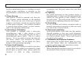
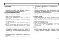
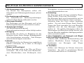
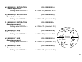
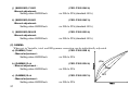
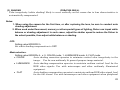
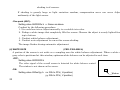
3-CCD Color Camera
MODEL HV-F31F
HV-F22F
OPERATION MANUAL
Please read this operation manual carefully for proper operation, and keep it for future reference.
Note:
The model and serial numbers of your product are important for you to keep for your convenience and
protection. These numbers appear on the nameplate located on the bottom of the product. Please record these
numbers in the spaces provided below, and retain this manual for future reference.
Model No.
Serial No.
Hitachi Kokusai Electric Inc.
IMPORTANT SAFETY INSTRUCTIONS
1. Read Instructions
All the safety and operating instructions should
be read before the product is operated.
2. Retain Instructions
The safety and operating instructions should be
retained for future reference.
3. Heed Warnings
All warnings on the product and the operating
instructions should be adhered to.
4. Follow Instructions
All operating and use instructions should be
followed.
5. Cleaning
Unplug this product from the wall outlet before
cleaning. Do not use liquid cleaners or aerosol
cleaners. Use a damp cloth for cleaning.
6. Attachments
Do not use attachments not recommended by the
product manufacturer as they may cause
hazards.
7. Water and Moisture
Do not use this product near water - for example,
near a bath tub, wash bowl, kitchen sink, or
laundry tub; in a wet basement; or near a
swimming pool; and the like.
8. Accessories
Do not place this product on an unstable cart,
stand, tripod, bracket, or table. The product may
fall, causing serious injury to a child or adult, and
serious damage to the product. Use only with a
cart, stand, tripod, bracket, or table recommended
by the manufacturer, or sold with the product.
Any mounting of the product should follow the
manufacturer's instructions, and should use a
mounting accessory recommended by the
manufacturer.
9. Moving
A product and cart combination should be moved
with care.
Quick stops, excessive force, and uneven surfaces
may cause the product and cart combination to
overturn.
10. Ventilation
Slots and openings in the cabinet are provided for
ventilation and to ensure reliable operation of the
product and to protect it from overheating, and
these openings must not be blocked or covered.
The openings should never be blocked by placing
the product on a bed, sofa, rug, or other similar
surface. This product should not be placed in a
A
built-in installation such as a bookcase or rack
unless proper ventilation is provided or the
manufacturer's instructions have been adhered
to.
11. Power Sources
This product should be operated only from the
type of power source indicated on the marking
label. If you are not sure of the type of power
supply to your home, consult your product dealer
or local power company. For products intended
to operate from battery power, or other sources,
refer to the operating instructions.
12. Grounding or Polarization
This product is equipped with a three-wire
grounding-type plug a plug having a third
(grounding) pin. This plug will only fit into a
grounding-type power outlet. This is a safety
feature. If you are unable to insert the plug into
the outlet, contact your electrician to replace
your obsolete outlet. Do not defeat the safety
purpose of the grounding-type plug.
13. Power-Cord Protection
Power-supply cords should be routed to that they
are not likely to be walked on or pinched by items
placed upon or against them, paying particular
attention to cords at plug, convenience
B
receptacles, and the point where they exit from
the product.
14. Lightning
For added protection for this product during a
lightning storm, or when it is left unattended and
unused for long periods of time, unplug it from
the wall outlet. This will prevent damage to the
product due to lightning and power-line surges.
15. Overloading
Do not overload wall outlets, extension cords or
integral convenience receptacles as this can result
in a risk of fire or electric shock.
16. Object and Liquid Entry
Never push objects of any kind into this product
through openings as they may touch dangerous
voltage points or short-out parts that could result
in a fire or electric shock. Never spill liquid of
any kind on the product.
17. Inflammable and Explosive Substance
Avoid using this product where there are gases,
and also where there are inflammable and
explosive substances in the immediate vicinity.
18. Heavy Shock or Vibration
When carrying this product around, do not subject
the product to heavy shock or vibration.
19. Servicing
Do not attempt to service this product yourself as
opening or removing covers may expose you to
dangerous voltage or other hazards. Refer all
servicing to qualified service personnel.
20. Damage Requiring Service
Unplug this product from the wall outlet and
refer servicing to qualified service personnel
under the following conditions:
a.When the power-supply cord or plug is
damaged.
b.If liquid has been spilled, or objects have fallen
into the product.
c. If the product has been exposed to rain or
water.
d.If the product does not operate normally by
following the operating instructions. Adjust
only those controls that are covered by the
operating instructions as an improper
adjustment of other controls may result in
damage and will often require extensive work
by a qualified technician to restore the product
to its normal operation.
e. If the product has been dropped or damaged in
any way.
f. When the product exhibits a distinct change in
performance-this indicates a need for service.
21. Replacement Parts
When replacement parts are required, be sure the
service technician has used replacement parts
specified by the manufacturer or have the same
characteristics as the original part.
Unauthorized substitutions may result in fire,
electric shock, or other hazards.
22. Safety Check
Upon completion of any service or repairs to this
product, ask the service technician to perform
safety checks to determine that the product is in
proper operating condition.
23. Wall or Ceiling Mounting
The product should be mounted to a wall or
ceiling
only
as
recommended
by
the
manufacturer.
24. Heat
The product should be situated away from heat
sources such as radiators, heat registers, stoves,
or other products (including amplifiers) that
produce heat.
C
WICHTIGE SICHERHEITSANWEISUNGEN
1. Alle Anweisungen lesen
Vor Betrieb des Erzeugnisses sollten alle
Sicherheits-und Bedienungsanleitungen gelesen
werden.
2. Die Anweisungen aufbewahren
Die Sicherheits-und Bedienungsanleitungen
sollten fünftigen Bezug aufbewahrt werden.
3. Warnungen beachten
Die Warnungen auf dem Erzeugnis und in den
Bedienungsanleitungen solten beachtet werden.
4. Anweisungen befolgen
Alle Bedienungsanleitung-und
Verwendungsanweisungen sollten befolgt werden.
5. Reinigung
Den Stecker des Geräts vor Reinigung aus der
Steckdose ziehen. Keine flüssigen Reinigungsmittel
oder Aerosolreiniger verwenden. Zum Reinigen
einen feuchten Lappen verwenden.
6. Zubehör
Nur vom-Hersteller des Erzeugnisses empfohlenes
Zubehör verwenden, da es sonst zu Störungen
kommen kann.
7. Wasser und Feuchtigkeit
Dieses Erzeugnis nicht in der Nähe von Wasser
verwenden - z.B, in der Nähe einer Badewanne,
eines Waschbeckens, einer Küchenspüle, eines
D
Waschzubers, in einem nassen Keller, in der Nähe
eines Schwimmbeckens usw.
8. Aufstellung
Das Erzeugnis nicht auf einen unstabilen Wagen,
Stand, Dreifuß, Träger oder Tisch stellen.
Das Erzeugnis kann sonst herunterfallen und ein
kind oder einen Erwachsenen schwer verietzen.
Außerdem kann das Gerät schwer beschädigt
werden. Nur mit einem Wagen, Stand, Dreifuß,
Träger oder Tisch verwenden, der vom Hersteller
empfohlen oder mit dem Erzeugnis verkauft
worden ist. Für jegliche Anbringung sollten die
Anweisungen des Herstellers befolgt werden, und
das vom Hersteller empfohlene Anbringungszubehör
sollte verwendet werden.
9. Eine Kombination von Erzeugnis und Wagen
sollte vorsichtig bewegt werden
Schneller Halt, übermäßige Krafteinwirkung und
unebene Oberflächen können Umkippen der
kombination
von
Erzeugnis
und
Wagen
verursachen.
10. Ventilation
Schlitze und Öffnungen im Gehäuse dienen der
Ventilation. Sie sind für zuverlässigen Betrieb
des Gerätes und Schutz vor Überhitzung
erforderlich und dürfen nicht blockiert oder abgedeckt
werden.
Die Öffnungen sollten niemals dadurch blockiert
werden, daß, das Gerät auf ein Bett, ein Sofa,
einen Teppich oder eine ähnliche Oberfläche
gestellt wird.
Das Gerät sollte nur dann in Einbauinstallierung
wie in einem Bücherschrank oder einem Gestell
verwendet
werden,
wenn
angemessene
Ventilation
vorgesehen
ist
bzw.
Die
Anweisungen des Herstellers befolgt worden
sind.
11. Stromversorgung
Dieses Erzeugnis sollte nur an der auf dem
Typenschild angegebenen Stromversorgungsart
betrieben werden. Wenn Sie nicht sicher sind,
was für eine Stromversorgung Sie haben, so
wenden Sie sich bitte an Ihren Erzeugnishändler
oder an das lokale Elektrizitätswerk. Beziehen
Sie sich für Batteriebetrieb oder andere
Stromquellen vorgesehene Erzeugnisse bitte auf
die Bedienungsanleitungen.
12. Erdung oder Polarisierung
Dieses
Erzeugnis
ist
mit
einem
Schutzkontaktstecker mit drei Leitern ausgerüstet,
mit einem Erdungskontakt. Dieser Stecker paßt
nur in ein schuko-Steckdose.
Dies ist eine
Sicherheitsmaßnahme.
Wenn Sie den Stecker
nicht in die Steckdose stecken können, so wenden
Sie sich bitte an ihren Elektriker, damit er die
veraltete Schuts des Schutzkontaktsteckers
unwirksam.
13. Netzkabelschutz
Netzkabel sollten so verlegt werden, deß möglichst
nicht darauf getreten wird und daß sie nicht
eingeklemmt werden, mit besonderer Beachtung
der kabel an Stackern, Verlängerungskabeln und
dem Austritt des Kabels aus dem Erzeugnis.
14. Blitzschlag
Für zusätzlichen Schutz des Erzeugnisses während
eines Gewitters oder bei Nichtverwendung für
lange Zeit den Stecker aus der Steckdose ziehen.
Dies verhütet Beschädigung durch Blitzschlag und
Netzspannungsstöße.
15. Überlastung
Wandsteckdosen,
Verlängerungskabel
und
eingebaute
Bequemlickkeitssteckdosen
nicht
überlasten, da dies Feuer oder elektrischen
Schlag verursachen kann.
E
16. Eindringen von Fremdkörpern und Flüssigkeit
Niemals Objekte irgendwelcher Art durch die
Öffnungen in das Gerät schieben, da diese unter
hoher Spannung stehende Teile berühren oder
kurzschließen können, wodurch es zu Feuer oder
elektrischem Schlag kommen kann. Niemals
Flüssigkeiten irgendwelcher Art auf das
Erzeugnis verschütten.
17. Entflammbare und explosive Substanzen
Vermeiden Sie Verwendung dieses Erzeugnisses
an Orten mit Gasen bzw. entflammbaren oder
explosiven
Substanzen
in
der
direkten
Umgebung.
18. Starke stöße oder Vibrationen
Setzen Sie das Erzeugnis beim Transport nicht
starken Stößen oder Vibrationen aus.
19. Wartung
Versuchen Sie nicht, dieses Erzeugnis Selbst zu
warten, da Sie sich durch Öffnen bzw.
Entfernen von Abdeckungen hohen Spannungen
und sonstigen Gefährdungen ausserzen können.
Beziehen Sie sich für jegliche Wartung auf
qualifiziertes Wartungspersonal.
20. Beschädigung, die Wartung erfordert
Ziehen Sie den Stecker dieses Erzeugnisses aus
der Steckdose und wenden Sie sich an
F
qualifiziertes Wartungspersonal, wenn eine der
folgenden Bedingungen vorliegt:
a. Wenn das Netzkabel oder der Stecker
beschädigt ist.
b. Bei
Eindringen
von
Flüssigkeit
oder
Fremdkörpern in das Gerät.
c. Wenn das Erzeugnis Regen oder Wasser
ausgesetzt worden ist.
d. Wenn das Erzeugnis bei Befolgen der
Bedienungsanleitungen
nicht
normal
funktioniert.
Nur die Regelelemente verstellen, die in den
Bedienungsanleitungen behandelt werden, da
unangemessene
Einstellung
anderer
Regelelemente Beschädigung verursachen kann
und oft beträchtliche Arbeit durch einen
qualifizierten Techniker erfordert, um das
Erzeugnis wieder, zu normalem Betrieb
zurückzubringen.
e. Wenn das Erzeugnis fallen gelassen oder
beschädigt worden ist.
f. Wenn das Erzeugnis eine klare Änderung in
der Leistung zeigt-dies weist darauf hin, daß
Wartung erforderlich ist.
21. Ersatzteile
Wenn Ersatzteile erforderlich sind, darauf
achten, daß der Wartungstechniker nur die vom
Hersteller festgelegten Ersatzteile oder Teile mit
den
gleichen
Charakteristiken
wie
die
ursprünglichen Teile verwendet. Unautorisierte
Ersatzteile können Feuer, elektrischen Schlag
oder sonstige Gefährdungen verursachen.
22. Sicherheitsprüfung
Bitten Sie den Wartungstechniker nach der
Vollendung von Wartung oder Reparaturarbeiten
an diesem Erzeugnis um die Durchführung von
Sicherheitsprüfungen, um zu bestimmen, daß das
Erzeugnis im angemissenen Betriebszustand ist.
23. Anbringung an der Wand oder an der Decke
Das Erzeugnis sollte nur entsprechend den
Empfehlungen des Herstellers an einer Wand
oder an der Decke angebracht werden.
24. Wärme
Das Erzeugnis sollte fern von Wärmequellen wie
Radiatoren, Heizwiderständen, Öfen und anderen
Wärme erzeugenden Erzeugnissen (einschließlich
Verstärkern) aufgestellt werden.
G
MISES EN GARDE IMPORTANTES
1. Lire les instructions
Lire toutes les instructions de sécurité et de
fonctionnement avant de faire fonctionner
l’appareil.
2. Conserver ces instructions
Conserver les instructions de sécurité et de
fonctionnement á des fins de référence ultérieure.
3. Tenir compte des avertissements
Tous les avertissements qui figurent sur
l’appareil et dans le mode d’emploi devront être
respectés.
4. Observer les instructions
Observer
toutes
les
instructions
de
fonctionnement et d’utilisation.
5. Nettoyage
Avant de procéder au nettoyage, débrancher
l’appareil de la prise secteur. Ne pas utiliser
de produits de nettoyage liquides ou en aérosol.
Nettoyer l’appareil avec un chiffon humide.
6. Fixations
Ne pas utiliser de fixations non recommandées
par le fabricant de l’appareil car elles
pourraient être source de danger.
7. Eau et humidité
Ne pas utiliser l’appareil á proximité d’eau-ar exemple
prés d’une baignoire, d’un lavabo, d’un évier
H
ou d’un bac á lessive, dans un sous-sol humide,
ou prés d’une piscine, etc.
8. Accessoires
Ne pas placer l’appareil sur un chariot, un socle,
un pied, un support ou one table instables
L’appareil pourrait tomber, blessant griévement
des enfants ou des adultes, et étant sérieusement
endommagé.
Utiliser exclusivement le chariot, le socle, le pied,
le support ou la table recommandés par le
fabricant, ou vendus avec l’appareil. Pour tout
montage de l’appareil, respecter les instructions
du fabricant, et utiliser á cette fin l’accessoire de
montage recommandé par le fabricant.
9. L’appareil monté sur son chariot devra être
déplacé avec précaution
Des arrêts brusques, une force excessive et des
surfaces irréguliéres pourraient provoquer le
renversement de l’ensemble appareil-chariot.
10. Ventilation
Les fentes et les ouvertures du coffret sont
prévues pour la ventilation ainsi que pour
garantir un fonctionnement en toute sécurité de
l’appareil et le protéger de toute surchauffe, et
ces
ouvertures ne devront donc être ni
obstruées ni recouvertes. Ne jamais obstruer les
ouvertures en placant l’appareil sur un lit, un
sofa, un tapis ou toute surface similaire. Ne
jamais placer l’appareil dans un support confiné,
par exemple une bibliothéque ou une é tagé re,
sans ventilation suffisante ou sans repecter les
instructions du fabricant.
11. Sources d’allmentation
L’appareil devra être alimenté exclusivement sur
le type d’alimentation indiqué sur l’étiquette
signalétique.
Sil’on n’est pas sûr du type
d’alimentatio du local, consulter le revendeur de
l’appareil ou la compagnie d’électricité locale.
Pour les appareils qui fonctionnent sur batterie
ou sur d’autres sources, voir le mode d’emploi.
12. Mise á la terre ou polarisation
L’appareil est doté d’une fiche trifilaire avec mise
á la terre, dont la troisiéme broche assure la mise
á la terre. Cette fiche ne rentrera que dans les
prises trifilaires de mise á la terre. Ceci est une
mesure de sécurité. Si la fiche ne rentre pas
dans la prise, faire remplacer la prise désuéte par
un électricien.
Ne pas rendre vaine la measure de sécurité
assurée par cette prise avec mise á la terre.
13. Protection du cordon d’alimentation
Acheminer les cordons d’alimentation de facon
qu’on ne risque pas de marcher dessus ou de les
coincer sous un objet placé dessus ou contre eux.
Faire particuliérement attention aux fiches des
cordons, á la proximité des prises, et á l’endroit oú
ils ressortent de l’appareil.
14. Foudre
Pour renforcer la protection de l’appareil pendant
un orage, ou si l’on s’en éloigne ou qu’on reste
longtemps sans l’utiliser, le débrancher de la
source d’alimentation. Ceci permettra d’éviter
tout dommage de l’appareil dú á la foudre et aux
surtensions de ligne.
15. Surcharge
Ne pas surcharger les prises, rallonges et prises
multiples car cela pourrait entraîner un risque de
feu ou de choc électrique.
16. Pénétration d’objets et de liquides
Ne jamais enfoncer d’objets d’aucune sorte dans
les ouvertures de l’appareil car ils pourraient
toucher des points de tension dangereuse ou
court-circuiter des piéces, ce qui pourrait
I
provoquer un feu ou un choc électrique. Ne
jamais renverser de liquide d’aucune sorte sur
l’appareil.
17. Substances inflammabes et explosives
Eviter d’utiliser l’appareil en présence de gaz,
ainsi qu’á proximité immédiate de substances
inflammables et explosives.
18. Chocs ou vibrations violents
Lorsqu’on transporte l’appareil, ne pas le
soumettre á des chocs ou des vibrations violents.
19. Réparations
Ne pas tenter de réparer l’aapareil soi-même car
le fait d’ouvrir ou de retirer les caches risque
d’exposer l’utilisateur á des tensions dangereuses
notamment.
Confier toute réparation á un
personnel qualifié.
20. Dommages nécessitant réparations
Débrancher l’appareil de la source d’alimentation
et confier les réparations á un personnel qualifié
dans les cas suivants:
a. Lorsque le cordon d’alimentation ou sa fiche
sont endommagés
b. Si du liquide s’est renversé sur l’appareil ou
que des objets sont tombés dedans
c. Si l’appareil a été exposé á la pluie ou á l’eau.
J
d. Si l’appareil ne fonctionne pas normalement
lorsqu’on observe les instructions d’utilisation.
Ne régler que les commandes couvertes par le
mode d’emploi ; en effet, un réglage incorrect
des autres commandes pourrait entrainer des
dommages et nécessiteront souvent des travaux
de réparation coûteux par un technicien qualifié
pour remettre l’appareil en état de marche.
e. Si l’appareil est tombé ou qu’il a été
endommagé.
f. Si l’appareil affiche une nette modification de
ses performances, cela signifie qu’il a besoin
d’être réparé.
21. Piéces de rechange
Si l’on a besoin de piéces de rechange, veiller á ce
que le technicien de réparation utilise
exclusivement les piéces de rechange spécifiées
par le fabricant ou des piéces ayant les mêmes
caractéristiques que les piéces d’origine. Les
piéces de rechange non autorisées risquent de
provoquer un feu, un choc électrique et autres
dangers.
22. Vérificaton de sécurité
Aprés tout travail d’entretien ou de réparation de
l’appareil, demander au technicien de réparation
d’effectuer les vérifications de sécurité pour
s’assurer que l’appareil est en bon état de
marche.
23.Montage au mur ou au plafond
L’appareil ne pourra être monté au mur ou au
plafond que de la maniére recommandée par le
fabricant.
24. Chaleur
Eloigner l’appareil des sources de chaleur, telles
que
radiateurs,
appareils
de
chauffage,
cuisiniéres, et de tour produit engendrant de la
chaleur (y compris les amplificateurs).
K
IMPORTANT NOTICE
For USA
These products have been tested and found to
comply with the limits for a Class A digital
device, pursuant to Part 15 of the FCC Rules.
These limits are designed to provide
reasonable
protection
against
harmful
interference when the equipment is operated
in a commercial environment.
This
equipment generates, uses, and can radiate
radio frequency energy and, if not installed
and used in accordance with the instruction
manual, may cause harmful interference to
radio communications.
Operation of this
product in a residential area is likely to cause
harmful interference in which case the user
will be required to correct the interference at
his own expense.
WARNING
Changes or modifications not expressly
approved by Hitachi Denshi responsible for
compliance could void the user’s authority to
operate the equipment.
L
For Canada
This product does not exceed the class A/class
B limits for radio noise emissions from digital
apparatus as set out in the radio interference
regulations.
Le présent appareil n’émet pas de bruits
radioélectriques
dépassant
les
limités
applicable aux appareils numériques de classe
A prescrites dans le rVglement sur le
brouillage radioélectrique édicter par le
ministére des communications du canada.
Table of contents
IMPORTANT SAFETY INSTRUCTUIONS ・・ A
IMPORTANT NOTICE ・・・・・・・・・・・・・・・・・・・ L
Table of contents ・・・・・・・・・・・・・・・・・・・・・・・・・ M
Standard composition ・・・・・・・・・・・・・・・・・・・・・ 1
CD-ROM ・・・・・・・・・・・・・・・・・・・・・・・・・・・・・・・・・ 1
Overview ・・・・・・・・・・・・・・・・・・・・・・・・・・・・・・・・ 3
Features ・・・・・・・・・・・・・・・・・・・・・・・・・・・・・・・・・ 3
Notes to users ・・・・・・・・・・・・・・・・・・・・・・・・・・・・ 4
Important safety notes ・・・・・・・・・・・・・・・・・・・ 4
Operating considerations ・・・・・・・・・・・・・・・・ 4
CCD properties ・・・・・・・・・・・・・・・・・・・・・・・・・ 5
System example ・・・・・・・・・・・・・・・・・・・・・・・・・・・ 7
Section names and functions ・・・・・・・・・・・・・・・ 8
Connectors ・・・・・・・・・・・・・・・・・・・・・・・・・・・・・・・ 9
LENS ・・・・・・・・・・・・・・・・・・・・・・・・・・・・・・・・・・・ 10
Camera mounting ・・・・・・・・・・・・・・・・・・・・・・・・ 11
Control and status register (CSR) ・・・・・・・・・ 12
IIDC standard CSR・・・・・・・・・・・・・・・・・・・・・ 13
Advanced CSR ・・・・・・・・・・・・・・・・・・・・・・・・・ 20
Image color reproduction and
Color balance related CSR ・・・・・・・・・・ 20
Image quality related CSR ・・・・・・・・・・・ 24
Image level related CSR ・・・・・・・・・・・・・ 28
CSR related to other functions ・・・・・・・ 32
Specifications ・・・・・・・・・・・・・・・・・・・・・・・・・・・・ 36
Input/Output Signals ・・・・・・・・・・・・・・・・・・・・・ 38
Trigger operation and timing chart
HV-F31F・・・・・・・・・・・・・・・・・・・・・・・・・・・・・・・・・ 41
HV-F22F・・・・・・・・・・・・・・・・・・・・・・・・・・・・・・・・・ 43
External sync operation timing ・・・・・・・・・・・・ 45
Dimensions ・・・・・・・・・・・・・・・・・・・・・・・・・・・・・・ 46
M
Standard composition
Check when unpacking.
Camera HV-F31F/HV-F22F ・・・・・・・・・・・・・・・・・・・・・・・・・・・・・・・・・・・・・・・・・・・・・・・・・・・・・・・・・・・・・ 1
DC IN/SYNC plug (HR10A-10P-12S) ・・・・・・・・・・・・・・・・・・・・・・・・・・・・・・・・・・・・・・・・・・・・・・・・・・ 1
CD ROM (IIDC Driver and demonstration viewer software) ・・・・・・・・・・・・・・・・・・・・・・・・・・・ 1
Operation manual ・・・・・・・・・・・・・・・・・・・・・・・・・・・・・・・・・・・・・・・・・・・・・・・・・・・・・・・・・・・・・・・・・・・・・・・ 1
CD-ROM
An IEEE1394 driver and demonstration viewer software that displays an image to PC monitor and
control the camera functions are included within the belonging CD-ROM.
As for the installation procedure of an
IEEE1394 driver and viewer software,
please read the installation manual and
operation manual within CD-ROM
carefully.
Viewer Software
1
NOTE:
1) The included driver and also demonstration software within CD-ROM operate only in Windows 98
SE/ME/2000/XP.
2) The viewer software may not operate normal when it is used for the other camera, because
software for HV-F31F and HV-F22F.
3) In the case that it stopped normal operating during the use of viewer software, stop a viewer
software, turn off and on the camera power supply or pull and push the IEEE1394 cable, execute
viewer software once again.
4) In the case that the performance (the CPU clock, installation memory etc.) of PC is not sufficient,
viewer software may not execute normally. Please use PC of following specification.
Item
CPU
Memory
Display Card
Interface Card
Operating System
Others
Specifications
Intel Celeron 533MHz or more
256MByte or more
24bit RGB color display card or more
built-in OHCI IEEE1394 port or PCI-Card or PC-Card
Windows 98SE / Me / 2000 / XP
DirectX 8.0 or more
5) Hitachi kokusai Electric. Inc does not guarantee it, regarding the faulty, damage of the hardware
and also software of the customer by a driver and also viewer software.
2
Overview
The Hitachi HV-F31F/HV-F22F are high precision 3CCD progressive scan color camera, which has
single chip digital processing LSI, a C mount prism, three 1/3-inch 800,000 pixels (HV-F31F) / 1/2-inch
1,450,000 pixels (HV-F22F) square CCDs , and an IEEE1394 digital output.
A newly developed multi-functional LSI use the accurate 14 bit digital processing technology, which
performs the high picture quality signal processing and the picture compensating functions, beyond the
capability of the other conventional analog cameras. The IEEE1394 interface reduces the system cost
without an image capturing board and special connecting cable.
Features
• Camera signal processor is single chip LSI.
The Hitachi’s most advanced technology (0.18 um design process, 1.8V internal core drive voltage)
produces a single newly developed ultra LSI chip (3 million gates), and contributes to the downsizing
and the low power of the camera. In addition, the 12-bit A/D converter and 14 bit internal processor
provide high S/N and wide dynamic range.
• High quality picture
Excellent color reappearance and high definition are materialized by CCD with a high sensitivity micro
lens and LSI signal processing technology.
• 6 vector masking
Independent six colors masking is the Hitachi innovation for optimizing color balance. The saturation
and the hue of 6 colors (Red, blue, green, cyan, magenta and yellow) are adjusted independently to
deliver the best color in image capture, microscope and other applications.
• Auto white shading compensation
Color shading due to the aberration of C mount lens is automatically compensated (reduced).
3
Notes to users
Important safety notes
Use this camera with a 12 VDC power supply.
Observe that flammable objects, water or metal
do not enter the camera interior. These may
lead to failure or accident.
Do not modify the camera or use the camera with
external covers removed.
These may cause
failure, void any warranties and pose a safety
hazard.
Stop using the camera at the approach of an
electrical storm (thunder audible). Protect the
camera from rain if using it outdoors.
In event the camera shows any abnormality,
switch off the camera and disconnect the power
cord.
Contact a Hitachi Denshi service
representative.
Operating considerations
Power supply
Check that the supplied voltage is between 10.5
and 15 VDC. Inadequate voltage can affect color
fidelity and cause noise, while voltage over 15 V
can damage the camera.
Connectors
Confirm the power is off before connecting or
disconnecting a signal cable. Grasp connectors
by the body, not the attached wires.
Lens
The correct lens is important for deriving
optimum performance from the camera. Consult
a Hitachi Denshi dealer for a selection of fine
lenses according to the application.
Installation and storage sites
The following types of environment can impair
performance, lead to damage, pose safety hazards
and shorten the useful life of the camera. Select
the sites for installing the storing the camera
carefully.
• Direct sunlight, rain or snow
• Flammable or corrosive gasses
• Very hot or cold (beyond 0 to 4 ℃ operating,
-20 to 60 ℃ storage)
• Humid or dusty
• Exposed to vibration or shock
• Strong electrical or magnetic fields
• Exceptionally strong light
•
Continuous operation
In situations where the camera is used
continuously for long periods of time, the ambient
temperature should be kept below 40 ℃ in order
to avoid accelerated deterioration of internal
parts and to derive maximum long-term
reliability.
4
Cleaning
A photographer’s blower or lens brush can be used for clearing dust from the lens and optical filters.
Wipe dust from the case with a soft dry cloth. If soiling is severe, moisten the cloth with a solution of neutral
detergent. Afterwards, wipe the cover with a dry cloth.
Do not use petroleum distillates, alcohol or spray type cleaners.
Transportation
Remove the lens (install lens mount cap) and other attachments. Pack the camera carefully in its original or
equivalent container. Use ample cushioning to protect the camera from physical shock.
CCD properties
The following phenomena are inherent to a charge coupled device imaging element and do not indicate
malfunction.
1) Smear and blooming
Vertical bands are visible when a strong light enters the scene. Adjust the camera aiming direction
carefully to avoid strong direct or reflected light.
2) Fixed pattern noise
High ambient temperature can cause fixed pattern noise to appear throughout the scene.
5
3) Moire
Interaction between patterns can produce an additional "phantom" pattern to appear. The CCD picture
elements (pixels) are arranged in a pattern, which can interact with a pattern in the scene (e.g., a
performer wearing a finely striped necktie) to result in a Moire pattern. The effect should be considered
when selecting costumes, props and other scene elements.
4) Ghosting
Strong direct or reflected light near an object of interest can cause ghosting of the object to appear in the
picture. The effect is more obtrusive with certain iris settings and lens types. Select the scene layout
and camera pointing direction carefully in order to avoid this effect.
6
System example
Computer Image
Processing &
FA
PC
Lens
H V -F31F/F22
F
Camera Cable
C-201KSM
/C501KSM
/C102KSM
Junction Box
JU-M1A
Laptop PC
External
T rigge r
AC adaptor
7
Section names and functions
Camera mounting
screw holes
Lens mount
(C mount)
DC IN/SYNC connector
Connect to +12 VDC power supply.
Input for external HD/VD and sync
signals.
TRIG IN connector
External trigger signal input
Pilot lamp
Light when power is
supplied.
Status lamp
Flashes when
transmitting
IEEE1394 connector (see Note)
IEEE1394 cable computer side
IEEE1394 connector end
Camer mounting
screw holes
Note
When power is supplied from IEEE1394,
check for proper current and voltage. If not
correctly indicated, a separate power supply
is required.
8
Connector
1. IEEE1394 connector
Pin No.
1
2
3
4
5
6
9
Signal designation
+12V input
GND
TPBTPB+
TPATPA+
2
4
6
1
3
5
2. DC IN/SYNC connector
(HR10A-10R-12PB(01))
Pin NO. Signal designation
1
GND
2
+12V input
3
GND
4
FLASH OUT
5
GND
6
HD IN
7
VD IN
8
GND
9
TRIG (H)
10
TRIG (C)
11
+12V input
12
GND
Plug:HR10A-10P-12S
Lens
CAUTION:
Observe the dimensions of the lens mounting
selection as illustrated at the right.
If the dimensions are not observed, do not use
such a lens, because the lens and the camera will
be damaged.
Lens optics
Selecting a lens
The proper lens is important for obtaining
adequate performance from the camera.
Especially in the case of a three elements CCD
system C mount camera, the lens incidence
and exit distances are important. If separation
is too short, color irregularity Is apt to occur at
the top and bottom of the image.
Conversely if too long, where the lens iris is a
nearly fully open, resolution is impaired, while
shading and flare can seriously detract from
image quality. When using 3 CCD color system
camera, it is also recommended to use a lens
designed for this purpose.
Lens flange
HV-F31F: Max. 4.3mm
HV-F22F: Max. 4.0mm
10
Camera mounting
The camera is provided with threaded screw holes at the top and bottom.
tripod or a mounting bracket.
Screw type: U 1/4-20
Length: 4.5 to 6 mm
L
Screws longer than 6 mm can
cause internal damage, while
less than 5 mm prevents secure
fastening and risks dropping to
cause damage and injury.
11
These allow mounting to either a
Control and Status register (CSR)
HV-F31F and HV-F22F differ from earlier conventional cameras in that camera functions can be set by
entering predetermined setting commands in the Control and Status register (CSR) of the 1394-based
Digital Camera Specification Ver. 1.30.
Common and camera-specific CSR register setting operations are described below.
Indication example: Function name
(CSR: xxxx xxxx h)
Function description
Lower 32 bits of 64 bit CSR address are displayed.
ex: F0F0 0800 h
means BUS_ID, NODE_ID, FFFF F0F0 0800 h.
12
1. IIDC Standard CSR
(1) BRIGHTNESS
(CSR: F0F0 0800 h)
Master black level is adjusted
-Manual adjustmentSetting value 820000xx h xx: 00h to FFh (standard 80h)
Can be set in range of 00h to FFh. Setting value to 00h side lowers black level. FFh side raises
black level.
(2) SHARPNESS
(CSR: F0F0 0808 h)
Sharpness level adjustment (object contour correction)
-Manual adjustmentSetting value 820000xx h xx: 00h to FFh (standard 80h)
Contour correction can be set in range of 00h to FFh. Setting value toward 00h side reduces
correction for softer contours. Setting toward FFh side increases correction for sharper contours.
(3) WHITE BALANCE
(CSR: F0F0 080C h)
White balance adjustment
-Manual adjustmentSetting value 820xx0yy h xx: 00h to FFh (B gain)
yy: 00h to FFh (R gain)
White balance is adjusted manually by adjusting R and B gain. Gain is reduced at 00h side and
raised at FFh side.
13
-One Push Auto White Balance (AWB)Setting value 86000000 h
State for automatic white balance adjustment.
-AUTO (ATW)Setting value 83000000 h
White balance is adjusted in real time (automatic tracking). An effective function when the scene
is subject to changes in color temperature of the light source. The speed for changing the color
temperature is selected by A. WHT SPEED.
(4) GAIN
(CSR: F0F0 0820 h)
Electrical sensitivity is adjusted.
-Manual adjustmentSetting value 82000xxx h
xxx: 000h to 0C0h (1dB ≒ 010h)
Adjusts electrical sensitivity in the range of 0 to 12 dB.
-AUTOSetting value 83000000 h
Gain is automatically adjusted in the range of 0 to 12 dB in response to light source brightness.
(5) SHUTTER
Sets electronic shutter speed.
-OFF (HV-F22:1/15sec, HV-F31:1/30) Setting value 80000000 h
Switches off shutter operation.
(CSR: F0F0-081C h)
14
-Manual adjustmentSetting value 82000xxx h
xxx: (HV-F22) 7C5h to B6Ch / (HV-F31) 789h to B27h
Electronic shutter can be set in the range of 4 to 1/100,000 second.
Shutter speed setting value can be derived as follows.
OFF_SPEED = 15 (HV-F22), 30 (HV-F31).
• Cause of shutter speed ≦ (1 / OFF_SPEED)
a) Setting value obtained from fluorescent time.
nnnh = 800h + log0.99( OFF_SPEED×”Shutter Speed”)
b) Fluorescent time obtained from setting value.
Shutter Speed[sec] = OFF_SPEED × 0.99(nnn―800h)
Ex. 1 Fluorescent time with HV-F31 = setting value nnn to obtain 1/100 second.
800h+ log0.99(30×(1/100))
= 800h+ log(30×(1/100)) / log0.99
= 878h
Ex. 2 Setting value nnn that produces 1/100 second fluorescent time with HV-F31F.
(1/30) × 0.99(878h-800h) = 1/100(sec)
• Cause of shutter speed > (1 / OFF_SPEED)
a) Setting value obtained from fluorescent time.
nnnh = 801h - ( OFF_SPEED×”Shutter Speed” )
b) Fluorescent time obtained from setting value.
15
Shutter Speed[sec] = (801h – nnn ) / OFF_SPEED
Example Fluorescent time = 1/7.5s usable as setting value nnn with HV-F31F.
801h - (30×(1/7.5)) = 7FDh
-AUTOSetting value 83000000 h
Auto electronic shutter operates to vary the shutter speed in the range of OFF to 1/100,000 second
in response to light source brightness.
If light is excessive, a suitable level is selected for maintaining a video output. This function is
effective when using microscope or other optical system without an automatic lens iris.
(6) AUTO EXPOSURE
(CSR: F0F0 0804 h)
At auto gain or shutter setting, the sensitivity is automatically adjusted to maintain the proper video
level.
-Manual adjustmentSetting value 820000xx h
xx: 00h to FFh (standard:80 h)
Video level decreases toward 00h and increases toward FFh.
(7) SATURATION
(CSR: F0F0 0814 h)
Color saturation is adjusted.
-Manual adjustmentSetting value 820000xx h
xx: 00h to FFh (standard: 80 h)
Saturation is reduced toward 00h and raised toward FFh.
16
Output
(8) GAMMA
(CSR: F0F0-0818 h)
Gamma correction is adjusted.
-OFFSetting value 80000000h
ON3
Gamma correction is set to OFF.
ON2
-Manual adjustmentSetting value 8200000x h x: 0- ON1, 1- ON2, 2- ON3, F- Variable
OFF
Positions 1,2 and 3 are effective for additionally fine adjustment
of RGB gamma.
ON1
• ON1: Dark component gradation reduced.
• ON2: Standard setting
Input
• ON3: Dark component gradation increased.
When setting to Variable, R GAMMA (CSR: F200 0054 h),
G GAMMA (CSR: F200 0058 h), B GAMMA (CSR: F200 005C h) of Setting value become to effect
and adjust the detail gamma.
(9) TRIGGER
Sets external trigger operating mode.
-OFFSetting value 80000000 h
Trigger function set to OFF
17
(CSR: F0F0 0830 h)
-Manual adjustmentSetting value 8x0y0000 h
x:2- LOW ACTIVE, 3- HIGH ACTIVE
y:0- MDOE0, 1- MODE1
Trigger mode polarity is switched at external signal values x and y.
See trigger operation details and timing chart (page 39).
(10) INITIALIZE
(CSR: F0F0 0000 h)
Return equipment to status at time of release from factory.
-InitializationSetting value 80000000 h
(11) MEMORY SAVE (EXECUTE)
(CSR: F0F0 0618 h)
Make back up of presently effective memory channels.
-BACK UP executeSetting value 80000000 h
(12) MEMORY SAVE (Ch SET)
(CSR: F0F0 0620 h)
Select channel carried out memory backup.
-channel setSetting value x0000000 h
x: 1- ch1, 2- ch2, 3- ch3, 4- ch4
(13) CURRENT MEMORY
(CSR: F0F0 0624 h)
Loading memory channel designating data
-LOAD BACK UPSetting value x0000000 h
x: 0- FACTORY SETUP, 1- ch1, 2- ch2, 3- ch3, 4- ch4
18
2. Advance CSR
2-1. Image color reproduction and color balance related CSR
(1) MASKING
(CSR: F200 0020 h)
RGB and Ye Cy Mg color saturation and hue can be separately varied (6 vector independent masking). Color
reproduction detail and fidelity are effectively enhanced.
When engaged, R saturation (CSR: F200 0024) - M hue ((CSR: F200 0050) can be set, with color phase
and saturation adjusted for each color phase.
-OFF-
Setting value 80000000 h
-ON-
Setting value 82000000 h
a) (MASKING) R SATURATION
-Manual adjustmentSetting value 820000xx h
b) (MASKING) Y SATURATION
-Manual adjustmentSetting value 820000xx h
c) (MASKING) G SATURATON
-Manual adjustmentSetting value 820000xx h
19
(CSR: F200 0024 h)
xx: 00h to FFh (standard: 80 h)
(CSR: F200 0028 h)
xx: 00h to FFh (standard: 80 h)
(CSR: F200 002C h)
xx: 00h to FFh (standard: 80 h)
d) (MASKING) C SATURATION
-Manual adjustmentSetting value 820000xx h
e) (MASKING) B SATURATION
-Manual adjustmentSetting value 820000xx h
f) (MASKING) M SATURATION
-Manual adjustmentSetting value 820000xx h
g) (MASKING) R HUE
-Manual adjustmentSetting value 820000xx h
h) (MASKING) Y HUE
-Manual adjustmentSetting value 820000xx h
i) (MASKING) G HUE
-Manual adjustmentSetting value 820000xx h
(CSR: F200 0030 h)
xx: 00hto FFh (standard: 80 h)
(CSR: F200 0034 h)
xx: 00h to FFh (standard: 80 h)
(CSR: F200 0038 h
xx: 00h to FFh (standard: 80 h)
R
(CSR: F200 003C h)
(FFh)
(FFh)
(00h)
(00h)
Y
Saturation
adjustment
M
xx: 00hto FFh (standard: 80 h)
(CSR: F200 0040 h)
Color phase
xx: 00h to FFh (standard: 80 h)
(CSR: F200 0044 h)
G
B
C
xx: 00h to FFh (standard: 80 h)
20
j) (MASKING) C HUE
-Manual adjustmentSetting value 820000xx h
k) (MASKING) B HUE
-Manual adjustmentSetting value 820000xx h
l) (MASKING) M HUE
-Manual adjustmentSetting value 820000xx h
(CSR: F200 0048 h)
xx: 00h to FFh (standard: 80 h)
(CSR: F200 004C h)
xx: 00h to FFh (standard: 80 h)
(CSR: F200 0050 h)
xx: 00h to FFh (standard: 80 h)
(2) GAMMA
When set to Variable, total and RB gamma correction can be individually adjusted.
a) (GAMMA) Total
(CSR: F200 0058 h)
- Manual adjustment Setting value 820000xx h
xx: 00h to FFh
c) (GAMMA) B ch
- Manual adjustment Setting value 820000xx h
21
(CSR: F200 0054 h)
xx: 00h to FFh
(CSR: F200 005C h)
xx: 00h to FFh
(FFh)
Output
b) (GAMMA) R ch
- Manual adjustment Setting value 820000xx h
(00h)
OFF
Input
(3) SHADING
(CSR:F200 0060 h)
Color irregularity (white shading) likely to occur vertically on the screen due to lens characteristics is
automatically compensated.
Notes:
1. When using the camera for the first time, or after replacing the lens, be sure to conduct auto
shading adjustment.
2. When used under fluorescent, mercury or other special types of lighting, flicker can impair white
balance or shading adjustment. In such cases, adjust the shutter speed to reduce the flicker to
the extent possible, then adjust white balance or shading.
-OFFSetting value 80000000 h
Set white shading compensation to OFF.
-Mode selectionSetting value 8200000x h x: 0- COLOR mode, 1- LUMINUNCE mode, 2- FLAT mode
• COLOR
:Auto shading correction operates to minimize vertical color irregularity in the
image. Use for non-uniformly lit general-purpose image material.
• LUMINANCE :Auto shading compensation operates to maintain uniform vertical level for the
RGB video signals. Use with microscopes and other uniformly illuminated
equipment.
• FLAT
:Auto shading compensation operates to maintain uniform RGB video signal level
for the full screen. Use with microscopes and other equipment when peripheral
22
shading is of concern.
If shading is grossly large or light variation random, compensation error can occur. Adjust
uniformity of the light source.
-One push (ASC)Setting value 8600000x h x: Same as above.
Conduct by the following procedure.
1. Use auto lens iris or adjust manually to a suitable iris value.
2. Pickup a white image that completely fills the screen. Observe the object is evenly lighted from
top to bottom.
3. Conduct white balance adjustment.
4. Conduct auto adjustment to correct for screen shading.
The image flashes during automatic adjustment.
(4) WHITE GATE
(CSR: F200-0098 h)
A portion of the screen is set aside as a sampling area for white balance adjustment. When a white or
gray color is positioned at this window, optimum white balance can be adjusted in real time.
-OFFSetting value 80000000 h
The video signal of the overall screen is detected for white balance control.
The window is not shown on the screen.
-ONSetting value 820xx0yy h xx: 00h to FFh ( H position)
yy: 00h to FFh ( V position)
23
Window
The window is displayed on the screen during AUTO or
ONE PUSH WHITE BALANCE operation for video signal detection.
The window horizontal position setting is xx, and vertical position setting is yy.
(5) BLACK BALANCE
(CSR: F200 0064 h)
Black balance is adjusted.
-Manual adjustmentSetting value 820xx0yy h xx: 00h to FFh (B black)
yy: 00h to FFh(R black)
-AUTO ADJUST (One Push) (ABB)Setting value 86000000 h
Conduct with oblique light, such as with closed lens iris.
2-2. Image quality related CSR
(1) SHARPNESS
Object contours can be finely adjusted.
a) (SHARPNESS) FREQ.
(CSR: F200 00B0 h)
Sharpness signal width can be set.
-Manual adjustmentSetting value 8200000x h
x: 0- LOW, 1- MID, 2- HIGH
• LOW: Width is thick.
• MID: Width set to standard.
• HIGH: Width set to fine.
24
b) (SHARPNESS) LEVEL DEPENDENT.
(CSR: F200 00B4 h)
Sharpness is decreased at levels below a certain amount. Used mainly to avoid noise enhancement in
dark signal components.
-Manual adjustmentSetting value 820000xx h
xx: 00h toFFh
Setting toward FFh reduces the sharpness level and expand the video signal level range.
c) (SHARPNESS) CLISP
(CSR: F200 00B8 h)
Below a certain level, the sharpness signal is removed to avoid appearing as noise.
too low, some blurring can occur in detailed components.
But if the level is set
-Manual adjustmentSetting value 820000xx h
xx: 00h to FFh
Setting toward 00h reduces sharpness level; setting toward FFh increases sharpness level.
d) (SHARPNESS) H/V BALANCE
(CSR: F200 00BC h)
Balance setting for horizontal and vertical sharpness level.
-Manual adjustmentSetting value 820000xx h
xx: 00h to FFh
Setting toward 00h reduces vertical sharpness level; setting toward FFh reduces horizontal
sharpness level.
25
e) (SHARPNESS) COLOR DTL Ch1
(CSR: F200 00C0 h)
Color detail can be adjusted in the range of the color phase sharpness level setting.
The color phase can be set in different ranges for channels 1 and 2. The color detail channel 1
width/level can be set in any combination. Select channel 1 or 2, then set the color phase for adjusting
detail.
-OFFSetting value 80000000 h
Color detail function is set to OFF.
-ON (Manual adjustment)Setting value 82000xyy h
x: 0- R, Y- 1, 2- G, 3- C, 4- B, 5- M (phase)
yy: 00h to FFh ( phase(fine) )
Select 6 color phases from x values and then fine adjust with yy.
-One Push (AUTO SETUP)Setting value 86000000 h
The currently displayed color phases are automatically set by AUTO SETUP.
f) (SHARPNESS) COLOR DTL Ch1 WIDTH/LEVEL (CSR: F200 00C4 h)
The effective phase range and sharpness level can be adjusted.
-Manual adjustmentSetting value 820xx0yy h
xx: 00h to FFh (Width)
yy: 00h to FFh (Level)
Set color phase range with xx value. Reduce range toward 00h; increase range toward FFh.
Select
26
range with Phase and position at color phase center to set.
Set sharpness level in range set by yy. Reduce sharpness toward 00h for a soft image.
sharpness toward FFh for a stark image. Channels 1 and 2 can be set independently.
Increase
g) (SHARPNESS) COLOR DTL Ch2
(CSR: F200 00C8 h)
Same function as COLOR DTL Ch1 (F200-00C0). (Ch 1 and 2 can be used as independent functions.)
h) (SHARPNESS) COLOR DTL Ch2 WIDTH/LEVEL (CSR: F200 00CC h)
Same function as COLOR DTL Ch1 (F200-00C4). (Ch 1 and 2 can be used as independent functions.)
Compress
Knee point
Output
(2) KNEE
(CSR: F200 00D4 h)
Image high luminosity component is compressed (knee corrected)
reducing gradation in high luminosity images.
-OFFSetting value 80000000 h
-Manual adjustmentSetting value 820000xx h
xx: 00h to FFh
Image compression level (knee point) decreases toward 00h
and increases toward FFh.
(FFh)
(00h)
-AUTOInput
Setting value 83000000h
The auto setting increases the light amount and the knee point is automatically adjusted to
compensate.
27
(3) DNR (Digital Noise Reduction)
(CSR: F200 00A0 h)
Improve S/N by digital noise reduction.
-OFFSetting value 80000000 h
-ONSetting value 8200000x h
x: 1- MODE1, 2- MODE2
Although MODE 2 provides greater noise reduction, there is some sacrifice in resolution.
2-3. Image level related CSR
(1) (A.E) PEAK/AVERAGE
(CSR: F200 0070 h)
Sets PEAK or AVERAGE signal level detection for the AUTO EXPOSURE function.
-Manual adjustmentSetting value 8200000x h
x: 0- 0/100, 1- 15/18, 2- 25/75, 3- 50/50
Set auto level control for Peak or Average in 4 steps of 50/50, 15/85, 25/75, or 0/100. At high
Average setting, background may be difficult to see in picture bright components. Increasing the
Peak setting may render spotlighted components easier to see.
(2) (A.E) SPEED
(CSR: F200 0074 h)
AGC and AES response speed
-Manual adjustment
Setting value 8200000x h
x: 0- SLOW, 1- MID, 2- FAST
• SLOW
: Scene brightness variation rate is sufficiently slow to allow stable observing of detail.
Allows a stable image when a strong light source enters the scene.
• STANDARD : Standard setting.
• FAST
: Scene brightness variation rate is too rapid to stable use of effects such as
28
microscope variable magnification.
(3) (A.E) GATE
(CSR: F200 0078 h)
AUTO EXPOSURE signal detect area (8 x 8) can be set as desired.
-OFFSetting value 80000000 h
The screen overall video signal is detected for AUTO EXPOSURE control.
-ONSetting value 82000000 h
GATE for detecting the AUTO EXPOSURE video signal is set in lines 1-2 to 7-8. The area is not
shown on the screen.
a) (A.E) GATE line1-2
-Manual adjustmentSetting value 820xx0yy h
b) (A.E) GATE line3-4
-Manual adjustmentSetting value 820xx0yy h
c) (A.E) GATE line5-6
-Manual adjustmentSetting value 820xx0yy h
29
(CSR: F200 007C h)
xx: LINE 1 ON/OFF data
yy: LINE 2 ON/OFF bit map data
(CSR: F200 0080 h)
xx: LINE 3 ON/OFF data
yy: LINE 4 ON/OFF data
(CSR: F200 0084 h)
xx: LINE 5 ON/OFF data
yy: LINE 6 ON/OFF data
d) (A.E) GATE line7-8
-Manual adjustmentSetting value 820xx0yy h
(CSR: F200 0088 h)
xx: LINE 7 ON/OFF bit map data
yy: LINE 8 ON/OFF bit map data
(A.E) GATE line1-2 to line7-8 setting examples
Screen detect areas
Setting values corresponding to detect areas
Detect area (ON): 1 Non-detect area (OFF): 0
GATE line1-2 xx values
GATE line1-2 yy values
7
0
0
6
0
0
5
0
0
4
0
0
3
0
0
2
0
0
1
0
0
0
0
0
GATE line3-4 xx values
0
0
0
0
0
0
0
0
GATE line3-4 yy values
0
0
1
1
1
1
0
0
GATE line5-6 xx values
0
1
1
1
1
1
0
0
GATE line5-6 yy values
0
1
1
1
1
1
0
0
GATE line7-8 xx values
0
1
1
1
1
1
0
0
GATE line7-8 yy values
0
1
1
1
1
1
0
0
Values for setting the above map detection area
(A.E) GATE line1-2: 82 00 00 00 h
(A.E) GATE line3-4: 82 00 00 3C h
(A.E) GATE line5-6: 82 07 C0 7C h
(A.E) GATE line7-8: 82 07 C0 7C h
30
2-4. CSR related to other functions
(1) FLASH
(CSR: F200 0018 h)
Adjusts flash signal timing for mode 0 trigger operation.
-OFFSetting value 80000000h
Flash signal output absent.
-Manual adjustmentSetting value 8200xyyy h x: 0-NARROW, 1- MIDDLE, 2- WIDE (pulse width)
yyy: 000h to FFFh ( START)
See flash signal pulse width and timing chart on page 41.
(2) BAR
Set to ON for Color Bars.
-OFFSetting value 80000000 h
-ONSetting value 82000000 h
(CSR: F200 00DC h)
(3) NEGA
On setting produces negative image.
-OFFSetting value 80000000 h
(CSR: F200 00E0 h)
31
-ON-
Setting value 82000000 h
(4) GL IN 75 ohm
(CSR: F200 00E4 h)
Impedance changes over of input to the GL signal.
-OFF( High Z)Setting value 80000000 h
-ON (75 ohm)Setting value 82000000 h
(5) H PHASE
(CSR: F200 00E8 h)
Horizontal phase can be adjusted.
-Manual adjustmentSetting value 820000xx h
xx: 00h to FFh
See setting range on page 42 “External sync timing”.
(6) PIXEL CONCEALMENT
Sets pixel concealment on/off.
-OFFSetting value 80000000 h
-ONSetting value 82000000 h
(CSR: F200 00F0 h)
(7) FOCUS
Setting register for focus data output.
32
a) FOCUS GATE (SIZE)
(CSR: F200 00F4 h)
Setting for focus data output area size.
-ONSetting value 820xx0yyh
xx: 00h to FFh (H size)
yy: 00h to FFh (V size)
b) FOCUS GATE (POSITION)
(CSR: F200 00F8 h)
Setting for focus data output area position.
-ONSetting value 820xx0yy h
xx: 00h to FFh (H position)
yy: 00h to FFh (V position)
c) FOCUS DETECTION
Return focus data.
-DATA00000000 h(MIN) to FFFFFFFF h(MAX)
(8) INDICATOR
Each type of indicator is displayed.
-OFFSetting value 80000000 h
(CSR:F200 00FC h) (read only)
(CSR: F200 0100 h)
-ON-
Setting value 8200000x h
33
x:1- display WHITE GATE、2- display FOCUS GATE
(9) AUTO SETUP STATE
(CSR: F200 01004 h) (read only)
Resulting data of One Push Auto White Balance (AWB), One push Auto BLACK Balance (ABB), One
push Auto Shading (ASC) and One Push (Color DTL Auto Setup) are shown.
-DATA-
000xyyzzh
x: 0- NON, 1- WHITE, 2- BLACK, 3- SHAD, 4- DTL
yy: Progress condition 00h- 0% , FF- 100%
zz: Result
00h
- Normal end
FFh
- under adjustment (busy)
11h to 26h - Error end
Result codes:
Procedure
11h:
Turn off the color bar
12h:
(WHITE BALANCE) change to Manual
13h:
Increase the intensity of illumination, turn lens iris to ward open direction, or
increase the gain to provide a proper video level.
14h:
Decrease the intensity of illumination, turn lens iris toward closed direction, or
decrease the gain to provide a proper video level.
15h:
The color temperature is too high, making it impossible to reach the optimum
value in adjustment. (If there is no problem in practical application, use the
camera under the current condition.)
34
16h:
18h:
1Fh:
24h:
25h:
26h:
35
Add a filter to the lens or illumination to decrease the color temperature.
The color temperature is too low, making it impossible to reach the optimum value.
(If there is no problem in practical application, use the camera under the current
condition.) Add a filter to the lens or illumination to increase the color
temperature.
Carry out auto setup again. If this message appears in repeated attempts, it is
necessary to inspect the inside of the camera. In this case, notify your local
Hitachi Denshi sales agent or Hitachi Denshi service office
The color saturation is too low, making it impossible to reach the optimum value
Release the long shutter mode.
Release the external trigger mode.
Change a frame rate to the one under 30fps (HV-F22F only)
Specification
1)
2)
3)
Optical system
Imaging system
Picture elements
4)
5)
6)
Total pixels
Effective pixels
Pixel size
Effective image area
Scanning system
Sync system
Standard sensitivity
7)
8)
9)
10)
11)
Geometric distortion
Registration
Vertical contour compensation
Lens mount
Sensitivity selection
12)
Sharpness control
HV-F31F
HV-F22F
1/3-inch, F2.2 prism
1/2-inch, F1.6 prism
R, G, B 3CCD
Corresponding to 1/3-inch
Corresponding to 1/2-inch
Interline transfer CCD
interline transfer CCD
(with microlenses)
(with microlenses)
1077 (H) × 788 (V)
1392 (H) × 1050 (V)
1024 (H) × 768 (V)
1360 (H) × 1024 (V)
4.65µm (H) × 4.65µm (V)
4.65µm (H) × 4.65µm (V)
4.77 (H) × 3.58 (V) mm
6.33 (H) × 4.77 (V) mm
Progressive scan
Internal/external (HD/VD auto selection)
2000 lx, F5.6
2000lx, F8
(1/30 second shutter)
Full screen 0% (not including lens characteristics)
Full screen 0.05% (not including lens characteristics)
2H
C mount (falngeback 17.526 mm in air)
AUTO EXPOSURE: 0 to 12 dB
GAIN: 0 to 12 dB
Sharpness level and width and others.
36
13)
37
CCD drive functions
Shutter
AUTO EXPOSURE
14)
15)
Color bar
Power supply voltage
16)
17)
18)
19)
Power consumption
Dimensions
Mass
Ambient temperature
Approx. 4 to 1/100,000 second
OFF to Approx. 1/100,000 second
Full
12 V rated
(Stable operation at 10.5 to 15 VDC : ripple and noise absent)
Approx. 7 W
Approx. 7.5 W
65 (W) × 65 (H) × 130 (D) mm
Approx. 600 g (not including lens)
Operating
-0 to +40 ℃
Storage
-20 to +60 ℃
Input/Output Signals
1. IEEE1394 interface (IEEE1394 connector)
1) Standard rating
1394-based Digital Camera Specification Ver.1.30 IIDC protocol
2) Transmit format
HV-F31F
Camera Mode
XGA (1024 x 768)
XGA (1024 x 768)
SVGA (800 x 600) NOTE 1
SVGA (800 x 600) NOTE 1
XGA (1024 x 768)
YUV
RGB
YUV
RGB
RGB
Frame Rate bit/pixel
15
16
7.5
24
30
16
15
24
3.3
48
bit/ch
8
8
8
8
10
Format Mode(ID)
1
3
1
4
1
0
1
1
7
6
1024
800 x 600
768
NOTE 1:
In the SVGA output format, the full
image data from the center SVGA range
are transmitted.
38
HV-F22F
Camera Mode
SXGA (1280 x 960)
SXGA (1280 x 960)
VGA (640 x 480) NOTE 2
VGA (640 x 480) NOTE 2
SXGA (1360 x 1024)
SXGA (1360 x 1024)
SXGA (1360 x 1024)
YUV
RGB
YUV
RGB
YUV
RGB
RGB
Frame Rate bit/pixel
7.5
16
7.5
24
30
16
30
24
7.5
16
7.5
24
1.875
48
bit/ch
8
8
8
8
8
8
10
Format Mode(ID)
2
0
2
1
0
3
0
4
7
2
7
4
7
6
1360
1280
640 x 480
3) Transmit speed
400Mbps
39
960 1024
NOTE 2:
In the VGA output format, the full image data
from the center VGA range are transmitted.
In this mode, use to adjust the focus or check
the moving picture only so that white shading
compensation and pixel concealment function
do not operate.
2. DC IN/SYNC input and output (DC IN/SYNC connector)
1) External HD/VD signal input
HD/VD: 2 to 5 Vp-p, Negative
2) External trigger signal input (Photo-coupler)
low 0 Vdc, high 24 Vdc
2.5K ohm
TRIG (H)
3) Flash signal output
low 0 Vdc, high 5 Vdc
TRIG (C)
4) Power supply input
Photo-coupler input part
12 V rated
(Stable operation at 10.5 to 15 VDC (ripple and noise absent))
3. External trigger input (TRIG IN connector)
low 0 Vdc, high 2 to 5Vdc
40
Trigger operation and timing chart
External trigger refer to a function for picking
up rapidly moving objects by applying a trigger
pulse input. It is possible to pick up an image
with various timing.
1. HV-F31F
(1) External trigger operating mode: Mode 0
When external trigger signal is high active,
light pulse begins at the rising edge of the
trigger signal and ends at the falling edge.
At the trigger signal falling edge, the
internal VD signal is reset and the video
data are transmitted.
External Trigger
minimum period = 1V
A
Exposure
Flash Pulse Output
Internal VD
1Frame = 33.3ms 30FPS
Internal Video
A
B
C
D
VD : 3H=126us
blank : 18 to 19H = 801us
A
Buffer Memory Write
Delay: 1250us
DATA transfer
(YUV 16bit)
A
1Frame=66.6ms 15FPS
External Trigger
The highest transmission
speed: 69ms
1H(cam)=
42us
Internal HD
Internal VD
Frame reset
3H(cam)=126u s
6 to 7H(cam) = 253 to 295us
Exposure
start : 2 to 2000 us
set 556 ns step
4.0us
Flash Pulse Output
Internal Video
Buffer Memory Write
30us
width : select 3 state
(NARROW:40us, MIDDLE:80us, WIDE:280us)
12H(cam)=506u s
Delay: 1250us
A
DATA transfer
41
A
DATA transfer START: 2.1 to 4.3ms
(2) External trigger operating mode: Mode 1
When external trigger signal is high
active, after the trigger signal rise, the
flash signal start/end can be set to
determine the flash time.
At the flash signal falling edge, the
internal VD signal is reset and the video
data are transmitted.
Trigger pulse width > 43us
External Trigger
(High active)
minimum period = 1V
A
Exposure
Internal VD
1 Frame = 33.3ms 30FPS
Internal Video
A
B
C
D
VD : 3H=126us
blank : 18 to 19H = 801us
A
Buffer Memory Write
Delay: 1250us
DATA transfer
(YUV 16bit)
A
1Frame=66.6ms
15FPS
External Trigger
The highest transmission
speed: 69ms
Frame reset
1H(cam)=
42us
Internal HD
6 to 7H(cam) = 253 to 295us
Internal VD
3H(cam) = 126us
Exposure
4.0us
Internal Video
30us
12H(cam) = 506us
A
Buffer Memory Write
Delay: 1250us
A
DATA transfer
DATA transfer START: 2.1ms
42
2. HV-F22F
(1) External trigger operating mode: Mode 0
When external trigger signal is high active,
light pulse begins at the rising edge of the
trigger signal and ends at the falling edge.
At the trigger signal falling edge, the
internal VD signal is reset and the video
data are transmitted.
External Trigger
minimum period = 1V
A
Exposure
Flash Pulse Output
Internal VD
1Frame = 66.7ms 15FPS
Internal Video
A
B
C
D
VD : 3H = 186us
blank : 26 to 27H = 1678us
A
Buffer Memory Write
Delay: 1250us
DATA transfer
(YUV 16bit)
A
1Frame = 133.3ms 7.5FPS
External Trigger
The highest transmission
speed: 136ms
1H(cam)=
62us
Internal HD
Internal VD
Frame reset
3H(cam)=186u s
6 to 7H(cam) = 373 to 435us
Exposure
start : 2 to 2000 us
set 556 ns step
4.0us
Flash Pulse Output
Internal Video
Buffer Memory Write
21us
width : select 3 state
(NARROW:30us, MIDDLE:70us, WIDE:270us)
20H(cam) = 1243u s
Delay: 1250us
A
DATA transfer
DATA transfer START: 3.0 to 5.2ms
43
A
(2) External trigger operating mode: Mode 1
When external trigger signal is high
active, after the trigger signal rise, the
flash signal start/end can be set to
determine the flash time.
At the flash signal falling edge, the
internal VD signal is reset and the video
data are transmitted.
Trigger pulse width > 65us
External Trigger
(High active)
minimum period = 1V
A
Exposure
Internal VD
1 Frame = 66.7ms
Internal Video
A
15FPS
B
C
D
VD : 3H = 186us
blank : 26 to 27H = 1678us
A
Buffer Memory Write
Delay: 1250us
DATA transfer
(YUV 16bit)
A
1Frame = 133.3ms
7.5FPS
External Trigger
The highest transmission
speed: 136ms
Frame reset
1H(cam)=
62us
Internal HD
6 to 7H(cam) = 373 to 435us
Internal VD
3H(cam) = 186us
Exposure
4.0us
Internal Video
21us
20H(cam) = 1243us
A
Buffer Memory Write
Delay: 1250us
A
DATA transfer
DATA transfer START: 3.0ms
44
External sync timing
Please input the sync pulse of following specification, in the case that camera synchronization locks the
external synchronization.
Clock : 28.8 MHz (±0.005%)
F31 : 41.25us
F22 : 62.15us
HD
F31 : 3.26us (94clock)
F22 : 3.33us (96clock)
F31 : 38.89us (1120clock)
F22 : 58.82us (1694clock)
F31 : 792H
F22 : 1068H (Frame rate setting under 15FPS) or 544H (Frame rate setting 30FPS)
VD
3H
45
F31 : 789H
F22 : 1065H (Frame rate setting under 15FPS) or 541H (Frame rate setting 30FPS)
Dimensions
46