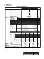
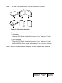
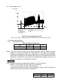
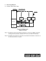
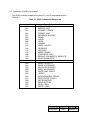
1
OEM Manual
Hard Disk Drive Specifications
Ultrastar 15K73-73/36
(SCSI)
Models
Models
Models
Models
HUS157373EL3600
HUS157336EL3600
HUS157373EL3800
HUS157336EL3800
:(73GB/68pin)
:(36GB/68pin)
:(73GB/80pin)
:(36GB/80pin)
Read and follow all instructions and cautions for safety described
in this document before using the drive.
It is recommended that this manual is kept at a proper location
for quick reference.
Hitachi Global Storage Technologies
© 2003, Hitachi Global Storage Technologies. All Rights Reserved.
Drawing No. Sheet No. Revision 5
K6602906
1/46
2003/6/12
REVISION CONTROL
Remarks
AD: Addition , CH: Change ,CR: Correction ,DL: Deletion
Rev.
Date
Signature
Page
Description
0 2002/11/5 DWN : O,Suzuki
All
First Issuance
1
2003/1/17
2
2003/2/7
3
2003/3/28
4
2003/4/1
5
2003/6/12
CHKD:
APPD:
DWN : O,Suzuki
CHKD:
APPD:
-
DWN : O,Suzuki
CHKD:
APPD:
DWN : O,Suzuki
CHKD:
APPD:
DWN : O,Suzuki
CHKD: T,Okazaki
APPD: K,Tsuneta
DWN : O,Suzuki
CHKD: T,Okazaki
APPD: K,Tsuneta
3-5
11
27
1
11
Remarks
Safety cautions were moved before
table of contents.
Seek time, Power requirement
Power dissipation
9.3 Storage
Model Name
Acoustic noise
CH
CH
CH
CR
CR
11
Seek time, Power requirement
Power dissipation
CH
11
Power requirement, Power dissipation
Energy consumption rate
Power measurement (Operating)
Regulations related to electromagnetic compatibility
CH
Note5_2. Surface temperature
CH
14
9
12
CH
CH
Drawing No. Sheet No. Revision 5
K6602906
2/46
2003/6/12
To use this product safely
Read and follow all instructions and cautions described in this chapter before using the
drive. It is recommended that this manual is kept at a proper location for quick reference.
The description related to safety in this chapter may be changed without notice.
Influence for environment
Although this product emits electro-magnetic field, it will be found to be in compliance with
the EMI regulations such as VCCI class B, FCC Part 15 class B. However, anything other
than this product, such as an interface cable, is excluded. Therefore, the following cases
require a system side improvement.
(1) Disturbance of operations of other products or equipment
(2) Disturbance caused by other product, such as cabling, to operations of other products
or equipment.
Do not change the condition of the drive, excluding the change admitted by Hitachi.
Violating above-mentioned precautions will void any warranties of the HDD.
Please read and understand the following explanation for safety.
General cautions for safety
0.1.1
When handling the drive, follow all instructions and cautions described in this
manual and the packing specification manual.
0.1.2
The safety instructions in this manual are thoroughly considered, but unexpected
situations can occur. Not only follow the instructions in this manual, but also be
careful for the safety by yourself.
0.1.3
Do not convert or change the drive. Convert or change of the drive will void any
warranties.
0.1.4
It is customer’s responsibility to assure the actual system in which the drive is
installed meets the appropriate safety regulation. However the drive itself is found
to be compliance with the following standards:
UL 1950 3rd Edition
CAN/CSA C22.2-M95
IEC60950: 1991
EN60950: 1992
FCC Part15 Class B, VCCI Class B
EN55022: 1998, Class B (CE Mark)
AS/NZS 3548: 1995, Class B (C-tick)
CNS13438/C6357, Class B (BSMI)
RRL mark for Korean EMC
Headline of safety caution
Safety instructions and cautions are indicated as the following head line which means as
follows.
This symbol indicates that potential danger may exist which may
Caution
cause slight or medium grade bodily injury if safety instructions are not
followed.
This symbol indicates that potential danger may exist which may
Caution
cause damage to the product or to the neighboring property if safety
instructions are not followed.
Drawing No. Sheet No. Revision 5
K6602906
3/46
2003/6/12
To use this product safely (Continued)
Followings are the cautions and contents described in this manual.
Caution :
Items of indicating
- Safety cautions for this product
Page 4
Items of indicating Caution
:
- Safety cautions for this product
- Spindle Start and Stop
- Mounting of the drive
- Reliability temperature
- Precautions for handling
Page 4-5
Page 16
Page 24
Page 26
Page 27
Safety cautions for this product
Caution
0.2.1
0.2.2
0.2.3
0.2.4
This product is not authorized for use in life support devices or other applications
which pose a significant risk of personal injury.
Handle the drive with care not to suffer bodily injury caused by hitting the edge of
the frame or accidental dropping of the drive.
Since the drive uses glass media for the disk platter, opening of HDA may cause
bodily injury. Warranty void in case of opened HDA or any broken HDA seals. Do
not open the HDA or break any HDA seals.
Temperature of the drive may become more than 50°C. Handle the drive carefully
not to get burned.
Caution
0.2.5
To prevent data from being lost due to an unexpected fatal error, data back up is
required.
0.2.6
If a foreign conductive substance (metallic powder, fluid, etc.) adheres to active
metal of the drive (Print pattern, component lead, etc. on Printed Circuit Board
(PCB)), it may cause catastrophic failures. Customer should protect the drive from
the above condition.
0.2.7
Improper insertion of connector or wrong jumper setting may cause catastrophic
failures. Referring to this manual prior to the connector insertion or jumper setting
can help insure correct insertion.
0.2.8
Follow the environmental conditions and power requirement described in this
manual. If violating these specifications, the drive failure may occur.
0.2.9
Protect the drive against Electro Static Discharge (ESD) during handling.
0.2.10 If storage period becomes long after unpacking, supply power to the drive and
rotate the disks 8 minutes or more. This operation shall be executed every 3
months.
Drawing No. Sheet No. Revision 5
K6602906
4/46
2003/6/12
To use this product safely (Continued)
Caution
0.2.11 Protect the drive against shocks with the corrugated board and cushioning
material provided by the manufacturer, or with Hitachi Approved containers.
0.2.12 When mounting the drive, use the size of screws and the torque recommended in
this manual. If non-recommended size of screws and torque are used, it may
cause catastrophic failures.
0.2.13 Do not press top cover and bottom PCB of the drive. It may cause catastrophic
failures.
0.2.14 Read and follow all instructions and cautions described on the top cover of the
drive, and in the chapter, Precautions for handling, in this manual.
0.2.15 In case of fluctuations in the DC power (spikes, momentary shut off, etc.), the data
being recorded or to be recorded from buffer memory are not assured.
0.2.16 If you find a smoke or a bad smell generating from the product, stop using it, turn
the power off, and see your sales contact.
0.2.17 Do not cover the breathing hole on the surface of the drive with use of a seal.
Warranty and Limited Liability
This product is sold with a limited warranty and specific remedies are available to the
original purchaser in the event the product fails to conform to the limited warranty. Hitachi’s
liability may be further limited in accordance with its sales contact.
In general, Hitachi shall not be responsible for product damages caused by natural
disasters, fire, static discharge, misuse, abuse, neglect, improper handling or installation,
unauthorized repair, alteration, or accident. In no event will Hitachi be liable for loss of data
stored on product.
Hitachi shall not be liable for any special, incidental or consequential damages, even if
informed of the possibility thereof in advance.
Please see your sales contact for a complete statement of warranty rights, remedies and
limitation of liability.
Drawing No. Sheet No. Revision 5
K6602906
5/46
2003/6/12
TABLE OF CONTENTS
Chapter
Page
To use this product safely. ................................................................................. 3
1 Features ............................................................................................................... 8
2 Standards and Related Documents.................................................................. 9
3 Description .......................................................................................................... 10
3.1
Characteristics...................................................................................... 10
3.2
Environmental conditions and reliability............................................. 11
4 DC power Interface............................................................................................. 15
4.1
DC Power Requirement....................................................................... 15
4.2
Power Supply Current .......................................................................... 16
4.3
Spindle Start and Stop......................................................................... 16
5 Connecting Methods........................................................................................... 18
6 SCSI Interface ..................................................................................................... 20
6.1
Summary of SCSI Controller ............................................................... 20
6.2
Summary of SCSI Commands............................................................ 22
7 Mounting and Handling ....................................................................................... 23
7.1
Orientations ........................................................................................... 23
7.2
Mounting of the drive ............................................................................ 24
7.3
Mounting dimensions ........................................................................... 25
7.4
Precautions on the off-line test or bench test..................................... 26
7.5
Cooling of the drive............................................................................... 26
7.6
Reliability temperature ......................................................................... 26
8 Precautions for handling..................................................................................... 27
8.1
Packing .................................................................................................. 27
8.2
Transportation....................................................................................... 27
8.3
Storage .................................................................................................. 27
8.4
Other Precautions ................................................................................. 28
9 Maintenance ......................................................................................................... 28
10 Physical interface................................................................................................ 29
10.1
Connector Specifications .................................................................... 29
10.2
Cable Specifications ............................................................................ 29
10.3
Connector Layout.................................................................................. 31
Drawing No. Sheet No. Revision 5
K6602906
6/46
2003/6/12
11 Pin assignment.................................................................................................... 33
11.1
SCSI Bus Connector C1...................................................................... 33
11.2
Other connectors................................................................................... 37
12 Jumper Socket setting........................................................................................ 39
12.1
Jumper connector layout ...................................................................... 39
12.2
Jumper socket setting .......................................................................... 41
12.3
Jumper socket part number................................................................. 46
12.4
Extension connector (for remote cable) ............................................. 46
Drawing No. Sheet No. Revision 5
K6602906
7/46
2003/6/12
1
Features
The Ultrastar 15K73 series uses high performance sputtered disks, GMR heads, and a
rotary type voice coil motor to drive the heads. These features provide high capacity, high
speed positioning and high reliability.
The Ultrastar 15K73 series uses a SCSI interface for data transfer.
Related ANSI Specifications are as follows.
ANSI X3.301-1997
(SCSI-3 Primary Commands)
X3T10/995D Rev 11a
(SCSI-3 Primary Commands)
X3T10/996D Rev 8c
(SCSI-3 Block Commands)
X3T10/1142D Rev 20a
(SCSI Parallel Interface-2)
X3T10/1236-D Rev 20
(SCSI Primary Commands-2)
X3T10/1302D Rev 14
(SCSI Parallel Interface-3)
X3T10/1416D Rev 3
(SCSI Primary Commands-3)
X3T10/1365D Rev 4
(SCSI Parallel Interface-4)
Interface specifications for the Ultrastar 15K73 are found in the companion manual:
" Hitachi 3.5 inch Magnetic Disk Drive Reference Manual for Ultrastar 15K73
(SCSI Interface Specification) ".
Product name
Table 1.1 Models
Model name
Interface type
Storage
capacity
(Formatted)
73.9GB
Ultrastar
15K73-73
HUS157373EL3600
Wide LVD (68pin-16bits)
Ultra320
Ultrastar
15K73-36
HUS157336EL3600
Wide LVD (68pin-16bits)
Ultra320
36.9GB
Ultrastar
15K73-73
HUS157373EL3800
SCA-2 LVD (80pin-16bits)
Ultra320
73.9GB
Ultrastar
15K73-36
HUS157336EL3800
SCA-2 LVD (80pin-16bits)
Ultra320
36.9GB
Note 1: This document may be changed without notice.
Drawing No. Sheet No. Revision 5
K6602906
8/46
2003/6/12
2
Standards and Related Documents
(a) Safety standards
It is the user’s responsibility to assure the actual system in which the drive is
installed meets the appropriate safety requirements. However, the drive was tested
to be in compliance with the following standards:
UL 1950 3rd Edition
CAN/ CSA C22.2-M95
IEC 60950: 1991
EN60950: 1992
(b) Regulations related to electro-magnetic compatibility
It is the user’s responsibility to assure the actual system in which the drive is
installed meets the appropriate EMI requirements. However the drive will be tested
using proper shielding and grounding to be in compliance with the following
regulations:
FCC Part 15, class B
VCCI class B
EN55022 class B
CNS13438,C6357 class B (BSMI)
AS/NZS 3548 class B (C-Tick)
RRL mark for Korean EMC
(c) Related Documents
(1) Hitachi 3.5 inch Magnetic Disk Drive Reference Manual for Ultrastar 15K73
(SCSI Interface Specification)
K6602924
(2) Packing Specification
K6601289
(3) Ultrastar 15K73-73 (SCSI) Design Verification Test Reports
K6602907
(4) Ultrastar 15K73-36 (SCSI) Design Verification Test Reports
K6602908
Drawing No. Sheet No. Revision 5
K6602906
9/46
2003/6/12
3 Description
3.1 Characteristics
Table 3.1 Characteristics
Item
Specifications
Ultrastar 15K73-73
Ultrastar 15K73-36
73.9
36.9
unit
GB
Configuration Storage capacity
(formatted) (see Note 1,2,13)
Bytes/sector (see Note 3)
512, 516, 520, 524, 528,1024
Bytes
Number of disks
5
3
Number of heads
10
5
Areal density
31.2
Gb/inch2
Recording method
MEEPRML
Performance Seek time
average
3.9 / 4.2
ms
read / write
full stroke
7.2 / 8
ms
(see Note 5)
1 track
0.4 / 0.5
ms
Average latency
1.99
ms
Rotational speed
15037
rpm
Data transfer rate (In drive)
684 – 960
Mb/s
Start time (see Note 5)
25
s
Data transfer
Single-Ended Asynchronous
5.0 max. MB/s
rate
Fast-5
10.0 max.
(Controller)
Fast-10
20.0 max.
Ultra (Fast-20)
40.0 max.
(see Note 4)
LVD
Ultra2 (Fast-40)
80.0 Max.
Ultra160 (Fast-80)
160.0 max.
Ultra320 (Fast-160)
320.0 max.
Buffer size
8M
Bytes
Typ.
3sigma
(Note5)
Power
12V Spin-up, peak
requirement 12V Seek, peak
12V Idle, ave.
5V R/W, peak
5V Read, ave.
5V Write, ave.
5V Idle, ave.
length x width x height
weight
+12V Idle / +5V Idle, (Average)
Physical
dimensions
Power
dissipation
Energy consumption rate (see Note 12)
Typ.
3sigma
(Note 5)
2.20
2.64
0.75
1.54
1.45
1.20
0.60
2.44
2.20
2.85
2.45
0.81
0.57
1.65
1.54
1.56
1.45
1.28
1.20
0.64
0.60
146.0x101.6x25.4
2.44
2.65
0.62
1.65
1.56
1.28
0.64
0.69
12.0
0.67
9.8
0.162
0.266
Drawing No. Sheet No. Revision 5
K6602906
10/46
2003/6/12
A
A
A
A
A
A
A
mm
kg
W
3.2 Environmental conditions and reliability
Table 3.2 Environmental conditions and reliability
Item
Environmental
conditions
Ultrastar 15K73-73
operating
Temperature
non-operating
storage/shipping
Temperature gradient
Humidity
operating
non-operating
Wet bulb temperature
Atmosphere
Altitude
operating
non-operating
Magnetic field
Shock and
Vibration
operating
vibration
(see Note 6)
non-operating
Shock
operating
(see Note 7)
non-operating
Acoustic noise
Reliability
Acoustic noise (see Note 8)
Data Reliability (see Note 9)
Seek error rate (see Note 9)
(see Note 10)
Life
Ultrastar 15K73-36
5 to 55°C
-40 to 70°C
-40 to 70°C
20°C per hour maximum
5 to 90%RH
5 to 90%RH
29°C maximum (non condensing)
No corrosive gas, saline atmosphere
or organic-metal compound
(Example. organic silicon,organic tin)
-300 to 3,000 m
-300 to 12,000 m
400 micro Tesla maximum
9.8 m/s2(1.0G) maximum
49 m/s2(5.0G) maximum
147 m/s2(15G) maximum [11ms]
735 m/s2(75G) maximum [11ms]
2450m/s2(250G) maximum [2ms]
3.7 bel average
3.6 bel average
Recoverable error:
10 error in 1012bits read
Non-recoverable error: 1 error in 1014bits read
10 errors in 108 seeks
5 years (Surface temperature of HDA is 45°C or less)
Life of the drive does not change in the case that the
drive is used intermittently. (See section 8.6)
MTBF (see Note 11)
Expected 1,200,000 hours
Drawing No. Sheet No. Revision 5
K6602906
11/46
2003/6/12
Note 1. Storage capacity does not include spare sector and spare cylinder.
Note 2. This is the value in the case that the drive is formatted to 512 Bytes/sector.
(1 gigabyte shows 1x109 bytes on this document.)
Note 3. Ultrastar 15K73 is formatted to 512 Bytes/sector as the default.
If non-512 Bytes/sector is required, customer can change it by re-format
of the drive.
Note 4. Data transfer rate is degraded with cable or host condition or electrical noise.
Note 5. These specifications are typical under the following conditions:
1. Voltage is 5.0V/12.0V as measured on the edge of drive connector.
2. Surface temperature of HDA is 40°C.
If SCSI commands are issued during start-up (like TEST UNIT READY or
REQUEST SENSE) in less than 10 ms intervals, then the start-up time may be
extended.
Note 6. The disk drive orientation for vibration test is shown below.
Figure 3.1 Vibration test direction
Test conditions on vibration test are as follows.
(1) Operating
Acceleration frequency : 5 to 400 Hz,
Acceleration level : 9.8m/s2(1.0G)
Sweep rate : 0.5 octave / minute
Test cycle : 1 turn
(2) Non-operating
Acceleration frequency: 5 to 22 Hz, Maximum displacement: 2.56mm
Acceleration frequency: 22 to 400 Hz, Acceleration level: 49m/s2(5.0G)
Sweep rate: 0.5 octave / minute
Test cycle: 1 turn
Drawing No. Sheet No. Revision 5
K6602906
12/46
2003/6/12
Note 7. The disk drive orientation for shock test is shown in Figure 4.2.
Figure 3.2 Shock test direction
Test conditions on shock test are as follows.
(1) Operating
147m/s2(15G) (Shock mode: half sine wave 11 ms, Test cycle: 5 times)
(2) Non-operating
735m/s2(75G) (Shock mode: half sine wave 11 ms, Test cycle: 5 times)
2450m/s2(250G) (Shock mode: half sine wave 2 ms, Test cycle: 5 times)
Note 8. Acoustic noise is measured except for the start, stop and seek operations.
Drawing No. Sheet No. Revision 5
K6602906
13/46
2003/6/12
Note 9. Recoverable error is measured at the nominal condition with voltage,
temperature and default error recovery parameters.
Note 10. The drive should be mounted properly (see section 8).
Note 11. MTBF represents a prediction of performance based upon a large
statistical sample calculated in accordance with Hitachi's standard
procedures.
Hitachi does not warrant that the predicted MTBF is representative of any
particular unit or group of units comprising a customer base. The actual
failure rates will vary from unit to unit. Surface temperature of HDA is
50°C or less.
A failure defined by MTBF calculation is any event that requires repair or
replacement of HDD.
Note 12. Total idle mode power (W) / Total formatted capacity (GB)
Note 13. When the Ultrastar 15K73-73 is formatted to 512 Bytes/sector,
the maximum Logical Block Address is (89B88FF)h.
When the Ultrastar 15K73-36 is formatted to 512 Bytes/sector,
the maximum Logical Block Address is (44DC47F)h.
Note 14. Power measurement values in operating (Random Seek/ Read/ Write) case are
shown in Table 4.3.
Table 3.3 Power measurement (Operating)
Unit:(W)
Ultrastar 15K73-73
Ultrastar 15K73-36
30 IOs per second
13.2
10.9
60 IOs per second
14.5
12.1
90 IOs per second
16.0
13.6
(Measurement conditions:Random Read/Write,Block Length=8,Cache=off)
Drawing No. Sheet No. Revision 5
K6602906
14/46
2003/6/12
4
DC power Interface
4.1 DC Power Requirement
The drives are operated on DC power (+5V, +12V) only.
No power sequencing is required.
The +5 and +12 Volts can be applied in any order.
Table 4.1 DC Power Requirement
Power supply
Voltage tolerance
Allowed ripple and noise
+5V DC
5.0V +/-5%
Less than 150mVp-p (0 - 100kHz)
Less than 100mVp-p (100kHz - 10MHz)
+12V DC
12.0V +/-5%
Less than 150mVp-p (0 - 100kHz)
Less than 100mVp-p (100kHz - 10MHz)
Note 1. Voltage tolerance is measured at the DC power connector on the PCB.
The ripple current occurs during the motor start-up and seek.
Appropriate size of the DC Power cable is recommended to reduce the above
ripple and noise.
Note 2. In case of fluctuations in the DC power (spikes, momentary shut off, etc.), the
data being recorded or to be recorded from buffer memory are not assured.
Drawing No. Sheet No. Revision 5
K6602906
15/46
2003/6/12
4.2 Power supply current
+12V Current
[A]
3.0
Peak
2.0
1.0
0
0
2
4
6
8
10
12
14
16
18
20
Time [s]
T0
T1
T0-T1: Power up
T1-T2: Spin-up
T2-T3: Servo initialize
T3-T4: Upload Code etc.
T1-T4: Start up
T2 T3
T4
T0 : Power on
T1 : Accept start unit command or Auto Spin-up
T4 :Ready
Fig 4.1 Current transition for +12V
Note: A retry Spin-up operation may be attempted during the Start up process.
4.3 Spindle Start and Stop
4.3.1 Start and Stop Time
Table 4.2 Start and Stop time
Item
Typical
Start
25
Note 1
Stop
25
Note 2
unit
s
s
Note 1. Start time means that the time of becoming ready, after DC power has been
applied in the case of Enable Auto Start mode, or after Start Unit command
(immed=0) has accepted in other case. If internal retry is executed during the Startup operation, the Start time may exceed typical value. It is recommended to have 60
seconds for the Start time. In the case of a spindle start-up failure, the time of an
internal retry operation is 130 seconds maximum.
Caution
Note 2. Beginning of stop time is basically decided by +12v DC power off.
In case of +5v DC power off only, stop time is 65sec(typ).
Do not move the drive until motor stop completely.
Stop time means that the time to stop the spindle rotation, after DC power has
been shut off, or after stop operation has started.
Drawing No. Sheet No. Revision 5
K6602906
16/46
2003/6/12
4.3.2 Spindle Start Selection
When multiple disk drives are connected to the same power supply and turned on
simultaneously, a large current will be required at power up.
In the above case, it is recommended to turn the motors on one by one at intervals in
order to minimize 12V line current.
This can be done according to the following 3 jumper pin configurations in the case of
NW drive:
1. If Disable Auto Start mode is set (C3:9-10 installed);
(1) Use a spindle start command for each drive, issuing it to the next drive after
receiving the previous drive’s Ready condition.
or
(2) Use the spindle start command for each drive, issuing it at intervals of more than
10 seconds.
2. If Enable Auto Start mode is set (C3:9-10 removed) and Spindle Start at Power On
is set (C3:13-14 removed);
Manually power on drives at intervals of more than 10 seconds.
3. If Enable Auto Start mode is set (C3:9-10 removed) and Delayed Start is set (C3:1314 installed);
Upon power on condition, the drives will automatically spin up in 10 second intervals
according to their SCSI ID. (The drive with the lowest SCSI ID will start first.)
In the case that their SCSI ID are more than 7, the drives will automatically spin up in
10 second intervals according to the numbers of (SCSI ID minus 8).
Note 1 The Delayed Start setting and the Auto Start setting can be done by commands
from host via SCSI bus connector (C1) in the case of NC drive.
Drawing No. Sheet No. Revision 5
K6602906
17/46
2003/6/12
5
Connecting Methods
5.1 Interface Cable (Daisy Chain)
Terminator
SCSI interface cable
Terminator
SCSI bus
Ultrastar
Ultrastar
Ultrastar
15K73
15K73
15K73
DC power
power supply cable
GND
Figure 5.1 Cabling layout
(WIDE LVD drive)
Note 1. The SCSI bus can accommodate a maximum of 16 units on a WIDE (16-bit) bus,
including the host processor, Ultrastar 15K73 units, and other SCSI devices.
Note 2. The WIDE LVD and SCA-2 LVD drives do not have the terminator on the drive, so
an external terminator is required.
Drawing No. Sheet No. Revision 5
K6602906
18/46
2003/6/12
5.2 Low voltage differential (LVD) mode
The NW and NC drives have two different transceivers to allow customer to use it in
traditional systems which may use single-ended drivers and receivers, or to use it in
low voltage differential (LVD) systems which use LVD drivers and receivers.
Their I/O circuits are selectable using the I/O "DIFFSENS" line. When the I/O
"DIFFSENS" line is between -0.35V and +0.5V, the drive interface circuits operate
single-ended. When "DIFFSENS" is between +0.7V and +1.9V, the drive interface
circuits operate LVD.
Customer can configure the drive to switch between single-ended and LVD modes
using the I/O "DIFFSENS" line, or force it to operate in single-ended mode only as
described later in this document.
Note 1: To operate at LVD mode, all devices on the same bus must be running in LVD
mode. If you add any single-ended device to a bus that is operating in LVD mode,
all devices drop back to operating in single-ended mode. This eliminates the
possibility of reaching Ultra-2 SCSI transfer rates.
Note 2: Do not mix LVD drives on the same daisy chain with devices having high voltage
differential (HVD) interface circuits.
Drawing No. Sheet No. Revision 5
K6602906
19/46
2003/6/12
6 SCSI Interface
6.1 Summary of SCSI Controller
The Ultrastar 15K73 SCSI controller interfaces between the drive and the host
computer with the Small Computer System Interface (SCSI).
(1) ANSI standard
The controller supports the SCSI interface that conforms to the ANSI specifications
shown in section 2.
(2) Compact design
The controller is embedded within the disk drive.
(3) Fast data transfer rate
The controller can transfer data via asynchronous mode, Fast-5 synchronous mode,
Fast-10 synchronous mode and Ultra (Fast-20) synchronous mode.
The controller can transfer data via Ultra2 (Fast-40) synchronous mode and Ultra160
(Fast-80) synchronous mode and Ultra320 (Fast-160) synchronous mode, as well as
above-mentioned transfer mode.
(4) FIFO buffer
The Ultrastar 15K73 SCSI controller has 8M bytes of FIFO buffer. This data buffering
feature prevents the SCSI controller from delay during the reconnect process and
reduces the latency time that is generated by the difference of the data transfer rate
between media and host.
(5) Automatic error retry
The controller automatically retries whenever the disk drive encounters errors.
(6) Automatic error corrections
The controller uses 40 bytes ECC and On-The-Fly to automatically correct read
errors, without latent rotational time.
(7) Parameter save feature
The controller saves the controller/device parameters (MODE SELECT parameters)
specified by the host onto the disk drive. The parameters are automatically restored at
power-on time.
Drawing No. Sheet No. Revision 5
K6602906
20/46
2003/6/12
(8) Tagged Command Queuing
A maximum of 110 commands can be enqueued to this drive. The drive does not have
to connect and disconnect to the host controller even if the SCSI command has been
issued successively, so the overhead time of the SCSI bus can be reduced.
(9) S.M.A.R.T. (Self - Monitoring, Analysis and Reporting Technology)
This function helps predict a failure related to the degradation of the disk drive itself.
For users seeking to use the drive as long as possible, S.M.A.R.T. can be used to
predict when failure might occur. The user can use this information to back-up the data
before failure.
The S.M.A.R.T. report is written on the disk at regular intervals that are not based on
drive usage.
(10) Automatic Read Reallocation
When an error is detected on reading the data, this function automatically assigns an
alternate sector in place of the defective sector and stores the data on the alternated
sector.
(11) Write Cache
The controller can return a completion of a WRITE command with a GOOD status after
receiving the data from the host but before writing the data from its buffer to the media.
The Deferred Error function reports an Disk Access Error to the host computer if an
error occurs when the data are being stored on the disk medium after the GOOD status
was already returned. In this case, any data still in the buffer (not yet written to the
media) is not assured.
(12) Log Save
Diagnostic information is written on the disk at regular intervals that are not based on
drive usage.
Drawing No. Sheet No. Revision 5
K6602906
21/46
2003/6/12
6.2 Summary of SCSI Commands
The SCSI controller supports the group 0,1, and 2 commands listed in
Table 6.1
Table 6.1 SCSI Commands Supported
Operation Code
00h
01h
03h
04h
07h
08h
0Ah
0Bh
12h
15h
16h
17h
1Ah
1Bh
1Ch
1Dh
Operation Code
25h
28h
2Ah
2Bh
2Eh
2Fh
35h
37h
3Bh
3Ch
3Eh
3Fh
Group 0 Command Name
TEST UNIT READY
REZERO UNIT
REQUEST SENSE
FORMAT UNIT
REASSIGN BLOCKS
READ
WRITE
SEEK
INQUIRY
MODE SELECT
RESERVE
RELEASE
MODE SENSE
START/STOP UNIT
RECEIVE DIAGNOSTIC RESULTS
SEND DIAGNOSTIC
Group 1 Command Name
READ CAPACITY
READ (EXTENDED)
WRITE (EXTENDED)
SEEK (EXTENDED)
WRITE AND VERIFY
VERIFY
SYNCHRONIZED CACHE
READ DEFECT DATA
WRITE BUFFER
READ BUFFER
READ LONG
WRITE LONG
Drawing No. Sheet No. Revision 5
K6602906
22/46
2003/6/12
Table 6.1 SCSI Commands Supported (Continued)
Operation Code
41h
4Ch
4Dh
55h
56h
57h
5Ah
5Eh
5Fh
Operation Code
B7h
A0h
7
Group 2 Command Name
WRITE SAME
LOG SELECT
LOG SENSE
MODE SELECT (10)
RESERVE (10)
RELEASE (10)
MODE SENSE (10)
PERSISTENT RESERVE IN
PERSISTENT RESERVE OUT
Group 5 Command Name
READ DEFECT DATA (12)
REPORT LUNS
Mounting and Handling
7.1 Orientations
The following orientations are acceptable.
Horizontal (1)
Vertical (1)
Vertical (3)
Horizontal (2)
Vertical (2)
Vertical (4)
Fig. 7.1 Orientations
Drawing No. Sheet No. Revision 5
K6602906
23/46
2003/6/12
Caution
7.2 Mounting of the drive
1. Mount the drive with four 6-32 UNC screws. (Screw's torque : 0.588 to 0.784 N·m)
2. Mounting holes (A1,A2,B1,B2,B3) are available for mounting.(See figure 8.3)
It is recommended that the 4 holes, (A1,A2 or B1,B3 on figure 8.3), be used for mounting to
keep the proper space between mounting holes.
3. Maximum penetration of the screw is 3.8 mm.
4. Keep a clearance of 3 millimeters from the PCB parts side and the HDA's upper surface for
proper cooling air ventilation. (See figure 8.2)
5. The mounting chassis’s weight shall be more than 2 kg, and the stiffness of mounting
chassis shall be more than 196,000 N/m. The stiffness of 4 mounting points shall not be unbalanced.
6. The HDA enclosure is connected to the DC ground on PCB in HDA electrically.
If electrical insulation of the HDA is preferred when it is mounted to the mounting chassis,
insert an insulator between the HDA enclosure and the mounting chassis.
Good case
Bad case
HDA upper surface
spacer
PCB parts side
Figure 7.2 Example for mounting
Drawing No. Sheet No. Revision 5
K6602906
24/46
2003/6/12
7.3 Mounting dimensions
F
G
H
J
K
L
B
D
E
Dimension
A
B
C
D
E
F
G
H
J
K
L
A
C
mm
101.6±0.25
95.25±0.25
3.18±0.25
41.28±0.5
44.45±0.25
147 max.
101.6±0.25
28.5±0.5
41.6±0.25
26.1 max.
6.35±0.25
Figure 7.3 Layout of Mounting holes
Drawing No. Sheet No. Revision 5
K6602906
25/46
2003/6/12
7.4 Precautions on the off-line test or bench test
When the off-line test or bench test is performed the drive should be tightly fixed
and cooled. The set-up should be similar to the actual system configuration.
7.5 Cooling of the drive
Keep the drive (HDA and PCB) cool by using a FAN. Reliability and life of the drive
increases as the temperature is lower.
Caution
7.6 Reliability temperature
The temperature measurement points and temperature limits are shown below.
1. The maximum temperature assures the data reliability, seek error rate, and must not
be exceeded.
2. The reliability temperature maintains the MTBF of the drive and must not be
exceeded in order to ensure its reliability. MTBF is also based on a nominal voltage
condition.
3. The maximum temperature of HDA includes momentary temperature rise. Average
temperature of HDA has to be less than this temperature.
Table 7.1 Temperature Limits (unit: °C)
Measurement points
HDA(top) HDA(bottom)
IC(RW)
IC(MPU)
Maximum temperature
65
65
85
85
Reliability temperature
50
50
70
70
HDA(top)
IC(RW) HDA(bottom)
Breathing hole
IC(MPU)
Figure 7.4 Temperature Measurement Points
Drawing No. Sheet No. Revision 5
K6602906
26/46
2003/6/12
Caution
8
Precautions for handling
The drive is sensitive to shock, vibration, over voltage, temperature, humidity,
corrosive gas, magnetic force and electrostatic discharge.
If these forces contact the electrical or mechanical components (magnetic heads,
magnetic disks), the drive will break down, degrade, or storage data will be lost.
The following handling guidelines are mandatory.
(1) Handle the drive on the appropriate cushion (for example, anti-static pad with
thickness of 10mm or more) to prevent from shock and vibration.
(2) Handle the drive with a wrist band, an anti-static mat, or without direct touch of the
hands to the PCB in order to prevent static electricity discharge.
(3) Handle the drive in an environment (Temperature, Moisture, Corrosive gas), which
follows the drive specification and prevents unforeseen complications.
8.1 Packing
After cleaning the drive, pack it in the following manner to protect it from moisture.
(1) Put the drive in an electro-static shielding bag with desiccant.
(2) Packing materials, i.e. electro-static shielding bag, cardboard box, cushion, etc.,
should not contain corrosive gas, saline or organic-metal compound. (Example
organic silicon, organic tin)
(3) If the package has no damage after unpacking, reserve it for storage or
Transportation of the drive.
But 20-unit packing material is suitable for only 20 units packing.
When less than 19 units, it is recommended to use the 5-unit packing material.
5-units packing material covers the quantity from 1 to 5.
8.2 Transportation
(1) Pack the drive so as to maintain above-mentioned environmental conditions during
transportation. (Refer to section 4.2)
(2) When you take the drive out of the packing case and carry it on a hand truck, lay it
on cushioning material (for example, urethane foam cushioning with a thickness of
10mm or more).
8.3 Storage
When storing, pack the drive to protect it against moisture. (Refer to section 4.2)
In case that storage period becomes long, exchange a desiccant and repack.
This operation shall be executed every 3 months.
Drawing No. Sheet No. Revision 5
K6602906
27/46
2003/6/12
8.4 Other Precautions
8.4.1 Do not loosen the screws or disassemble the drive.
8.4.2 Do not remove the PCB from the drive or swap the PCB with other drives.
8.4.3 Do not solder the wire or other parts on the PCB, or reconstruct the PCB.
8.4.4 Do not remove the sealing tape or label on the HDA.
8.4.5 Turn off the power before removing or installing the DC power cable and
SCSI interface cable. Turn off the power before removing or installing the jumper.
8.4.6 Remove the DC power and SCSI interface connectors carefully in order
not to damage the contact pins and the connector housing.
8.4.7 Do not move the drive when the disks are rotating or while the power is
on or for 20 seconds after the power has been turned off.
9.4.8 Do not cover the breathing hole on the surface of the drive with use of a seal. (The
position of the breathing hole is shown in Figure 8.4.)
9
Maintenance
9.1 The HDD itself is maintenance free and there are no individual parts that require
maintenance. If maintenance for the HDD is required, the entire product will need to
be serviced, since it can not be divided into parts. System maintenance should be
executed by the host system.
9.2 The supplier will repair or exchange the product due to malfunction covered under
the warranty. The warranty and service will be agreed upon between the customer
and the supplier. The supplier is neither liable or obligated to service any product
due to carelessness or mishandling of product.
9.3 Even if the drive fault occurs during the In-warranty period, the supplier will repair or
replace the drive but will not be liable for any expenses of disk drive installation or
detachment to or from system. (This includes data back up, data copy, etc.)
Drawing No. Sheet No. Revision 5
K6602906
28/46
2003/6/12
10 Physical interface
10.1 Connector Specifications
Use the mating connectors which are electrically and mechanically compatible.
The following part numbers indicate the mating connectors.
Table 10.1 Interface connectors
Interface
WIDE LVD
Name
SCSI interface connector
Manufacturer
786090-7
AMP
DHJ-PAC68-2AN
DDK
Pin:61314-4
AMP
Housing:1-480424-0
AMP
SCSI interface connector
787311-1
AMP
with DC power connector
787565-1
AMP
HD2-PA080-S11
DDK
DC power connector
SCA-2 LVD
Part number
10.2 Cable Specifications
(1) SCSI Interface Cable
Use interface cables that meet the ANSI SCSI guideline.
The total cable length must be within the maximum cable length in case multiple drives
are daisy chained. Specifications of maximum cable length are shown in Table 10.2
and Table 10.3.
The length of a cable connected between SCSI devices must be a minimum of
12 cm. (The stub length of the drive: 4 cm)
If an external cable the stub length of which becomes long is connected
to the devices, the cable length between the devices must be a minimum of
(external stub length + 4 cm) x 3.
If data are transferred by Ultra SCSI (Fast-20) mode, Ultra2 SCSI (Fast-40) mode,
Ultra160 SCSI (Fast-80) mode or Ultra320 SCSI (Fast-160) mode, check that the
interface reflection noise does not influence the motion of the drive in the actual user’s
system.
Drawing No. Sheet No. Revision 5
K6602906
29/46
2003/6/12
(2) DC Power Supply Cable
The DC power cable should be as short as possible to minimize voltage drop.
Table 10.2 Interface cable (WIDE, Single-ended mode)
Cable Type
SCSI interface
Flat Ribbon or
Twisted Pair
DC power supply
AWG#20
Maximum cable length
Fast-5
Fast-10
Ultra (Fast 20)
6m
3m
3m (4 units max.) or
(16 units max.)
(16 units max.)
1.5m (8 units max.)
3m
Table 10.3 Interface cable (WIDE, LVD mode)
Cable Type
Maximum cable length
Ultra2 (Fast-40), Ultra160 (Fast-80) , Ultra320 (Fast-160)
SCSI interface
Flat Ribbon or
12m (16 units max.)
Twisted Pair
DC power supply
AWG#20
3m
Shield the cables as necessary to improve the interface noise immunity, especially if
the cables run close to noise generating devices or exit the frame or chassis.
Drawing No. Sheet No. Revision 5
K6602906
30/46
2003/6/12
10.3 Connector Layout
WIDE LVD drive
SCSI Bus Connector C1
Auxiliary Connector C4
Power Connector C2
Figure 10.1 Connector Layout (WIDE LVD drive)
C2-1 : 12V
C2-2 : GND (12V Return)
C2-3 : GND (5V Return)
C2-4 : 5V
34
68
C1
1
11
35
12
C4
C2
1
2
4
3
2
1
Figure 10.2 Connector view
Note: The SCSI ID setting is to be set via the C3 connector (not by C4) normally.
In case the SCSI ID setting is done by remote switch via the C4 connector and
remote cable, remove all Jumper Sockets from the C3 connector to avoid SCSI ID
control conflicts.
Drawing No. Sheet No. Revision 5
K6602906
31/46
2003/6/12
SCA-2 LVD drive
N P
D
M
W
L
Dimension
mm
Dimension
mm
H
26.1 max.
W
101.6±0.25
D
6.35±0.25
L
(58)
N
(7)
M
50.8±0.5
P
4.6±0.5
Figure 10.3 Connector Layout (SCA-2 LVD drive)
41
C1
80
PCB parts side
1
40
Figure 10.4 Connector view
Drawing No. Sheet No. Revision 5
K6602906
32/46
2003/6/12
H
11
Pin assignment
11.1 SCSI Bus Connector C1
Table 11.1 Pin assignment of SCSI Bus Connector C1
(WIDE, Single-ended mode)
Signal Name Connector
Cable
Connector Signal Name
contact
conductor
contact
No.
No.
No.
GND
1
1
2
35
-DB(12)
GND
2
3
4
36
-DB(13)
GND
3
5
6
37
-DB(14)
GND
4
7
8
38
-DB(15)
GND
5
9
10
39
-DB(P1)
GND
6
11
12
40
-DB(0)
GND
7
13
14
41
-DB(1)
GND
8
15
16
42
-DB(2)
GND
9
17
18
43
-DB(3)
GND
10
19
20
44
-DB(4)
GND
11
21
22
45
-DB(5)
GND
12
23
24
46
-DB(6)
GND
13
25
26
47
-DB(7)
GND
14
27
28
48
-DB(P0)
GND
15
29
30
49
GND
DIFFSENS
16
31
32
50
GND
TERMPWR
17
33
34
51
TERMPWR
TERMPWR
18
35
36
52
TERMPWR
Reserved
19
37
38
53
Reserved
GND
20
39
40
54
GND
GND
21
41
42
55
-ATN
GND
22
43
44
56
GND
GND
23
45
46
57
-BSY
GND
24
47
48
58
-ACK
GND
25
49
50
59
-RST
GND
26
51
52
60
-MSG
GND
27
53
54
61
-SEL
GND
28
55
56
62
-C/D
GND
29
57
58
63
-REQ
GND
30
59
60
64
-I/O
GND
31
61
62
65
-DB(8)
GND
32
63
64
66
-DB(9)
GND
33
65
66
67
-DB(10)
GND
34
67
68
68
-DB(11)
Drawing No. Sheet No. Revision 5
K6602906
33/46
2003/6/12
Table 11.2 Pin assignment of SCSI Bus Connector C1 (WIDE, LVD mode)
Signal Name Connector
contact
No.
+DB(12)
1
+DB(13)
2
+DB(14)
3
+DB(15)
4
+DB(P1)
5
+DB(0)
6
+DB(1)
7
+DB(2)
8
+DB(3)
9
+DB(4)
10
+DB(5)
11
+DB(6)
12
+DB(7)
13
+DB(P0)
14
GND
15
DIFFSENS
16
TERMPWR
17
TERMPWR
18
Reserved
19
GND
20
+ATN
21
GND
22
+BSY
23
+ACK
24
+RST
25
+MSG
26
+SEL
27
+C/D
28
+REQ
29
+I/O
30
+DB(8)
31
+DB(9)
32
+DB(10)
33
+DB(11)
34
Cable
conductor
No.
1
3
5
7
9
11
13
15
17
19
21
23
25
27
29
31
33
35
37
39
41
43
45
47
49
51
53
55
57
59
61
63
65
67
2
4
6
8
10
12
14
16
18
20
22
24
26
28
30
32
34
36
38
40
42
44
46
48
50
52
54
56
58
60
62
64
66
68
Connector Signal Name
contact
No.
35
-DB(12)
36
-DB(13)
37
-DB(14)
38
-DB(15)
39
-DB(P1)
40
-DB(0)
41
-DB(1)
42
-DB(2)
43
-DB(3)
44
-DB(4)
45
-DB(5)
46
-DB(6)
47
-DB(7)
48
-DB(P0)
49
GND
50
GND
51
TERMPWR
52
TERMPWR
53
Reserved
54
GND
55
-ATN
56
GND
57
-BSY
58
-ACK
59
-RST
60
-MSG
61
-SEL
62
-C/D
63
-REQ
64
-I/O
65
-DB(8)
66
-DB(9)
67
-DB(10)
68
-DB(11)
Drawing No. Sheet No. Revision 5
K6602906
34/46
2003/6/12
Table 11.3 Pin assignment of SCSI Bus Connector C1
(SCA-2, Single-ended mode)
Signal Name
12V
12V
12V
12V
Open
Open
-DB(11)
-DB(10)
-DB(9)
-DB(8)
-I/O
-REQ
-C/D
-SEL
-MSG
-RST
-ACK
-BSY
-ATN
-DB(P0)
-DB(7)
-DB(6)
-DB(5)
-DB(4)
-DB(3)
-DB(2)
-DB(1)
-DB(0)
-DB(P1)
-DB(15)
-DB(14)
-DB(13)
-DB(12)
5V
5V
5V
Reserved
AUTO START (Note 1)
-ID0 (Note 1)
-ID2 (Note 1)
Connector contact No.
1
41
2
42
3
43
4
44
5
45
6
46
7
47
8
48
9
49
10
50
11
51
12
52
13
53
14
54
15
55
16
56
17
57
18
58
19
59
20
60
21
61
22
62
23
63
24
64
25
65
26
66
27
67
28
68
29
69
30
70
31
71
32
72
33
73
34
74
35
75
36
76
37
77
38
78
39
79
40
80
Signal Name
GND(12V Return)
GND(12V Return)
GND(12V Return)
MATED1 (Note 2)
Open
DIFFSENS
GND
GND
GND
GND
GND
GND
GND
GND
GND
GND
GND
GND
GND
GND
GND
GND
GND
GND
GND
GND
GND
GND
GND
GND
GND
GND
GND
MATED2 (Note 2)
GND(5V Return)
GND(5V Return)
LED(with 0 ohm)
-DELAY START (Note 1)
-ID1 (Note 1)
-ID3 (Note 1)
Note 1 When this signal is held to ground, it is regarded as LOW. When this signal is open,
it is regarded as HIGH. It can be driven by open collector driver.
Do not pull up this signal.
Note 2 The MATED2 signal is tied to ground, and the MATED1 signal is pulled up to HIGH
level in the drive. When the drive detects the MATED1 signal is held to LOW, the
drive regards the connection has completed. When the drive detects the MATED1
signal is held to HIGH, it regards the connection is incomplete.
Drawing No. Sheet No. Revision 5
K6602906
35/46
2003/6/12
Table 11.4 Pin assignment of SCSI Bus Connector C1 (SCA-2, LVD mode)
Signal Name
12V
12V
12V
12V
Open
Open
-DB(11)
-DB(10)
-DB(9)
-DB(8)
-I/O
-REQ
-C/D
-SEL
-MSG
-RST
-ACK
-BSY
-ATN
-DB(P0)
-DB(7)
-DB(6)
-DB(5)
-DB(4)
-DB(3)
-DB(2)
-DB(1)
-DB(0)
-DB(P1)
-DB(15)
-DB(14)
-DB(13)
-DB(12)
5V
5V
5V
Reserved
AUTO START (Note 1)
-ID0 (Note 1)
-ID2 (Note 1)
Connector contact No.
1
41
2
42
3
43
4
44
5
45
6
46
7
47
8
48
9
49
10
50
11
51
12
52
13
53
14
54
15
55
16
56
17
57
18
58
19
59
20
60
21
61
22
62
23
63
24
64
25
65
26
66
27
67
28
68
29
69
30
70
31
71
32
72
33
73
34
74
35
75
36
76
37
77
38
78
39
79
40
80
Signal Name
GND(12V Return)
GND(12V Return)
GND(12V Return)
MATED1 (Note 2)
Open
DIFFSENS
+DB(11)
+DB(10)
+DB(9)
+DB(8)
+I/O
+REQ
+C/D
+SEL
+MSG
+RST
+ACK
+BSY
+ATN
+DB(P0)
+DB(7)
+DB(6)
+DB(5)
+DB(4)
+DB(3)
+DB(2)
+DB(1)
+DB(0)
+DB(P1)
+DB(15)
+DB(14)
+DB(13)
+DB(12)
MATED2 (Note 2)
GND(5V Return)
GND(5V Return)
LED(with 0 ohm)
-DELAY START (Note 1)
-ID1 (Note 1)
-ID3 (Note 1)
Note 1 When this signal is held to ground, it is regarded as LOW. When this signal is open,
it is regarded as HIGH. It can be driven by open collector driver.
Do not pull up this signal.
Note 2 The MATED2 signal is tied to ground, and the MATED1 signal is pulled up to HIGH
level in the drive. When the drive detects the MATED1 signal is held to LOW, the
drive regards the connection has completed. When the drive detects the MATED1
signal is held to HIGH, it regards the connection is incomplete.
Drawing No. Sheet No. Revision 5
K6602906
36/46
2003/6/12
11.2 Other connectors
Table 11.5 Pin assignment of Auxiliary Connector C4
(WIDE LVD drive)
Pin No.
1
3
5
7
9
11
Signal Name
-ID0
-ID1
-ID2
-ID3
N.C.
5V
Pin No.
2
4
6
8
10
12
Signal Name
Reserved
Reserved
Reserved
LED(with 150 ohm)
GND
-WRITE PROTECT
Note
See Figure 12.1
Table 11.6 Pin assignment of Option Jumper Connector C3
(WIDE LVD drive)
Pin No.
Signal Name
Pin No.
Signal Name
1
-ID3
2
GND
3
-ID2
4
GND
5
-ID1
6
GND
7
-ID0
8
GND
9
-Disable Auto Start
10
GND
11
-Force Single-Ended mode
12
GND
13
-Enable Delayed Start
14
GND
15
-Write Protect
16
GND
17
Reserved
18
GND
19
Reserved
20
GND
21
LED(with 0 ohm)
22
5V(with 150 ohm)
23
Term. Power to SCSI bus
24
Term. Power to SCSI bus
Note
See Figure 12.1
Drawing No. Sheet No. Revision 5
K6602906
37/46
2003/6/12
Table 11.7 Pin assignment of Option Jumper Connector C3
(SCA-2 LVD drive)
Pin No.
Signal Name
Pin No.
1
-ID3
2
3
-ID2
4
5
-ID1
6
7
-ID0
8
9
-Disable Auto Start
10
11
-Force Single-Ended mode
12
13
-Enable Delayed Start
14
15
-Write Protect
16
17
Reserved
18
19
Reserved
20
21
LED(with 0 ohm)
22
23
Reserved
24
+5V
150 ohm
150 ohm
5V (C4-11)
5V (C3-22)
LED (C4-8)
LED (C3-21)
Signal Name
GND
GND
GND
GND
GND
GND
GND
GND
GND
GND
5V(with 150 ohm)
Reserved
Note
See Figure 12.1
+5V
150 ohm
0 ohm
5V (C3-22)
LED (C1-77)
LED (C3-21)
NW drive
NC drive
Figure 11.1 LED Driver
Drawing No. Sheet No. Revision 5
K6602906
38/46
2003/6/12
12 Jumper Socket setting
12.1 Jumper connector layout
WIDE LVD drive
Option Jumper Connector (C3)
Force Single-Ended bus mode (11)
Disable Auto Start (9)
ID0 (7)
ID1 (5)
ID2 (3)
ID3 (1)
Enable Delayed Start (13)
Write Protect (15)
Reserved (17)
Reserved (19)
LED(with 0ohm) (21)
Term. Power to SCSI Bus (23,24)
1
2
23
24
GND (2,4,6,8,10,12,14,16,18,20)
5V(with 150ohm) (22)
Auxiliary Connector (C4)
Reserved (2)
Reserved (4)
Reserved (6)
2
1
12
11
LED (8)
GND (10)
Write Protect (12)
ID0 (1)
ID1 (3)
ID2
(5)
ID3 (7)
5V (11)
N.C. (9)
Figure 12.1 Jumper connector layout (WIDE LVD drive)
Note 1. Green or White jumper sockets are used for the customer’s selection. (They are
shown with thick lines in figure 13.1)
2. Shaded jumper sockets are default setting at the factory.
3. Reserved pins (C3-17,19; C4-2,4,6) are used at the factory. Installing or removing
jumper sockets on these reserved pins will void any warranties of the HDD.
Do not connect an assigned pin to another assigned pin.
4. Jumpers are installed at C3-2,4 & 6,8 & 10,12 & 14,16 & 18,20 as spares.
Customer can remove and use them for another jumper settings.
Drawing No. Sheet No. Revision 5
K6602906
39/46
2003/6/12
SAC-2 LVD drive
Option Jumper Connector (C3)
Force Single-Ended bus mode (11)
Disable Auto Start (9)
ID0 (7)
ID1 (5)
ID2 (3)
ID3 (1)
Enable Delayed Start (13)
Write Protect (15)
Reserved (17)
Reserved (19)
LED (with 0ohm) (21)
Reserved (23,24)
1
2
23
24
GND (2,4,6,8,10,12,14,16,18,20)
5V(with 150ohm) (22)
Figure 12.2 Jumper connector layout (SCA-2 LVD drive)
Note 1. Green jumper sockets are used for the customer’s selection. (They are shown with
thick lines in figure 13.2)
2. Shaded Jumper sockets are default setting at the factory.
3. Reserved pins (C3-17,19) are used at the factory. Installing or removing jumper
sockets on these reserved pins will void any warranties of the HDD.
Do not connect an assigned pin to another assigned pin.
4. Jumpers are installed at C3-18,20 as spares. Customer can remove and use them
for another jumper settings.
Drawing No. Sheet No. Revision 5
K6602906
40/46
2003/6/12
12.2 Jumper socket setting
The Jumper sockets should be set only when the power is off.
12.2.1 SCSI ID
WIDE LVD
Option Jumper Connector (C3)
No.
SCSI ID #
1
2
1
2
Remove all Jumper Sockets
(Default)
0
Install the Jumper Socket
for C3-7,8
1
1
2
1
2
Install the Jumper Socket
for C3-5,6
2
Install the Jumper Sockets
for C3-5,6 & 7,8
3
4
1
2
Install the Jumper Socket
for C3-3,4
4
5
1
2
Install the Jumper Sockets
for C3-3,4 & 7,8
5
6
1
2
Install the Jumper Sockets
for C3-3,4 & 5,6
6
7
1
2
Install the Jumper Sockets
for C3-3,4 & 5,6 & 7,8
7
8
1
2
Install the Jumper Socket
for C3-1,2
8
9
1
2
Install the Jumper Sockets
for C3-1,2 & 7,8
9
10
1
2
Install the Jumper Sockets
for C3-1,2 & 5,6
10
1
2
1
2
Install the Jumper Sockets
for C3-1,2 & 5,6 & 7,8
11
Install the Jumper Sockets
for C3-1,2 & 3,4
12
1
2
1
2
Install the Jumper Sockets
for C3-1,2 & 3,4 & 7,8
13
Install the Jumper Sockets
for C3-1,2 & 3,4 & 5,6
14
1
2
Install the Jumper Sockets
for C3-1,2 & 3,4 & 5,6 & 7,8
15
0
1
2
3
11
12
13
14
15
Note.1 Jumpers are installed at C3-2,4 & 6,8 & 10,12 & 14,16 & 18,20 as spares.
Customer can remove and use them for another jumper settings.
Drawing No. Sheet No. Revision 5
K6602906
41/46
2003/6/12
12.2.2 SCSI ID
SCA-2 LVD
No.
0
1
2
3
4
5
6
7
8
9
10
11
12
13
14
15
1
2
1
2
1
2
1
2
1
2
1
2
1
2
1
2
1
2
1
2
1
2
1
2
1
2
1
2
1
2
1
2
Option Jumper Connector (C3)
Remove all Jumper Sockets
(Default)
Install the Jumper Socket
for C3-7,8
Install the Jumper Socket
for C3-5,6
Install the Jumper Sockets
for C3-5,6 & 7,8
Install the Jumper Socket
for C3-3,4
SCSI ID #
0
1
2
3
4
Install the Jumper Sockets
for C3-3,4 & 7,8
Install the Jumper Sockets
for C3-3,4 & 5,6
Install the Jumper Sockets
for C3-3,4 & 5,6 & 7,8
Install the Jumper Socket
for C3-1,2
5
Install the Jumper Sockets
for C3-1,2 & 7,8
Install the Jumper Sockets
for C3-1,2 & 5,6
Install the Jumper Sockets
for C3-1,2 & 5,6 & 7,8
Install the Jumper Sockets
for C3-1,2 & 3,4
9
6
7
8
10
11
12
Install the Jumper Sockets
for C3-1,2 & 3,4 & 7,8
Install the Jumper Sockets
for C3-1,2 & 3,4 & 5,6
Install the Jumper Sockets
for C3-1,2 & 3,4 & 5,6 & 7,8
13
14
15
Note.1 If the SCSI ID setting is done via SCSI Bus Connector (C1), jumpers in C3-1 to 8
must be removed.
Note.2 Jumpers are installed at C3-18,20 as spares. Customer can remove and use them
for another jumper settings.
Drawing No. Sheet No. Revision 5
K6602906
42/46
2003/6/12
12.2.3 Disable Auto Start
WIDE LVD
No.
Option Jumper Connector (C3)
Meaning
1
Remove the Jumper Socket
for C3-9,10 (Default)
Spindle motor automatically
starts when the power is
applied or in sequence via ID
number x 10 seconds from the
time power is applied if
C3-13,14 is jumpered.
2
1
9
23
2
10
24
Install the Jumper Socket
for C3-9,10
1
9
23
2
10
Spindle motor starts only
by SCSI command
24
SCA-2 LVD
No.
Option Jumper Connector (C3)
1
Remove the Jumper Socket
for C3-9,10 (Default)
1
9
23
2
10
24
Meaning
(If AUTO START in SCSI bus
connector (C1) is open,)
Spindle motor automatically
starts when the power is
applied or in sequence via ID
number x 10 seconds from the
time power is applied if
C3-9,10 is jumpered.
(If AUTO START in SCSI bus
connector (C1) is grounded,)
Spindle motor starts only by
SCSI command.
2
Install the Jumper Socket
for C3-9,10
1
9
23
2
10
Spindle motor starts only by
SCSI command regardless of
AUTO START setting in SCSI
bus connector (C1).
24
Drawing No. Sheet No. Revision 5
K6602906
43/46
2003/6/12
12.2.4 Force Single-Ended bus mode
WIDE LVD, SCA-2 LVD
No.
Option Jumper Connector (C3)
1
Remove the Jumper Socket
for C3-11,12 (Default)
1
11
23
2
2
12
The drive can be used as
single-ended or low voltage
differential mode.
24
Install the Jumper Socket
for C3-11,12
1
11
23
2
Meaning
12
The drive is forced to operate
only in single-ended mode.
24
12.2.5 Enable Delayed Start
WIDE LVD, SCA-2 LVD
No.
1
Option Jumper Connector (C3)
Remove the Jumper Socket
for C3-13,14 (Default)
1
13
23
2
2
14
14
Spindle motor automatically
starts when the power is on.
24
Install the Jumper Socket
for C3-13,14
1
13
23
2
Meaning
Spindle motor starts in
sequence via ID number x 10
seconds from the time power is
applied
(NOTE 1)
24
Note 1. This time is as follows:
ID number 0 to 7 : ID number x 10sec
ID number 8 to 15 : (ID number - 8) x 10sec
Note 2. This jumper is valid only when Auto Start setting is done.
Note 3. If setting for Delayed Start is done by host via SCSI bus connector (C1) in SCA2 LVD drive, remove jumper in C3-13,14.
Note 4. If DELAY START in SCSI bus connector (C1) in SCA-2 LVD drive is
grounded by host, jumper setting in C3-13,14 is invalid.
Drawing No. Sheet No. Revision 5
K6602906
44/46
2003/6/12
12.2.6 SCSI bus Terminator Power
WIDE LVD
No.
1
Option Jumper Connector (C3)
Remove the Jumper Socket
for C3-23,24 (Default)
1
23
2
2
Meaning
Terminator power not supplied
to SCSI TERMPWR line
24
Install the Jumper Socket
for C3-23,24
1
23
2
Terminator power supplied
to SCSI TERMPWR line
(To SCSI bus cable)
24
Note 1. In the case that terminator power is supplied to SCSI cable (TERMPWR),
precautions must be taken to prevent coupling of the SCSI bus signal.
12.2.7 Write Protect
WIDE LVD, SCA-2 LVD
No.
1
Option Jumper Connector (C3)
Remove the Jumper Socket
for C3-15,16 (Default)
1
15
23
2
2
16
16
Write enabled
24
Install the Jumper Socket
for C3-15,16
1
15
23
2
Meaning
Write protected
24
Note. If the Write Protect setting is done via Auxiliary Connector (C4) in the case of
WIDE LVD drive, jumper in C3-15,16 must be removed.
Drawing No. Sheet No. Revision 5
K6602906
45/46
2003/6/12
12.3 Jumper socket part number
Part numbers of jumper sockets are as follows:
Table 12.1 Jumper socket
Connector
Option Jumper Connector
(C3)
Name
MINITEK
JUMPER
Part number
86730-001
Manufacturer
FCI Japan K.K.
12.4 Extension connector
Part numbers of extension connectors for remote cable are as follows:
Table 12.2 Extension connector
Connector
Auxiliary Connector
(C5)
(NW drive)
Name
Part number
Manufacturer
Microbit housing
FCN-723J012/2M
FUJITSU LIMITED
Microbit contact
FCN-723J-G/AM
FUJITSU LIMITED
Drawing No. Sheet No. Revision 5
K6602906
46/46
2003/6/12