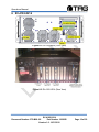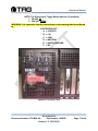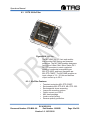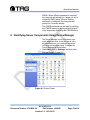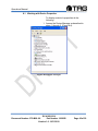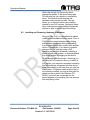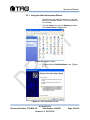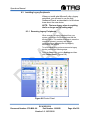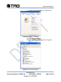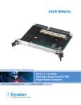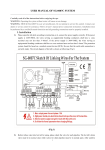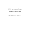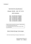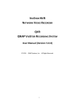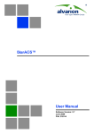
1
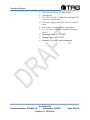
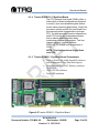
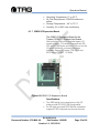
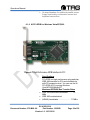
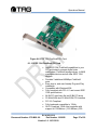
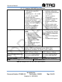
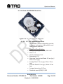
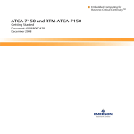
4U Single Quad Core Xeon PICMG Server SV-4102-X214 Operations Manual 279-MNL-006 TAG 22355 TAG Way Dulles, VA 20166 Operations Manual 1 Copyright © 2008 Technology Advancement Group®, Inc. (TAG®) All rights reserved. This publication and its contents are proprietary to TAG. No part of this publication may be reproduced in any form or by any means without the written permission of TAG, 22355 TAG Way, Dulles, Virginia 20166-9310. TAG has made every effort to ensure the correctness and completeness of the material in this document. TAG shall not be liable for errors contained herein. The information in this document is subject to change without notice. TAG makes no warranty of any kind with regard to this material, including, but not limited to, the implied warranties of merchantability and fitness for a particular purpose. 1.1 Trademarks All trademarks, marks, names, or product names referenced in this publication are the property of respective owners, and TAG neither endorses nor otherwise sponsors any such products or services referred to herein. SV-4102-X214 Document Number: 279-MNL-06 Part Number 1008930 Version 1.0. 10/11/2010 Page 2 of 50 Operations Manual 2 About TAG 2.1 Summary of Qualifications TAG has served as a leading provider of IT solutions to DoD customers over the past 20+ years and has a long-standing and respected history of providing Systems Engineering, Electronic Equipment and Program Management support to US Military warfighters. Headquartered in Dulles, Virginia, TAG’s state-of-the-art 35,000 sq. ft. engineering and manufacturing facility provides all the infrastructure, equipment, and manpower necessary to engineer, design, test, manufacture, and certify products to the rugged requirements of the tactical combat theater. Our facilities in Dulles, VA, San Diego, CA, and St. Louis, MO, allow for rapid deployment of products and support across the globe. TAG quickly, efficiently, and cost-effectively tailors rugged solutions for large DoD programs with specific MIL-STD requirements. TAG’s comprehensive Quality Assurance (QA) policy – enforced through application of our UL-registered ISO 9001:2000 certified processes – enables TAG to rapidly deploy systems and solutions that reliably withstand the stresses of the tactical environment. Today, there are over 20,000 TAG systems deployed across various weapons platforms throughout the US Military. TAG effectively balances all corporate assets – our people, expertise, infrastructure, and experience – to consistently and successfully execute and deliver to the DoD. TAG’s success lies in focusing on the corporate Mission Statement and leveraging the tenets of our business model to ensure the customer’s expectations are exceeded throughout lengthy program lifecycles. TAG’s Mission is to resolve our customers’ IT challenges with World-Class: Engineering; Manufacturing and Integration; and Lifecycle Management TAG has a proven track record in implementing these tenets to serve as a trusted advisor to our Government customers. TAG uses this foundation to ensure risk is mitigated, expectations are exceeded, and the customer can consistently rely on the company, our equipment, and our services. SV-4102-X214 Document Number: 279-MNL-06 Part Number 1008930 Version 1.0. 10/11/2010 Page 3 of 50 Operations Manual 2.2 Core Competences 2.2.1 Engineering TAG’s engineering methodology is built upon Multi-Disciplinary Optimization (MDO) and rigorous design reviews. Although PMs drive the schedule at TAG, Engineering leverages Computer-Aided Design (CAD) tools, Computational Fluid Dynamics (CFD) modeling, rapid prototyping processes, and diverse test equipment and facilities to ensure requirements are being met at every step of the design. TAG Engineering follows a proven design-review process, ensuring all entrance and exit criteria are met at each stage. Rigorous documentation is compiled to demonstrate requirement compliance, risks are mitigated, and decisions are prudent – throughout the design process. TAG prides itself on its engineering laboratories and facilities. Over the past three years, TAG has invested in several pieces of equipment that allow TAG to test and certify products directly onsite to the harshest environmental requirements of military standards – including the MIL-STD810F and DO 160D. TAG’s onsite test equipment currently includes a Highly Accelerated Lifecycle Testing (HALT) Chamber, an Electromagnetic Interference (EMI) test chamber, and a high-/low-temperature thermal test chamber. TAG’s facility also provides: A floor plan designed to support a cellular manufacturing model with modular assembly lines A dedicated 24-hour system burn-in room A modern production status tracking and Enterprise Resource Planning (ERP) system with external web collaboration capabilities Dedicated Quality Assurance workstations for system compliance and validation inspection 2.2.2 Manufacturing and Integration TAG implements Cellular Manufacturing processes through our compartmentalized, state-of-the-art production facility to minimize waste byproducts and maximize production efficiency. TAG’s manufacturing facility is physically partitioned to model the major philosophies of Lean Manufacturing. Consistent with the model, each of TAG’s SV-4102-X214 Document Number: 279-MNL-06 Part Number 1008930 Version 1.0. 10/11/2010 Page 4 of 50 Operations Manual production cells are capable of operating in isolation; however personnel and tools are shared across all cells to streamline manufacturing operations, costs, and the production/integration scheduling. TAG’s floor technicians are cross-trained in multiple disciplines so they can be redistributed to any cell that encounters production bottlenecks, which ensures optimal efficiency. 2.2.3 Lifecycle Management TAG’s world-class Program Management discipline models the renowned methodologies of the Project Management Institute (PMI) to ensure successful completion of the task at hand. Our Program Managers (PMs) serve as the voice of the customer – driving requirements to which the rest of TAG’s organization answers. As an explicit tenet of TAG’s corporate mission statement, the PMs not only track cost, schedule, and technical compliance throughout a project’s period of performance, but also ensure the customer is supported well beyond it. SV-4102-X214 Document Number: 279-MNL-06 Part Number 1008930 Version 1.0. 10/11/2010 Page 5 of 50 Operations Manual Document Revision History Date 10/11/2010 Version Number 1.0 Updated By Alan Huckerby Description of Changes Author SV-4102-X214 Document Number: 279-MNL-06 Part Number 1008930 Version 1.0. 10/11/2010 Page 6 of 50 Operations Manual 3 About This Manual 3.1 Scope and Audience This Manual provides an introductory overview of the SV-4102-X214. Designed to endure the rigors of harsh environments, this device can withstand shock and vibration, high and low temperatures. All of our devices are based on the latest Intel and AMD technology. Also, this device doesn't use Intel Core Due or Pentium M technology (only THS servers). . Configuration options include extended memory and enhanced video optimization. All of our servers are backed by our world-class lifecycle management and post sales support. 3.1.1 Organization: This manual is divided into the following chapters: Chapter 1 Provides Cautions and Warnings. Chapter 2 Provides operational information. Chapter 3 Contains all relevant Procedures. SV-4102-X214 Document Number: 279-MNL-06 Part Number 1008930 Version 1.0. 10/11/2010 Page 7 of 50 Operations Manual Table of Contents Contents 1 Copyright © 2008 Technology Advancement Group®, Inc. (TAG®) ............................ 2 1.1 Trademarks ............................................................................................................ 2 2 About TAG ................................................................................................................... 3 2.1 Summary of Qualifications ...................................................................................... 3 2.2 Core Competences................................................................................................. 4 2.2.1 Engineering ....................................................................................................... 4 2.2.2 Manufacturing and Integration........................................................................... 4 2.2.3 Lifecycle Management ...................................................................................... 5 3 About This Manual ....................................................................................................... 7 3.1 Scope and Audience .............................................................................................. 7 3.1.1 Organization: ..................................................................................................... 7 4 Safety Instructions ....................................................................................................... 12 4.1 Types of Warnings used in this Manual .................................................................. 12 4.1.1 Safety Symbols and Labels ............................................................................... 12 4.1.2 Conventions ...................................................................................................... 12 5 SV-4102-X214 Overview ............................................................................................. 15 5.1 Product Information ................................................................................................ 15 6 SV-4102-X214 ............................................................................................................. 16 6.1.1 SV-4102-X214‖ Specifications .......................................................................... 18 6.1.2 SV-4102-X214 Components ............................................................................. 19 6.1.3 Server-Class PCI Express Backplane ............................................................... 19 6.1.4 Trenton PICMG 1.3 Sys/Host Board ................................................................ 21 6.1.5 Trenton PICMG 1.3 Sys/Host Board Components ............................................ 21 6.1.6 PCI Express System Host Board Components ................................................. 22 6.1.7 IOB30 I/O Expansion Board .............................................................................. 23 6.1.8 NI PCI-GPIB for Windows Vista/XP/2000.......................................................... 24 6.1.9 IEEE 1394 FireWire® PCI Card ........................................................................ 26 6.1.10 IEEE 1394 FireWire® PCI Card ...................................................................... 27 6.1.11 Adaptec SAS RAID ......................................................................................... 29 6.1.12 3.5inch 15K-RPM SAS Hard Drive .................................................................. 31 6.2 Power Management ............................................................................................... 33 6.2.1 Power Supply .................................................................................................... 33 6.2.2 Power Supply Components ............................................................................... 34 6.3 COTS 28 Vin Filter ................................................................................................. 36 6.3.1 Vin Filter Features ............................................................................................. 36 7 Procedures .................................................................................................................. 38 7.1 SV-4102-X214 Startup ........................................................................................... 38 7.2 SV-4102-X214 Shutdown ....................................................................................... 38 SV-4102-X214 Document Number: 279-MNL-06 Part Number 1008930 Version 1.0. 10/11/2010 Page 8 of 50 Operations Manual 8 Identifying Server Components Using Device Manager ............................................... 39 8.1 Working with Device Properties .............................................................................. 42 8.2 Installing and Removing Hardware in Windows...................................................... 44 8.2.1 Using the Add New Hardware Wizard ............................................................... 45 8.3 Installing Legacy Peripherals .................................................................................. 46 8.3.1 Removing Legacy Peripherals .......................................................................... 46 8.4 TAG Approved BIOS .............................................................................................. 49 8.4.1 BIOS Configuration for Nightvision .................................................................... 49 SV-4102-X214 Document Number: 279-MNL-06 Part Number 1008930 Version 1.0. 10/11/2010 Page 9 of 50 Operations Manual List of Figures Figure 5-1 SV-4102-X214 ............................................................................................. 15 Figure 6-1 SV-4102-X214 (Front View) ......................................................................... 16 Figure 6-2 SV-4102-X214 (Rear View).......................................................................... 16 Figure 6-3 Warning Label .............................................................................................. 17 Figure 6-4 PCI Express Backplane ............................................................................... 19 Figure 6-5 Trenton PICMG 1.3 Sys/Host Board ............................................................ 21 Figure 6-6 IOB30 I/O Expansion Board ................................................................... 23 Figure 6-7 High-Performance GPIB Interface for PCI ............................................................... 24 Figure 6-8 IEEE 1394 FireWire® PCI Card ................................................................... 27 Figure 6-9 Adaptec 5805 ............................................................................................... 29 Figure 8-1 Control Panel ............................................................................................... 39 Figure 8-2 System Properties ........................................................................................ 40 Figure 8-3 Device Manger ............................................................................................. 40 Figure 8-4 Device Manager ........................................................................................... 42 Figure 8-5 Properties Dialog Box .................................................................................. 43 Figure 8-6 Control Panel ............................................................................................... 45 Figure 8-7 Add Hardware Wizard .................................................................................. 45 Figure 8-8 Control Panel ............................................................................................... 46 Figure 8-9 System Properties ........................................................................................ 47 Figure 8-10 Device Manager ......................................................................................... 47 List of Tables Table 6-1 Specifications. ............................................................................................... 29 Table 6-2 Adaptec SATA & SAS RAID Specifications................................................... 30 SV-4102-X214 Document Number: 279-MNL-06 Part Number 1008930 Version 1.0. 10/11/2010 Page 10 of 50 Operations Manual Chapter 1 Cautions and Warnings. Electronically distributed. Subject to user discretion when printed. SV-4102-X214 Document Number: 279-MNL-06 Part Number 1008930 Version 1.0. 10/11/2010 Page 11 of 50 Operations Manual 4 Safety Instructions 4.1 Types of Warnings used in this Manual Read this manual thoroughly, paying special attention to the cautions and warnings. 4.1.1 Safety Symbols and Labels DANGER WARNING CAUTION These warnings and cautions indicate situations or practice that might result in property damage. 4.1.2 Conventions 4.1.2.1 Important Messages Important messages appear where mishandling of components is possible or when work orders can be misunderstood. These messages also provide vital information associated with other aspects of system operation. The word ―important‖ is written as ―IMPORTANT,‖ both capitalized and bold and is followed by text in italics. The italicized text is the important message. 4.1.2.2 Warnings Warnings appear where overlooked details may cause damage to the equipment or result in personal injury. Warnings should be taken seriously. Warnings are easy to recognize. The word ―warning‖ is written as ―WARNING,‖ both SV-4102-X214 Document Number: 279-MNL-06 Part Number 1008930 Version 1.0. 10/11/2010 Page 12 of 50 Operations Manual capitalized and bold and is followed by text in italics. The italicized text is the warning message. 4.1.2.3 Cautions Cautionary messages should also be heeded to help you reduce the chance of losing data or damaging the system. Cautions are easy to recognize. The word ―caution‖ is written as ―CAUTION,‖ both capitalized and bold and is followed by text in italics. The italicized text is the cautionary message. 4.1.2.4 Notes Notes inform the reader of essential but noncritical information. These messages should be read carefully as any directions or instructions contained therein can help you avoid making mistakes. Notes are easy to recognize. The word ―note‖ is written as ―NOTE,‖ SV-4102-X214 Document Number: 279-MNL-06 Part Number 1008930 Version 1.0. 10/11/2010 Page 13 of 50 Operations Manual Chapter 2 SV-4102-X214 . Electronically distributed. Subject to user discretion when printed. SV-4102-X214 Document Number: 279-MNL-06 Part Number 1008930 Version 1.0. 10/11/2010 Page 14 of 50 Operations Manual 5 SV-4102-X214 Overview Figure 5-1 SV-4102-X214 5.1 Product Information The SV-4102-X214 sets the standard for Servers with state-of-the-art technology. The newest Server can stand up to the harshest environments, and is designed specifically to be fully customized to support unique, missioncritical applications. Your system may contain components not described in this User Manual. For detailed information on these components, refer to the manufactures website or contact TAG Technical Support at [email protected]. SV-4102-X214 Document Number: 279-MNL-06 Part Number 1008930 Version 1.0. 10/11/2010 Page 15 of 50 Operations Manual 6 SV-4102-X214 Figure 6-1 SV-4102-X214 (Front View) Figure 6-2 SV-4102-X214 (Rear View) SV-4102-X214 Document Number: 279-MNL-06 Part Number 1008930 Version 1.0. 10/11/2010 Page 16 of 50 Operations Manual NOTE: The Power Input Toggle Switch has two (2) positions: 1. 28 VDC UP 2. 220 VAC DOWN WARNING: It is imperative that the instructions on the warning label are adhered to. CUSTOM PIN OUT: A. = (+28VDC) B. = (-V) C. = LINE D. = NEUTRAL E. = EARTH GROUND F. = NC Figure 6-3 Warning Label SV-4102-X214 Document Number: 279-MNL-06 Part Number 1008930 Version 1.0. 10/11/2010 Page 17 of 50 Operations Manual 6.1.1 SV-4102-X214” Specifications Chassis & Power Supply Dimensions: 7‖H x 17.125‖W x 20.750‖D. Weight: 30 lbs. Input Voltage: The input power is 28VDC OR 220 VAC. System Specifications. Intel Quad Core Low-voltage CPU (L5408, 2.13GHz). Cache: 12MB L2 Cache. Memory: 4GB (2 x 2GB Modules)/Expandable to 8GB. Type: FB-DIMM RAM. System Management: Intelligent fan controller. With Custom Thermal solution to provide operation in extreme temperature environment Environmentally aware Acoustically optimized Additional Components: 2X 3.5inch 15K-RPM SAS Hard Drives. Trenton PICMG 1.3 Sys/Host Board. IOB30 I/O Expansion Board. NI PCI-GPIB for Windows Vista/XP/2000. Server-Class PCI Express Backplane. IEEE 1394 FireWire® PCI Card. Adaptec 5805 Card. Low-profile DVD±RW/CD-RW drive SV-4102-X214 Document Number: 279-MNL-06 Part Number 1008930 Version 1.0. 10/11/2010 Page 18 of 50 Operations Manual Maintenance and Repair The SV-4102-X214 is considered a line replaceable unit (LRU) and will be maintained and spared at the LRU level. 6.1.2 SV-4102-X214 Components This section provides an overview of the most common components installed in the SV-4102X214. Information is also provided on how to identify specific components within your SV4102-X214. For detailed information on the specific components installed, refer the manufactures websites. 6.1.3 Server-Class PCI Express Backplane Figure 6-4 PCI Express Backplane Specifications 1 4 -slot form factor supports PCI Express, PCI-X and PCI option cards O ne SHB Express (PICMG 1 .3 ) System Host Board Slot (Server Class) SV-4102-X214 Document Number: 279-MNL-06 Part Number 1008930 Version 1.0. 10/11/2010 Page 19 of 50 Operations Manual O ne x1 6 and one x8 PCI Express Slot (mechanical) Two PCI-X 6 4 -bit/ 1 3 3 MHz Slots and Eight PCIX 6 4 -bit/ 1 0 0 MHz Slots PCI-X slots support universal, 6 4 -bit/ 3 2 -bit PCI cards Four USB 2 .0 backplane I/ O connections* * Two 1 0 / 1 0 0 / 1 0 0 0 Base-T backplane Ethernet ports* * Operating Temp: 0°C to 60°C Storage Temp: -20° to 70°C Humidity: 5% to 90% non-condensing. SV-4102-X214 Document Number: 279-MNL-06 Part Number 1008930 Version 1.0. 10/11/2010 Page 20 of 50 Operations Manual 6.1.4 Trenton PICMG 1.3 Sys/Host Board The PCI Systems Host board (SHBs) offers a wide variety of board configurations designed to excel in your most demanding and diverse server-class computing applications. Dual-Core processor options provide two and Quad-Core processors provide four execution cores per CPU. For dual-processor board configurations, each CPU has its own independent system bus to reduce data bottlenecks while maximizing processing throughput. The fourchannel memory interface features DDR2-667 FB-DIMMS with a maximum of 16GB. NOTE: This Unit provides a Single Quad core CPU. 6.1.5 Trenton PICMG 1.3 Sys/Host Board Components Dual or Quad-Core Intel® Xeon® Processors with Independent Front Side Bus Support, Quad Channel DDR2-667 Memory Interface Up to 16GB Ultro ATA/100 Interface. Duel USB Interfaces. Figure 6-5 Trenton PICMG 1.3 Sys/Host Board SV-4102-X214 Document Number: 279-MNL-06 Part Number 1008930 Version 1.0. 10/11/2010 Page 21 of 50 Operations Manual Figure 6-9 MCG-Series PICMG 1.3 PCI Express System Host Board 6.1.6 PCI Express System Host Board Components Dual- or Quad-Core Intel® Xeon® Processors and the Intel® 5000P chipset. A single-board design with two processors that provide up to eight processor execution cores per board (1 + 2 = 8 An independent 1066/1333MHz system bus for each processor. Support for 32-bit and 64-bit operating systems. A four-channel system memory interface with standard memory (16GB) and extended memory (32GB) support. Six SATA/300 ports that support RAID 0, 1, 5 and 10 drive arrays. Three Gigabit Ethernet interfaces and eight USB 2.0 ports. Supports PCI Express™, PCI-X and PCI option cards. Power and Backplane I/O Connector. Operating Temperature: 0° to 40° C. (3.16GHz X5460 CPUs) Operating Temperature: 0° to 55° C. (L5408 and LV5138 CPUs) SV-4102-X214 Document Number: 279-MNL-06 Part Number 1008930 Version 1.0. 10/11/2010 Page 22 of 50 Operations Manual Operating Temperature: 0° to 45° C. Air Flow Requirement: 300LFM continuous airflow Storage Temperature: - 40° to 70° C. Humidity: 5% to 90% non-condensing 6.1.7 IOB30 I/O Expansion Board The IOB30 I/O Expansion Board for the Trenton PICMG 1.3 System Host Boards Optional plug-in module provides legacy I/O system support. This board Features two RS232 serial COM ports and one PS/2 port on the I/O plate Additional on-board interfaces available Supports Trenton TQ9, MCX and MCG-series PICMG 1.3 SHBs Figure 6-6 IOB30 I/O Expansion Board Specifications Two DB9 serial port connectors on the I/O plate provide RS-232 COM functionality An I/O plate mounted PS/2 MiniDin connector supports PS/2 keyboard and mouse devices SV-4102-X214 Document Number: 279-MNL-06 Part Number 1008930 Version 1.0. 10/11/2010 Page 23 of 50 Operations Manual On board headers for additional parallel printer, floppy functionality or alternative mouse and keyboard connections 6.1.8 NI PCI-GPIB for Windows Vista/XP/2000 Figure 6-7 High-Performance GPIB Interface for PCI Specifications PCI-GPIB is a high-performance plug-and-play IEEE 488 interface for PCs and workstations with PCI expansion slots. You can use the NI PCI-GPIB in PCs running Windows Vista/XP/2000/Me/9x/NT. Maximum IEEE 488 Bus Transfer Rates IEEE 488 interlocked handshake......... 1.5 MB/s IEEE 488 noninterlocked (HS488) handshake......................... 7.7 MB/s SV-4102-X214 Document Number: 279-MNL-06 Part Number 1008930 Version 1.0. 10/11/2010 Page 24 of 50 Operations Manual (actual rates depend on system configuration and instrument capabilities) GPIB Analyzer Performance Sampling rate...................................... 20 MHz Timestamp resolution ......................... 50 ns Ethernet Performance 10BASE-T 10 Mb/s, full-duplex 100BASE-TX 100 Mb/s, full-duplex 1000BASE-T 1000 Mb/s, full-duplex Power Requirements PCI-GPIB, PXI-GPIB, PCI-GPIB/LP (183617x01-based board) +5 VDC 1.5 W typical, 2.25 W maximum PCI-GPIB, PXI-GPIB (188513x-01-based board) +3.3 VDC 0.4 W typical, 0.6 W maximum PCI-GPIB+ +3.3 VDC 0.6 W typical, 1.9 W maximum PCI-8232 +5 VDC. 4.4 W typical, 5.8 W maximumPXI-8232 +3.3 VDC 3.0 W typical, 4.0 W maximum PCI signaling level Universal Physical Dimensions PCI (183617x-01-based board)............ 13.3 by 10.7 cm (5.3 by 4.2 in.) PCI (188513x-01-based board)............ 12.0 by 6.44 cm (4.72 by 2.54 in.) PCI (low-profile) .................................. 12.0 by 6.44 cm (4.72 by 2.54 in.) PXI ....................................................... 16 by 10 cm (6.3 by 3.9 in.) I/O Connectors GPIB.. IEEE 488 standard 24-pin Ethernet........................................ RJ45 Operating Environment SV-4102-X214 Document Number: 279-MNL-06 Part Number 1008930 Version 1.0. 10/11/2010 Page 25 of 50 Operations Manual Ambient temperature............. 0 to 55 °C Relative humidity . 10 to 90%, noncondensing (tested in accordance with IEC-60068-2-1, IEC-60068-2-2, and IEC-60068-2-56) Storage Environment Ambient temperature.......... -20 to 70 °C Relative humidity .. 5 to 95%, noncondensing (tested in accordance with IEC-60068-2-1, IEC-60068-2-2, and IEC-60068-2-56) Shock and Vibration PXI-GPIB, PXI-8232 Functional shock .......... 30 g peak, half-sine, 11 ms pulse (tested in accordance with IEC-60068-2-27; test profile developed in accordance with MIL-PRF-28800F) Random vibration Operating....... 5 to 500 Hz, 0.3 grms Nonoperating............... 5 to 500 Hz, 2.4 grms (tested in accordance with IEC-60068-264;nonoperating test profile exceeds the requirements of MIL-PRF-28800F, Class 3) 6.1.9 IEEE 1394 FireWire® PCI Card Used to add FireWire® capabilities to PCs without FireWire® ports, or for current users desiring extra ports on an existing FireWire® system. Simply slides into an empty PCI slot. SV-4102-X214 Document Number: 279-MNL-06 Part Number 1008930 Version 1.0. 10/11/2010 Page 26 of 50 Operations Manual Figure 6-8 IEEE 1394 FireWire® PCI Card 6.1.10 IEEE 1394 FireWire® PCI Card Add IEEE 1394 FireWire® capabilities to your PC, and instantly connect digital video camcorders, FireWire® storage drives, i.LINK® compatible devices and all other IEEE 1394 devices. Provides 3 additional 400Mbps FireWire® ports. Easy drop in, and user-friendly Plug-and-Play installation. Compatible with Windows® 98. Fully compliant with PCI v2.1 and current IEEE 1394 specifications. 64 Bit PCI card (also fits into32 Bit PCI slots) 33 MHz/64 Bit and 33 MHz/32 Bit PCI Interface PCI 2.2 Compliant Fully backward compatible to 1394a OHCI Compliant 1394b Host controller with support for 100 Mb/sec. (12.5 MB/sec), 200 SV-4102-X214 Document Number: 279-MNL-06 Part Number 1008930 Version 1.0. 10/11/2010 Page 27 of 50 Operations Manual Mb/sec. (25 MB/sec.), 400 Mb/sec. (50 MB/sec.) and 800 Mb/sec. (100 MB/sec.) data transfer speeds. 1394b Cable power: 12V, 9W max from PCI bus and optional 12V internal connector for power from PC power supply Connect up to 63 devices, up to 16 devices daisy chained together in a single chain. SV-4102-X214 Document Number: 279-MNL-06 Part Number 1008930 Version 1.0. 10/11/2010 Page 28 of 50 Operations Manual 6.1.11 Adaptec SAS RAID The Adaptec RAID 5805 is equipped with industry-leading 1.2GHz DualCore RAID on Chip (ROC), the latest x8 PCI-Express connectivity, and 512MB of DDR2 cache to deliver over 250,000 IO per second and 1.2GB/s. Eight internal ports in this Unified Serial controller allow you to connect up to 256 SATA/SAS disk drives through SAS expanders. The Adaptec RAID 5805 features Adaptec RAID Code (ARC) with RAID levels 0, 1, 1E, 5, 5EE, 6, 10, 50, 60, JBOD, as well as Copyback Hot Spare. Figure 6-9 Adaptec 5805 Adaptec RAID Form Factor Ports Connectors Bus Interface Processor Cache 5805 MD2 - Low Profile 8 internal 2 SFF-8087 (int.) 8-Lane PCIe 1.2 GHz Dual Core 512MB Table 6-1 Specifications. SV-4102-X214 Document Number: 279-MNL-06 Part Number 1008930 Version 1.0. 10/11/2010 Page 29 of 50 Operations Manual 6.1.11.1 Adaptec SAS RAID Specifications RAID Features Management Utilities Operating System Physical Dimensions Operating Temperature(incl. battery) Operating Voltage MTBF Supports up to 256 SATA or Hot spares - global, SAS devices using SAS dedicated, and pooled expanders Automatic/manual rebuild RAID levels 0, 1, 1E, 5, 5EE, of hot spares 6, 10, 50, 60 and JBOD SAF-TE enclosure Quick initialization management Online Capacity Expansion Configurable stripe size Copyback Hot Spare S.M.A.R.T. support Dynamic caching algorithm Multiple arrays per disk drive Native Command Queuing (NCQ) Dynamic sector repair Background initialization Staggered drive spin-up Hot-plug drive support Bootable array support RAID Level Migration Optimized Disk Utilization Adaptec Storage Manager™ ARCCONF (ASM) Command Line Interface Adaptec BIOS Configuration Java-based GUI Utility (ACU) Management Utility Remote configuration, BIOS level configuration monitoring and notification utility ASM OS Support: Flashable BIOS support Windows, Linux, SCO, Solaris, Microsoft VDS Support SNMP, SMTP Remote firmware updates Windows XP, Server 2003/2008, Vista, Red Hat Enterprise Linux (RHEL), SUSE Linux Enterprise Server (SLES), SCO OpenServer, UnixWare, Sun Solaris 10 x86, FreeBSD 5085/5405/5445/5805 — 2.5‖H 51245/51645/52445 — 4.6‖H x x 6.6‖L (167mm x 64mm) 6.43‖L (164mm x 116mm) 0°C to 35°C (without airflow) 0°C to 30°C (without airflow) 0°C to 55°C (with 200 LFM 0°C to 55°C (with 200 LFM airflow) airflow) 0.45A @ 3.3V; 1A @ 12V 0.47A @ 3.3V; 1.8A @ 12V 873,402 hours at 40°C Table 6-2 Adaptec SATA & SAS RAID Specifications. SV-4102-X214 Document Number: 279-MNL-06 Part Number 1008930 Version 1.0. 10/11/2010 Page 30 of 50 Operations Manual 6.1.12 3.5inch 15K-RPM SAS Hard Drive Figure 6-16 3.5‖, SAS, Industrial Hard Drive 6.1.12.1 3.5”, SAS, Industrial Hard Drive The 300GB, 4-platter configuration provides low power consumption, high reliability, and faster internal data rates. Functional Specifications Storage capacity (formatted)1 300.0 GB Disks 1 2 4 Heads (read/write) 2 4 8 Bytes/sector 512 Seek time Track to track Read: 0.2 ms (typ.) / Write: 0.4 ms (typ.) Average Read: 3.4 ms (typ) / Write: 3.9 ms (typ) Full track Read: 8.0 ms (typ) / Write: 9.0 ms (typ) Average latency time 2.00 ms Rotational speed (RPM) 15,000 SV-4102-X214 Document Number: 279-MNL-06 Part Number 1008930 Version 1.0. 10/11/2010 Page 31 of 50 Operations Manual Areal density 112.8 Gbits/sq. in. Data transfer To/from media 179MB/sec rate To/from host SAS: 3Gb/sec, SCSI: 320MB/sec, FCAL: 4Gb/sec Recording code 60/62 MEEPRML Interface Dual Port SAS (RC Series), SCA-2 80Pin (NC Series), 68Pin Wide (NP Series), Dual Port FCAL (FC series) Head positioning method Rotary VCM Start time 30 s (typ) Stop time 30 s (typ) Buffer size SCSI 8 MB SAS, FC 16 MB Physical Specifications Power Voltage 5 V ± 5%, 12 V ± 5% requirements Spin-up 12 V ± 5% @ 2.5 A (peak) A (peak < 100 us) 5 V ± 5% @ 0.8 A Idle (typ.) SAS 12.8 W SCSI 12.4 W FC 13.4 W Dimensions (HxWxD) 25.4 mm x 101.6 mm x 146.0 mm Weight 800 g Ambient Operating 5°C to 55°C (HDD surface 60°C max) temperature Non-operating -40°C to 70°C Gradient 20°C/Hour (max) Relative Operating 5% to 95% (noncondensing) humidity Non-operating 5% to 95% (noncondensing) Max. wet bulb 29°C (operating) Vibration Operating 0.6 mm (5 to 20 Hz) / 1.0 G (20 to 300 Hz) Non-operating 3.1 mm (5 to 20 Hz) / 5.0 G (20 to 300 Hz) Shock Operating 65 G max. (2 ms) SV-4102-X214 Document Number: 279-MNL-06 Part Number 1008930 Version 1.0. 10/11/2010 Page 32 of 50 Operations Manual Non-operating 250 G max. (2 ms) Altitude Operating 3,048 m (max.) (operation) Non-operating 12,192 m (max.) Acoustic Noise (idle sound power) (typ.) </= 3.6 bels (idle) Reliability Specifications 6.2 Mean time between failures (MTBF) 1,400,000 hours Error rates Unrecoverable errors 1 per 1015 bits read Seek errors 10 per 108 seeks Power Management Modern motherboards provide Advanced Configuration and Power Management Interface (ACPI) settings such as wake-up, power button function and standby/suspend timers. These functions are configured in the CMOS Setup. (Section 8-4 BIOS Setup). 6.2.1 Power Supply Two 300W DC power supply modules are supplied. One 300W DC module will supply power solely to the .backplane ATX connector. The second 300W DC module will supply all other power requirements. Including power supply to auxiliaries such as: Fans, HD, etc. Figure 6-17 Zippy Power Supply SV-4102-X214 Document Number: 279-MNL-06 Part Number 1008930 Version 1.0. 10/11/2010 Page 33 of 50 Operations Manual 6.2.2 Power Supply Components Output Wattage 300W. Dimension 225.00x100.00x40.50mm. 8,85x3.94x1.59‖ inch. DC Input Spec Voltage: DC20V~28V Input Current: 20.0A (RMS) for 24VDC. Inrush Current: 20.0A Max. Temperature range: operating 10℃~40℃. Humidity:operating:20%-95%, nonoperating:10%-95%. Remarks: 85% is normal condition and 95% is with special coating process. Hold up time1.6ms minimum at full load & nominal input voltage. Dielectric withstand: input/output 1500 vac for 1 second. Input to frame ground 1500 vac for 1 second. Efficiency: 65% typical at full load*power good signal: on delay 100ms to 500ms. Overload Protection:130±20%. Over Voltage Protection: +5v→5.5v~7.0v , +3.3v→4.0v~4.5v. Short Circuit Protection: +5v、+12v、+3.3v. Emi Noise Filter :fcc class a, cispr22 class a. Safety : ul 60950, csa 22.2 iec60950, tuv en60950. Remote on/off Control. The unit shall accept a logic open collector level which will disable/enable all the output voltage (exclude +5v stand by). SV-4102-X214 Document Number: 279-MNL-06 Part Number 1008930 Version 1.0. 10/11/2010 Page 34 of 50 Operations Manual As logic level is low, outputs voltage were enabled. As logic level is high, outputs voltage were disabled. Cooling :two 40mm dc fans. SV-4102-X214 Document Number: 279-MNL-06 Part Number 1008930 Version 1.0. 10/11/2010 Page 35 of 50 Operations Manual 6.3 COTS 28 Vin Filter Figure 6018 Vin Filter The M-FIAM5 is a DC front-end module that provides EMI filtering and transient protection. The M-FIAM5 enables designers using Vicor’s Maxi, Mini, Micro Series 24 V DC-DC converters to meet conducted emission/ conducted susceptibility per MIL-STD-461E; and input transients per MIL-STD-704E/F. The M-FIAM5 accepts an input voltage of 14 – 36 Vdc and delivers output current up to 20 A. 6.3.1 Vin Filter Features • Transient protection-MIL-STD-704E/F. • Environments-MIL-STD-810, MIL-STD- 202. • Environmental stress screening. • Low profile mounting options. • Output current up to 20 A. • Mini sized package. • Inrush current limiting. • Reverse polarity protection. SV-4102-X214 Document Number: 279-MNL-06 Part Number 1008930 Version 1.0. 10/11/2010 Page 36 of 50 Operations Manual Chapter 3 Procedures. Electronically distributed. Subject to user discretion when printed. SV-4102-X214 Document Number: 279-MNL-06 Part Number 1008930 Version 1.0. 10/11/2010 Page 37 of 50 Operations Manual 7 Procedures The procedures within this Chapter contain relevant information to ensure the SV-4102X214 maintains its maximum performance potential. 7.1 SV-4102-X214 Startup 1. Check to make sure that all the cables are seated and connected correctly to the back of the unit such as keyboard, mouse, monitor video cable and both power cables. 2. Then Press the power switch ON to start the computer (power switch is located in the front of the unit) 3. Once the unit starts, System will go thru Power On self Test (POST) (no action is required at this time) 4. At windows dialog box press Ctrl+Alt+Delete at once to login 5. Type in the correct user name and password and then press enter to login 6. Once the operator is logged on to the unit they could use the computer as they wish. NOTE: Assuming the SV-4102-X214is not connected to any network. 7.2 SV-4102-X214 Shutdown 1. The operator needs to save all data, and then close all applications. 2. Once all data is saved and applications are closed, click on Start menu, select shutdown and then click OK to shutdown the computer. NOTE: Holding down the front panel “on” switch for two (2) seconds shuts down the machine it does not save files. This is an immediate power off switch. 7.2.1.1 Passwords In most cases a user (startup) password and a supervisor (setup) password can be set in the SV-4102-X214 Document Number: 279-MNL-06 Part Number 1008930 Version 1.0. 10/11/2010 Page 38 of 50 Operations Manual CMOS. When a Setup password is required, the computer will prompt for it when you try to access the BIOS setup. When a Startup password is configured, the computer will prompt for it at every startup. The CMOS password can be reset by shorting the "CMOS restore to factory defaults jumper" or by temporarily removing the CMOS battery. 8 Identifying Server Components Using Device Manager The Device Manager is one of Windows' most useful diagnostic tools. It lets you see all of the devices attached to your computer, and which resources they are each using. To access the Device Manager do the following: 1. Click Start, point to Settings, and then click Control Panel. (Figure 8-1). Figure 8-1 Control Panel SV-4102-X214 Document Number: 279-MNL-06 Part Number 1008930 Version 1.0. 10/11/2010 Page 39 of 50 Operations Manual 2. Double-click the System icon. (Figure 8-2). Figure 8-2 System Properties 3. Click the Hardware tab, and then click the Device Manager button. (Figure 8-3). Figure 8-3 Device Manger SV-4102-X214 Document Number: 279-MNL-06 Part Number 1008930 Version 1.0. 10/11/2010 Page 40 of 50 Operations Manual After opening Device Manager, you will see a list of all the devices Windows detected on your system. The Device Manager display is recreated each time the computer is started, or whenever a dynamic change to the computer configuration occurs, such as addition of a new device while the system is running. NOTE: To include hidden devices, on the View menu, click Show hidden devices. A check mark next to Show hidden devices indicates hidden devices are showing. Click it again to clear the check mark. Hidden devices include non-PnP devices and devices that have been physically removed from the computer but have not had their drivers uninstalled. The devices shown represent the computer's current hardware configuration information. Any non-functioning devices are displayed with an exclamation point, indicating that a problem exists with the device; disabled devices are displayed with a small red "x" over the icon. You can use Device Manager to enable or disable devices, troubleshoot devices, update drivers, use driver rollback, and change resources such as interrupt requests (IRQs) assigned to devices. SV-4102-X214 Document Number: 279-MNL-06 Part Number 1008930 Version 1.0. 10/11/2010 Page 41 of 50 Operations Manual 8.1 Working with Device Properties To display a device's properties do the following: 1. Access the Device Manager as described in steps 1 through 3. (Figure 8-4). Figure 8-4 Device Manager SV-4102-X214 Document Number: 279-MNL-06 Part Number 1008930 Version 1.0. 10/11/2010 Page 42 of 50 Operations Manual 2. In the Device manager dialog box (Figure4-4\), double-click the device, or select the device and then click the Properties toolbar button. (Figure 8-5). Figure 8-5 Properties Dialog Box In the device's Properties dialog box, there might be several tabs. You can view the status and configuration information, as well as the device manufacturer, device type, and location in the upper portion of the General tab. The Device status box in the middle of the General tab displays the status of the device, including any errors. If the device has any problems, the Device Status box briefly describes the problem, and usually describes the appropriate course of action to correct the problem. 3. Click Troubleshoot... to use the built-in mechanisms for detecting the nature of the problem. SV-4102-X214 Document Number: 279-MNL-06 Part Number 1008930 Version 1.0. 10/11/2010 Page 43 of 50 Operations Manual Other tabs include the Driver tab, which displays the details of the driver being used. This tab also lets you update or uninstall the driver. The Resources tab displays the hardware resources being used. This tab allows you to see and resolve any conflicts caused by non-PnP devices. Along with these tabs, some devices have additional advanced settings or tabs for device-specific settings. 8.2 Installing and Removing Hardware in Windows Plug and Play (PnP) is a standard that makes installing new hardware devices easier. Prior to PnP, installing new hardware meant finding and installing peripheral drivers and making sure the new device didn't conflict with another device. Theoretically, if you have a computer designed for PnP and are using a PnP operating system (like Windows), installing a printer, sound card, modem, or other peripheral is a simple matter of plugging in the device. It's not always quite this simple. Assuming you are using a PnP computer, when you attach a PnP device, you may see a message indicating that Windows has recognized the new deviceeither immediately or the next time you start up your system. If Windows needs a driver that is not currently installed, you may at that point be asked to insert a disk or the Windows CDROM. If you don't see a message but the device appears to be working, you can assume that everything is fine. SV-4102-X214 Document Number: 279-MNL-06 Part Number 1008930 Version 1.0. 10/11/2010 Page 44 of 50 Operations Manual 8.2.1 Using the Add New Hardware Wizard If the device is not working properly, try using the Add New Hardware Wizard. To run this wizard, do the following: 1. From the Start menu, point to Settings and then click Control Panel. (Figure 8-6). Figure 8-6 Control Panel 2. Double-click the Add Hardware icon. (Figure 8-7). Figure 8-7 Add Hardware Wizard SV-4102-X214 Document Number: 279-MNL-06 Part Number 1008930 Version 1.0. 10/11/2010 Page 45 of 50 Operations Manual 8.3 Installing Legacy Peripherals When you install what Microsoft calls a legacy peripheral, you will need to use the Add Hardware Wizard, as described to let Windows know about the new device. NOTE: The term legacy refers to anything that's no longer on the cutting edge. 8.3.1 Removing Legacy Peripherals When removing a legacy peripheral from your system, you need to let Windows know that the device is gone. This enables Windows to reuse the resources (places in memory and internal communications channels) that it previously allocated to that device. To tell Windows that you have removed a legacy device, perform the following steps: 1. From the Start menu, point to Settings and then click Control Panel. (Figure 8-8). Figure 8-8 Control Panel SV-4102-X214 Document Number: 279-MNL-06 Part Number 1008930 Version 1.0. 10/11/2010 Page 46 of 50 Operations Manual 2. Double-click the System icon. (Figure 8-9). Figure 8-9 System Properties 3. Click the Hardware tab. 4. Click the Device Manager button. (Figure 810). Figure 8-10 Device Manager SV-4102-X214 Document Number: 279-MNL-06 Part Number 1008930 Version 1.0. 10/11/2010 Page 47 of 50 Operations Manual 5. Click the name of the item you have removed from your system. If you don't see the item, look for a category heading that describes the type of device you removed, and then click the plus sign to its left to display a list of items in that category. 6. From the Action menu, click Uninstall. 7. Click OK. SV-4102-X214 Document Number: 279-MNL-06 Part Number 1008930 Version 1.0. 10/11/2010 Page 48 of 50 Operations Manual 8.4 TAG Approved BIOS The BIOS (basic input/output system) is the program stored on the CMOS that the server's microprocessor uses to get the system started after you turn it on. The BIOS also manages data flow between the computer's operating system and attached devices such as the hard disk, video adapter, keyboard, and mouse. CAUTION: The server's hardware and software was loaded and tested with a specific "BIOS" version. If you desire to have the BIOS updated, consult TAG technical support in advance as updates to your approved BIOS may cause your system to become unstable or inoperable. 8.4.1 BIOS Configuration Enter BIOS by pressing Delete when prompted in POST. Once the BIOS Configuration Utility has been entered scroll to the exit tab using the arrow keys. Under the exit menu option select ―Load Optimal Defaults‖ when prompted select OK to load optimal defaults. Scroll back to the Main menu and ensure that all of the settings seen in the screenshots below are set. Upon exit ensure that settings are saved upon exit. NOTE: A BIOS update is under review, as soon as that is completed an addendum to this manual will be dispatched. SV-4102-X214 Document Number: 279-MNL-06 Part Number 1008930 Version 1.0. 10/11/2010 Page 49 of 50 CONTACT 8.4.2 22355 TAG Way Dulles, VA 20166 Tel: 1-800-824-7693 www.tag.com Technical Support USA 1-800-824-7693 Outside USA While every precaution has been taken to ensure the accuracy and completeness of this literature. TAG assumes no responsibility and disclaims and liability for damage resulting from use of this information or for any errors or omissions.