1
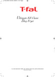
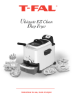
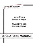
Model OFE-321,322
SECTION 2. MAINTENANCE
2-1. INTRODUCTION
This section provides procedures for the checkout and replacement
of the various parts used within the fryer. Before replacing any
parts, refer to the Troubleshooting Section. It will aid you in
determining the cause of the malfunction.
2-2. MAINTENANCE HINTS
1. You may need to use a multimeter to check the electric
components.
2. When the manual refers to the circuit being closed, the
multimeter should read zero unless otherwise noted.
3. When the manual refers to the circuit being open, the
multimeter will read infinity.
2-3. COMPLETE CONTROL
PANEL REPLACEMENT
Should the control board become inoperative, follow these
instructions for replacing the board.
1. Remove electrical power supplied to the unit.
To avoid electrical shock or property damage, move the
POWER switch to OFF and disconnect main circuit
breaker, or unplug cord at wall receptacle.
2. Remove the four screws securing the control panel and lift
out.
3. Unplug the wire connectors going to the control board.
4. Install new control panel in reverse order.
When plugging connectors onto new control panel, be sure
the connectors are inserted onto all of the pins, and that the
connectors are not forced onto the pins backwards. If not
connected properly, damage to the board could result.
2-1
405
Model OFE-321,322
2-4. POWER SWITCH
1. Remove electrical power supplied to fryer.
To avoid electrical shock or property damage, move the
POWER switch to OFF and disconnect main circuit
breaker, or unplug cord at wall receptacle.
2. Remove control panel.
3. Label and remove the wires from the switch. With test
instrument, check across the terminals of the switch with
the switch in the ON position, then in the OFF position.
With the switch in the ON position, the circuit should be
closed. With the switch in the OFF position, the circuit
should be open. If the switch checks defective, replace by
continuing with this procedure.
4. With control panel removed, and the wires off the switch, push
in on tabs on the switch to remove from panel.
5. Replace with new switch, and reconnect wires to switch.
6. Replace the control panel.
2-5. TRANSFORMER
The transformer reduces voltage down to accommodate those
components with low voltage.
1. Remove electrical power supplied to the unit.
To avoid electrical shock or property damage, move the
POWER switch to OFF and disconnect main circuit
breaker, or unplug cord at wall receptacle.
2. Remove the control panel as discussed in Complete Control Panel
Replacement Section.
3. Squeeze on the wire connector at the I/O board assembly to
disconnect the wires from the transformer.
4. Using a Phillips head screwdriver, remove the two screws
securing the transformer to the shroud.
5. Install the new transformer in reverse order.
405
2-2
Model OFE-321,322
2-6. I/O POWER SUPPLY
BOARD ASSEMBLY
The input/output power supply board assembly distributes
voltage to the various components in the fryer. The board also
receives information from components in the fryer.
1. Remove electrical power supplied to the unit.
To avoid electrical shock or property damage, move the
POWER switch to OFF and disconnect main circuit
breaker, or unplug cord at wall receptacle.
2. Remove the control panel as discussed in Complete Control
Panel Replacement Section.
3. Disconnect the wire assemblies from the board.
4. Using a nut driver or wrench, remove the four keps nuts
securing the board to the shroud.
5. Install the new I/O board assembly in reverse order.
2-7. DRAIN MICROSWITCH
Upon turning the drain handle, the drain microswitch circuit
should open, cutting off the pilot flame. This will prevent the fryer
from heating while shortening is being drained from the frypot.
1. Remove electrical power supplied to the unit.
To avoid electrical shock or property damage, move the
POWER switch to OFF and disconnect main circuit
breaker, or unplug cord at wall receptacle.
2-3
405
Model OFE-321,322
2-7. DRAIN MICROSWITCH
(Continued)
2. The following check should be made to determine if the drain
microswitch is defective.
a. Remove the two screws securing the microswitch to the
drain rod valve bracket.
b. Remove wires from the switch.
c. Check for continuity across the two outside terminals of the
drain switch. If the circuit is open, the drain switch is
defective. The circuit should only be opened by pressing on
the actuator of the drain switch.
3. Replace switch in reverse order.
2-8. FILTER SWITCH
1. Remove electrical power supplied to the unit.
To avoid electrical shock or property damage, move the
POWER switch to OFF and disconnect main circuit
breaker, or unplug cord at wall receptacle.
2. Remove the control panel above the switch.
3. Label and remove the wires from the switch. With test
instrument, check across the terminals of the switch with the
switch in the ON position, and then in the OFF position. With
the switch in the ON position, the circuit should be closed.
With the switch in the OFF position, the circuit should be open.
If the switch checks defective, replace it by continuing with
this procedure.
4. With wires removed from the switch, push in on tabs on the
switch and remove switch from the panel.
5. Push new switch into panel and reconnect wires.
405
2-4
Model OFE-321,322
2-9. HEATING ELEMENTS
Heating elements are available for 208, 480 and 230 volts. Check
data plate to determine correct voltage.
Checkout:
If the shortenings temperature recovery is very slow or at a slower
rate than required, this may indicate defective heating element(s).
An ohmmeter will quickly indicate if the elements are shorted or
open.
1. Remove electrical power supplied to the frypot to be worked on.
To avoid electrical shock or property damage, move the
POWER switch to OFF and disconnect main circuit
breaker, or unplug cord at wall receptacle, to the frypot
to be worked on. Be aware the other controls will have
power.
2. Remove control panel.
3. Perform an ohm check on one element at a time, with wires
disconnected from element. If the resistance is not within
tolerance, replace the element.
Voltage
Wattage
208
7333
240
7333
480
7333
Replacement:
Resistance Ohms (cold)
5.6
6.9
27.5
Refer to figure 2-2.
1. Drain the shortening from the frypot.
2. Remove the high limit bulb holder from the heating element
inside the frypot.
2-5
405
Model OFE-321,322
2-9. HEATING ELEMENTS
(Continued)
3. Remove the heating element wires from the terminals by
removing the nuts and washers. Label each so it can be
replaced on the new element in the same position.
4. Remove the bolts from the five element spreaders. The
element spreaders will now pull off the elements.
5. Remove the brass nuts and washers which secure the ends of
the elements through the frypot wall.
6. Remove the heating elements from the frypot as a group by
lifting the far end and sliding them up and out toward the
rear of the frypot.
Always install new rubber O-rings when installing heater
elements.
7. Install new heating elements with the new O-rings, terminal
end first at approximately a 45° angle, slipping the terminals
through the front wall of the frypot.
8. Replace the brass nuts and washers on the element terminals.
Tighten the brass nuts to 30 foot lbs. of torque.
9. Evenly space the element spreaders on the sides of the
elements and reinstall bolts. Place the fifth spreader in the
front of the elements as to protect the temperature probe.
(Fig.2-1
10. Replace the high limit bulb holder on the top element, and
position the bulb between the top and second element
midway from side to side, and tighten screw that holds the
bulb in place.
11. Reconnect the wires to the appropriate terminal as labeled
when they were removed.
Temperature
Probe
Spreader
Fig. 2-1
405
12. Replace the front control panel.
2-6
Model OFE-321,322
2-9. HEATING ELEMENTS
(Continued)
13. Connect the power cord to the wall receptacle or close wall
circuit breaker.
Heating elements should never be energized without
shortening in the frypot, or damage to the elements could
result.
14. Replace the shortening in the frypot.
Fig. 2-2
2-7
405
Model OFE-321,322
2-10. HEATING
CONTACTORS
Each well of an electric fryer requires two switching contactors.
The first in line is the primary contactor and the second in line is
the heat contactor. When open, the primary contactor does not
allow power to flow to the heat contactor. When closed, the
primary supplies voltage to the heat contactor. When the heat
contactor is open, no voltage is supplied to the heating elements.
When the heat contactor closes, voltage is supplied to the heating
elements.
Checkout (Power Removed)
1. Remove electrical power supplied to the frypot to be worked on.
To avoid electrical shock or property damage, move the
POWER switch to OFF and disconnect main circuit
breaker, or unplug cord at wall receptacle, to the frypot
to be worked on. Be aware the other controls will have
power.
2. Remove the control panel.
30
31
32
3. Perform a check on the contactor as follows:
Test Points
33
From 30 to 34
From 31 to 35
From 32 to 36
From 33 to 37
37
34
35
Results
open circuit
open circuit
open circuit
ohm reading 1700
Wires should be removed and labeled to obtain an accurate check
of contactors.
36
Mercury Contactor
405
2-8
Model OFE-321,322
2-10. HEATING
CONTACTORS
(Continued)
Checkout (Power Supplied)
To avoid electrical shock, make connections before
applying power, take reading, and remove power before
removing meter leads. The following checks are
performed with the wall circuit breaker closed and the
main power switch in the ON position.
1. Re-apply power to unit and turn POWER switch ON.
2. Using illustrations from previous page, check voltage as
follows:
Test Points
From terminal 34 to 35
From terminal 35 to 36
From terminal 34 to 36
Results
The voltage should read
the same at each terminal
Replacement:
If either contactor is defective it must be replaced as follows:
To avoid electrical shock or property damage, move the
POWER switch to OFF and disconnect main circuit
breaker, or unplug cord at wall receptacle, to the frypot
to be worked on. Be aware the other controls will have
power.
1. Remove only the wires directly connected to the contactor being
replaced. Label the wires for replacement.
2. Loosen the screws securing the contactor bracket to the shroud.
3. Remove the contactor from the bracket.
4. Reinstall in reverse order.
2-9
405
Model OFE-321,322
2-11. SPEAKER ASSEMBLY
The speaker assembly emits audible signals to let the operator
know when cooking and hold times are finished.
1. Remove electrical power supplied to unit.
To avoid electrical shock or property damage, move the
POWER switch to OFF and disconnect main circuit
breaker, or unplug cord at wall receptacle.
2. Remove control panel.
3. Follow the speaker wire and disconnect from control board.
4. Remove the screws securing the speaker bracket to the shroud.
5. Remove the speaker from the bracket.
6. Reinstall in reverse order.
2-12. HIGH TEMPERATURE
LIMIT CONTROL
The electric units, model OFE-321/2/3/4, use the same high
temperature control limits as the gas units, OFG-321/2/3/4, but
the mounting of the capillary tube is different on the electric
units compared to the gas units.
Checkout:
Use the same procedure as in the High Limit Temperature Control
(Gas) Section.
Replacement:
To avoid electrical shock or property damage, move the
POWER switch to OFF and disconnect main circuit
breaker, or unplug cord at wall receptacle, to the frypot
to be worked on. Be aware the other controls will have
power.
405
2-10
Model OFE-321,322
2-12. HIGH TEMPERATURE
LIMIT CONTROL
The electric units, models OFE-321/2/3/4, use the same high
temperature control limits as the gas units, but the mounting of the
capillary tube is different on the electric units compared to the gas
units.
Checkout:
Use the same procedure as in the High Limit Temperature Control
(Gas) Section.
Use replacement high limit, part no. 60241, 425 degree.
Replacement:
To avoid electrical shock or property damage, move the
POWER switch to OFF and disconnect main circuit
breaker, or unplug cord at wall receptacle, to the frypot
to be worked on. Be aware the other controls will have
power.
1. Drain the shortening from the frypot.
2. Remove control panel.
3. Loosen small inside screw nut on capillary tube.
4. Remove capillary bulb from bulb holder inside the frypot.
5. Straighten the capillary tube.
6. Remove larger outside nut that threads into pot wall.
7. Remove the two screws that secure the high limit to the high
limit bracket.
8. Remove the defective control from the control panel area.
2-11
409
Model OFE-321,322
2-12. HIGH TEMPERATURE
LIMIT CONTROL
(Continued)
Be sure capillary bulb of high limit is located behind
capillary bulb of thermostat. Both capillary bulbs
and bulb holders should be positioned as not to interfere
with basket or when cleaning the frypot wall, or damage to
capillary tube could result.
13. With excess capillary line pulled out, tighten smaller nut hand
tight, then ¼ turn with wrench.
14. Replace front panel.
15. Refill with shortening.
405
2-12
Model OFE-321,322
2-13
707
Model OFE-321,322
707
2-14