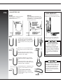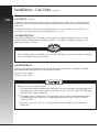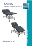
1
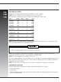
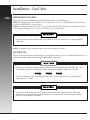
Installation – Electric Units
CSL
CSM
CSB
INTRODUCTION
This section provides the installation instructions for the Henny Penny Electric Combi-Steamers.
NOTE: The installation of this unit must conform to all local, state, and federal codes. In the absence of codes use
ANSI/NFPA No. 70-latest edition.
NOTE: Canadian installations must conform with the Canadian electrical code, C22.1, Part 1 and/or local codes.
X
Do Not puncture the cabinet with any objects such as drills or screws as electrical shock, or component
damage could result.
NOTE: The installation of this equipment should be performed by a qualified technician.
LOCATION
The proper location of the unit is very important for operation and convenience. Choose a location which will provide easy
loading and unloading without interfering with the final assembly of food orders.
NOTE: Adequate clearance must be provided for servicing and for operation.
Table Units:
Minimum clearances have to be maintained from the adjacent walls.
Right Side
Back Side
Left Side
CSB,CSM,CSL-6, 10, 1020 6” (150mm)
2” (50mm)
2” (50mm)
NOTE: 14” (350mm) is recommended at the left side of the unit for service purposes.
Place the combi-steamer on an original Henny Penny stand or on a level and sturdy surface. Recommended stand height
is 28.5” (725mm).
Minor unevenness of the surface/floor can be compensated by adjusting the legs of the stand or the appliance.
The weight of the units are as follows:
CSB, CSM, CSL-6
297 lbs.
(134.5 kg)
CSB, CSM, CSL-10
349 lbs.
(158.0 kg)
CSB, CSM, CSL-1020
507lbs.
(230.0 kg)
Installation planning should encourage sufficient space to keep the transport trolley/mobile rack at the left-hand side
of the unit.
NOTE: Ventilation must conform to local, state and national codes. Consult your local fire department or building authorities.
X
When moving the unit with a pallet jack ensure it is located under the 1-5/8” x 1-5/8” structure frame before
lifting the unit.
62
Installation – Electric Units (continued)
CSL
CSM
CSB
Floor Units:
NOTE: Adequate clearance must be provided for servicing and for operation.
Minimum clearances have to be maintained from the adjacent walls.
Right Side
Back Side
Left Side
CSB, CSM, CSL-20, 40
14” (350mm)
2” (50mm)
2” (50mm)
Place the combi-steamer on a level and sturdy surface. Minor unevenness of the surface/floor can be compensated by adjusting the legs of the appliance (+-15mm).
NOTE: The unit must be fixed to the floor to prevent moving when pushing oven racks into unit.
The oven rack must be positioned vertically in the unit, not tilting.
For minor unevenness in floor, the oven rack can be leveled using the optional leveling device. If necessary, construct ramps to level floor in front of units.
The weights of the units are as follows:
CSB, CSM, CSL-20 764 lbs. (345.5 kg)
CSB, CSM, CSL-40 1066 lbs. (483.5 kg)
Installation planning should encourage sufficient space for an additional roll-in rack at the left-hand side of the
unit.(20 pan - 29”, 40 pan - 52”)
When moving the unit with a pallet jack, ensure it is located under the 1-5/8” x 1-5/8” structuring frame before lifting unit.
Do Not support the unit at the service door. Damage to the unit will result.
63
CSL
CSM
CSB
ELECTRICAL SUPPLY
Standard electrical supply for all Combi-Steamers is 208-240 volt, 3 phase, 50-60 Hz.
NOTE: The power connections are located behind the service door (see section 5-3).
Each unit requires a separate fused service according to the following table: (3 phase only)
Model
Voltage
Phase
Amps
Load
CSL/M/B-6
CSL/M/B-6
CSL/M/B-6
CSL/M/B-6
208V
208V
240V
240V
3
1
3
1
27
46
27
40
9.6KW
9.6KW
9.6KW
9.6KW
CSL/M/B-10
CSL/M/B-10
208V
240V
3
3
52
45
18.6KW
18.6KW
CSL/M/B-1020
CSL/M/B-1020
208V
240V
3
3
88
76
31.5KW
31.5KW
CSL/M/B-20
CSL/M/B-20
208V
240V
3
3
103
90
37.2KW
37.2KW
CSL/M/B-40
CSL/M/B-40
208V
240V
3
3
175
152
63KW
63KW
NOTE: When the oven is installed it must be electrically grounded in accordance with local codes, or in the absence of local
codes, with the National Electric Code, ANSI/NFPA 70-1990.
Do Not use conduit as a supply ground, or electrical shock could result.
NOTE: All connections must comply with the oven data plate. A separate fused disconnect switch or circuit breaker
(not furnished) MUST be installed in the electrical supply line FOR EACH OVEN!
NOTE: The electrical diagram is located behind the service door.
The electric supply terminal block, located behind the service door, is clipped on a mounting rail which is attached to the
frame of the unit. The three phases of the power cord are connected to the three gray colored terminals. Ground is connected to the yellow-green terminal.
NOTE: The phase sequence does not have to be observed because of the automatic reversing action of the fan motor.
CHANGES IN VOLTAGE
To change voltages of the Combi-Steamers (ex: 208 to 240 volt) the following has to be changed:
1) Air and steam elements
2) Contactor LS5
3) CSM and CSL units - the wires on the control panel transformer and the interior light transformer must be switched to
the correct voltage terminals.
64
Installation – Electric Units (continued)
CSL
CSM
CSB
WATER SUPPLY
The Combi-Steamer should only be connected to a cold water supply which meets the quality requirements by the
EPA on drinking water. Soft water must be at least 5 or 6 grains.
The recommended water supply pressure is 44 psi, but 22 to 87 psi will work.
Should the water pressure exceed 87 psi, a pressure regulator must be installed into the supply line or
damage to the unit could result.
The water connection is done on a 3/4” NPT thread fitting, and a manual shut off valve must be installed between
the main cold water supply and the units supply line.
A minimum water conductivity of 20 micro Siemens is required for proper operation. If below this figure
the steam generator will over-fill.
NOTE: A check valve is built into the unit to prevent backflow.
DRAIN CONNECTION
The Combi-Steamer is to be installed to comply with the applicable Federal, State, or local plumbing codes.
The unit has an integrated vented drain system which acts as a reverse flow check valve, so it may be connected
directly with a P-trap to the drain system.
The drain must have a constant slope and a diameter of 2 inches over its entire length to ensure sufficient
discharge during Auto Flush from the steam generator, which is 3/4 quarts per second.
The drain must be steam temperature resistant pipe, which average drain temperature is 150°F (65°C).
No hose should be used.
65
Installation – Gas Units
CSG
INSTALLATION GAS UNITS
This section provides the installation instructions for the Henny Penny Gas Combi-Steamers
NOTE: The installation must conform with local codes or in the absence of local codes, with ANSI Z223.1 latest edition and
electrical code ANSI/NFPA No. 70 latest edition.
NOTE: For Canadian installations it should be done in accordance with the CAN/CGA B149.1 or.2 installation code and/or
local code and the Canadian electrical code, Part 1, CSA C22.1 for the electrical features.
Do Not puncture the cabinet with any objects such as drills or screws as electrical shock, or component damage
could result.
NOTE: The installation of this equipment should be performed by a qualified technician.
LOCATION-CSG
The proper location of the unit is very important for operation and convenience. Choose a location which will provide easy
loading and unloading without interfering with the final assembly of food orders.
Adequate clearance must be considered during installation between the unit and combustible walls. Also, clearance should be provided for servicing and operation of the unit. The minimum clearances are as follows:
Right Side
Back Side
Left Side
14” (350mm)
4” (100mm)
4” (100mm)
Place the Combi-Steamer on an original Henny Penny stand or on a level and sturdy surface. Recommended
stand height is 22” (555mm).
Due to the size of the steam generator, the left side of the unit weighs more than the right side. This weight
difference must be compensated by placing the lifting device more towards the left side of the unit, or damage
to the unit or personal injury could result.
66
Installation – Gas Units (continued)
CSG
Minor unevenness of the surface/floor can be compensated by adjusting the metal legs of the stand or the
appliance. The weight of the units are as follows:
CSG-10 556 lbs. (252 Kg)
CSG-12 529 lbs. (240 Kg)
CSG-20 1015 lbs. (460 Kg)
Do Not obstruct the flow of combustion and ventilation air to and from the unit. DO NOT obstruct the
ventilation holes in the panels of the unit, as these provide the combustion air for the burner, or damage
to the unit could result.
VENTILATION-CSG
The gas Combi-Steamers all should be located with a provision for venting into an adequate exhaust hood or ventilation
system. We recommend you consult a local ventilation or heating company to help in designing an adequate system.
NOTE: Ventilation must conform to local, state, and national codes. Consult your local fire department or building
authorities.
Ventilation of CSG-12:
NOTE: The Combi-Steamer CSG-12 is not suitable for connection to Type B Gas Vent and must be installed under a
ventilation hood.
Your Henny Penny Combi-Steamer CSG-12 is shipped fully assembled. In a second smaller carton you will find a
draft hood which has to be assembled to the unit.
Ventilation of CSG-12 table top version:
The draft hood must be assembled over the two flue outlets at the back of the Combi-Steamer CSG-12.
Ventilation of CSG-12 stacked version:
The stacked version kit comprises two different draft hoods, one with a single outlet and the second with a double
outlet.
A flue riser completes the stacked version flue assembly. Fix the single outlet draft hood over the flue outlets of
the lower unit. Place the flue riser over the top flue collar of the draft hood. Attach the double outlet draft hood
over the flue outlets of the upper unit so that the flue riser projects into the lower opening of this draft hood.
Ventilation of CSG-10:
The draft hood must be installed over the flue risers on top of the Combi-Steamer CSG-10 when the flue gas is discharged via a Type B gas vent.
When the flue gas of a CSG-10 is discharged to a ventilation hood the draft hood will not be installed.
Ventilation of CSG-20:
The draft hood must be installed over the flue risers on top of the Combi-Steamer CSG-20 when the flue gas is discharged via Type B gas vent.
When the flue gas of a CSG-20 is discharged to a ventilation hood the draft hood will not be installed.
67
CSG
WATER SUPPLY-CSG
The Combi-Steamer should only be connected to a cold water supply which meets the quality requirements by the EPA on
drinking water. Soft water must be at least 5 or 6 grains.
The recommended water supply pressure is 44 psi, but 22 to 87 psi will work.
Should the water pressure exceed 87 psi, a pressure regulator must be installed into the supply line or damage to
the unit could result.
Both water and gas connections are 3/4” NPT fittings. Be sure to connect to proper pipe. Check label on unit for each.
The water connection is done on a 3/4” NPT thread fitting, and a manual shut-off valve must be installed between the main
cold water supply and the units supply line.
A minimum water conductivity of 20 micro Siemens is required for proper operation, If below this figure the
steam generator will over-fill.
NOTE: A check valve is built into the unit to prevent backflow.
DRAIN CONNECTION-CSG
The Combi-Steamer is to be installed to comply with the applicable Federal, State, or local plumbing codes.
The unit has an integrated vented drain system which acts as a reverse flow check valve, so it may be connected directly
with a P-trap to the drain system.
The drain must have a constant slope and a diameter of 2 inches over its entire length to ensure sufficient
discharge during Auto Flush from the steam generator, which is 3/4 quarts per second.
The drain must be steam temperature resistant pipe, which average drain temperature is 150°F (65°C). No hose
should be used.
68
Installation – Gas Units (continued)
CSG
ELECTRICAL SUPPLY-CSG
The gas Combi-Steamer requires 120 volt, single phase, 60 Hertz, 15 amp, 3 wire grounded service. The gas unit
is factory equipped with a grounded cord and plug.
DO NOT DISCONNECT THE GROUND PLUG. This unit MUST be adequately and safely grounded or
electrical shock could result. Refer to local electrical codes for correct grounding procedures or in
absence of local codes, with the National Electrical Code, ANSI Z223.1 latest edition and electrical code
ANSI/NFPA No. 70-1990 latest edition. In Canada, all electrical connections are to be made in accordance
with the CAN/CGA B149.1 or .2 installation code and/or local code and the Canadian electrical code,
Part 1, CSA C22.1.
Before connecting incoming power to the unit, no more than 120 volts should show at each leg to ground.
Connecting a high leg to the black lead of the unit will severly damage many electrical components in the
unit and void all warranties. Call your local electrician or electric power supply company.
NOTE: The unit will not function and the reset signal will stay on with the white wire connected to the live black wire
and the black connected to neutral. An electrical schematic is located behind the left side panel of unit. A separate
fused disconnect switch, or circuit breaker, must be installed for each unit.
GAS SUPPLY-CSG
The gas Combi-Steamer is factory available for either natural or propane gas. Check the data plate to determine
the proper gas supply requirements.
DO NOT attempt to use any gas other than that specified on the data plate. Conversion kits can be
installed by your distributor if required. Incorrect gas supply could result in a fire or explosion resulting
in severe injuries and/or property damage.
To avoid possible serious personal injury, the installation must conform with local codes, or in the
absence of local codes, with the National Fuel Gas Code, ANSI Z223.1-1988 or latest edition. In Canada,
CAN/CGA-B 149.1 Natural Gas Installation Code CAN/CGA-B 149.2 Propane Installation Code.
All Henny Penny Combi-Steamers are equipped with two heat exchanger systems. One is responsible for steam
production, the second for convection heat. Each individual heat exchanger is heated with a separate burner
assembly.
69
CSG
GAS SUPPLY-CSG
CABLE RESTRAINT
RIGHT
WRONG
MINIMUM PULL of equipment away from
wall permissible for accessibility to
Quick Disconnect Device
AVOID SHARP BENDS AND KINKS when
pulling equipment away from wall. (Maximum
pull will kink ends, even if installed properly,
and reduce Connector life.)
Couplings and hose should be installed in
the same plane as shown at left. DO NOT
OFFSET COUPLINGS – this causes torsional
twisting and undue strain causing premature
failure.
Please refer to the illustration below when
installing cable restraint on all moveable units.
I-bolt is to be secured to the building using
acceptable building construction practices.
DRYWALL CONSTRUCTION
This is the correct way to install metal hose
for vertical travers. Note the single, natural
loop.
Allowing a sharp bend, as shown at right,
strains and twists the metal hose to a point of
early failure at the coupling.
Secure I-bolt to a building stud.
DO NOT attach to drywall only. Also,
locate the I-bolt at the same height as
the gas service. Preferred installation is
approximately six inches to either side
of service. Cable restraint must be at
least six inches shorter than flexible
gas line.
Maintain the minimum or larger bending
diameter between the couplings for longest
life.
Closing in the diameter at the couplings, as
shown at right, creates double bends causing
work fatigue failure of the fittings.
In all installations where “self-draining” is not
necessary, connect metal hose in a vertical
loop.
DO NOT CONNECT METAL HOSE
HORIZONTALLY...unless “self-draining”
is necessary then use support on lower plane
as shown at left.
70
Utilize elbows when necessary to avoid
sharp kinks or excessive bending. For
ease of movement, install with a “lazy”
loop. Gas appliance must be disconnected prior to maximum movement.
(Minimum movement is permissible for
hose disconnection.)
Installation – Gas Units (continued)
CSG
GAS SUPPLY (continued)
A steam burner gas valve and dry heat burner gas valve respectively are responsible for the gas supply to the individual burners. The Combi-Steamer models CSG have manual shut-off valves, that can be reached from the front
without tools.
The manual shut-off valves of these units are located behind the service cover under the operator panel. To operate the valves, unscrew the 2 knurled screws and pull the service cover off.
GAS LEAK TEST-CSG
After the piping and fittings have been installed, check for gas leaks. A simple checking method is to turn on the
gas and brush all connections with a soap solution. If bubbles occur, it indicates escaping gas. In this event, the
piping connection must be redone.
Never use a lighted match or open flame to test for gas leaks. Escaping gas could cause an explosion resulting in
severe personal injury and/or property damage.
GAS PRESSURE-CS
The gas pressure should be measured when all other gas appliances in the kitchen are on high flame. The minimum and maximum incoming line flow pressures should be as follows:
Natural: 7-11” water column
Propane: 11” water column
During pressure testing note the following:
1. The Combi-Steamer and its individual shut-off valve must be disconnected from the gas supply piping system
during any pressure testing of that system at test pressure in excess of 1/2 psig (3.45 kPa). Turn OFF main
gas shut-off valve or main gas supply line.
2. The appliance must be isolated from the gas supply piping system by closing its individual manual shut-off
valve during any pressure testing of the gas supply piping system at test pressure equal to or less than
1/2 psig (3.45 kPa).
3. If incoming w.c pressure is over 14” w.c. a separate regulator must be installed before the manual gas
shut-off valve.
71
CSG
TO PREVENT DAMAGE TO THE CONTROL VALVE REGULATOR DURING INITIAL TURN ON OF GAS IT IS
VERY IMPORTANT TO OPEN MANUAL SHUT-OFF VALVE VERY SLOWLY.
NOTE: After turning on the gas, the manual shut-off valve must remain open, except during pressure testing as outlined in the
above steps, or when necessary during service maintenance.
This incoming pressure reading can be taken by installing a gas pressure gauge on the front of the unit’s main gas valves
test port. This should be done with all gas appliances in operation on the same gas supply line. Should the manifold pressure drop below the desired level, consult your local gas utility service.
72