1
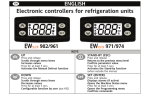
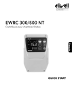
Henny Penny
Model CMC/CMR-103,104,105,106,107
SECTION 3. OPERATION
3-1.
INTRODUCTION
This section provides explanations of all controls, along
with operating procedures and daily maintenance. Read the
Introduction, Installation and Opeation Sections before
operating the unit.
Wait at least 4 hours before plugging the unit into an
electrical supply. The gases and oils in the refrigeration
system needs to settle before operating the compressor, or
damage to the compressor could result.
3-2.
OPERATING CONTROLS
Refer to figure 3-1.
Fig.
No.
Item
No.
Description
Function
3-1
1
Power Switch
Turns electrical power off and on to the unit; located on the
bottom of the control panel
3-1
2
Digital Display
Shows the temperatures and the information in the Technical
Mode
3-1
3
Used to increase setpoint values, as well as programming
values; also, automatic defrost cycles are programmed in
the controls, but to manually start a defrost cycle, press and
hold
for 3 seconds to start a manual defrost cycle;
“DEF/SET’ shows in display
3-1
4
Used to decrease setpoint values, as well as programming
values
3-1
5
Press to view the setpoint temperature, or hold it for it for 4
seconds to enter the program mode; once in the Program
Mode, press
to view other parameter setpoints;
Press
, along with
parameters
3-1
and
to change the
303
Henny Penny
3-2.
Model CMC/CMR-103,104,105,106,107
OPERATING CONTROLS
(Continued)
3
2
1
Figure 3-1
4
303
5
3-2
Henny Penny
3-3.
BASIC OPERATION
Model CMC/CMR-103,104,105,106,107
1.
Turn power switch to ON position.
2.
Wait for temperature to reach operating temperature,
34 to 38° F (1.1 to 3.3° C).
3.
Place chilled product into case.
Do not block the air return and air discharge vents with
product. Product temperatures may become unsafe,
and increase operating costs.
Do not use mechanical devices or other means to quicken
the defrosting process, other than those recommended by
the manufacturer, or damage to the unit could result.
Do not use electrical appliances inside the food storage
areas of the unit, unless they are of the type recommended
by the manufacturer, or damage to the unit could result.
3-4.
CLEANING
Weekly:
1. Remove all electrical power supplied to the unit by unplugging the power cord from the wall, or by turning off the
wall circuit breaker.
2. Clean interior and exterior surfaces with a soft cloth, soap and
water.
Do not use steel wool, other abrasive cleaners or
cleaners/sanitizers containing chlorine, bromine, iodine
or ammonia chemicals, as these will deteriorate the
stainless steel, and glass material, and shorten the life of
the unit.
Do not use a water jet (pressure sprayer) to clean the
unit, or component failure could result.
3. Clean around the electronic controls with a soft, damp cloth.
4. Reconnect the electrical power, and unit is now ready for
operation.
3-3
303
Henny Penny
3-4.
CLEANING
(Continued)
Model CMC/CMR-103,104,105,106,107
Every 3 Months:
1. Remove all electrical power supplied to the unit by unplugging
the power cord from the wall, or by turning off the wall circuit
breaker.
2. Remove all product from the unit.
3. Remove the riser and trays from the unit and clean with
soap and water at a sink.
4. Clean interior surfaces with a soft cloth, soap and water.
Do not use steel wool, other abrasive cleaners or
cleaners/sanitizers containing chlorine, bromine, iodine
or ammonia chemicals, as these will deteriorate the
stainless steel, and glass material, and shorten the life of
the unit.
Do not use a water jet (pressure sprayer) to clean the
unit, or component failure could result.
5. Clean around light fixtures with a soft, damp cloth.
6. Reconnect the electrical power, and unit is now ready for
operation.
If the power cord is damaged, have a qualified service
technician replace it to prevent electrical shock or
property damage.
303
3-4
Henny Penny
3-5.
PROGRAMMING
Model CMC/CMR-103,104,105,106,107
1. Press and hold
for 4 seconds. The “DEF/SET” light
flashes in display.
Temperature Setpoint
2. Press the
or
to change the temperature setpoint,
within 5 seconds. After 5 seconds, the last entered setpoint
stays in memory.
Other Parameters
3. Press
to access the other parameters. Each press of the
accesses the next parameter. The parameters are:
d: differential (-15...15 range)
LS: lower set; lower user-access setpoint limit
(-55...99 range)
The units are programmed to defrost 3 times a day, at 8 hour
intervals, lasting 30 minutes. Do not program the setpoint
temperature below 33° F (1° C), or ice build-up will decrease
efficiency.
HS: higher set; upper user-access setpoint limit
(-55...99 range)
CA: calibration; temperature readout offset to allow for
possible error due to probe location (-15...15 range)
rP: relay protection; select relay status in case of probe defect.
“on” = compressor on in case of probe defect.
“of” = compressor off in case of probe defect
PS: protection system-short cycle; select type of compressor
protection desired (the actual time delay is set with the next
parameter):
“0”=delay before start - in seconds;
“1”=delay before start - in minutes;
“2”=delay after stop - in minutes;
“3”=delay between starts - in minutes
Pt: protection time; select the time delay setting for compressor protection. (0...31 range)
3-5
303
Henny Penny
3-5.
PROGRAMMING
Continued
Model CMC/CMR-103,104,105,106,107
dS: defrost system (computation); dF=digifrost Feature;
defrost start time based on total compressor running time
rt=real time; defrost start frequency, based on real time
dI: defrost interval; defrost frequency in hours, based on the
selection of “dS”
dE: defrost endurance; total (maximum) length of a defrost
cycle, expressed in minutes. (1...99 range)
dL: display lock; temperature display is locked during a
defrost cycle (0...31 range)
“n”=no (readout continues to display the actual temperature, even during a defrost cycle
“y”=yes (readout is locked)
dr: display read-out; select the type of visualization in case of
temperature display lock during defrost (see prameter dL);
“C”=the temperature displayed at the start of a defrost is
locked and does not change during this cycle;
“dF”=during the defrost “dF” is displayed.
do: defrost at power on; selects whether or not, the system
goes through the defrost cycle at start-up (or after power
failure)
“n”=no; “y”=yes
dd: defrost delay at power on; delay of defrost cycle, in
minutes (0...99 range)
Error Code “E1”
This is the only error code in these controls. It indicates a temperature sensor failure, such as, a shorted sensor, a sensor break, or
absence of sensor.
It can also indicate an under-range in the system temperature (-55).
In case of an over-range in the system temperature, “99” shows first
in the display, followed by “E1”.
303
3-6
Henny Penny
3-6.
FLUORESCENT BULB
REPLACEMENT
Model CMC/CMR-103,104,105,106,107
UL Units
1. Pull the bulb out of the sockets.
2. Remove the bulb guard caps.
3. Install new fluorescent bulb in reverse order.
CE Units
1. Remove the bulb cover.
2. Rotate the bulb.
3. Pull the lamp out of the sockets.
4. Install new fluorescent lamp in reverse order.
3-7
1102