1
REFRIGERA TION SYSTEM S
Electronic controllers for refrigeration units
Environmentally
Optimised
Versatile high-performance controllers with
new energy saving algorithms for plug-in
refrigerated cabinets.
USER
MANUAL
Contents
INTRODUCTION....................................................................................5
MAIN FEATURES..................................................................................................................5
MODELS.............................................................................................................................5
DESCRIPTION.....................................................................................................................5
TECHNICAL SPECIFICATIONS..............................................................6
TECHNICAL SPECIFICATIONS (EN 60730-2-9)........................................................................6
FURTHER INFORMATION......................................................................................................6
Input Characteristics................................................................................................................................................. 6
Output Characteristics............................................................................................................................................... 6
Mechanical Characteristics....................................................................................................................................... 6
Regulations.................................................................................................................................................................. 6
CONNECTIONS...................................................................................................................7
EWPLUS 961 EO CONNECTIONS......................................................................................................................................... 7
EWPLUS 971 EO CONNECTIONS......................................................................................................................................... 7
EWPLUS 974 EO CONNECTIONS......................................................................................................................................... 7
APPLICATIONS.....................................................................................8
EWPlus 961 EO MODEL......................................................................................................8
APPLICATION 1................................................................................................................................................................. 8
APPLICATION 2................................................................................................................................................................. 8
APPLICATION 3................................................................................................................................................................. 9
APPLICATION 4................................................................................................................................................................. 9
EWPlus 971 EO MODEL....................................................................................................10
Application 1................................................................................................................................................................10
APPLICATION 2................................................................................................................................................................10
APPLICATION 3................................................................................................................................................................11
APPLICATION 4................................................................................................................................................................11
EWPlus 974 EO MODEL....................................................................................................12
APPLICATION 1................................................................................................................................................................12
APPLICATION 2................................................................................................................................................................12
APPLICATION 3................................................................................................................................................................13
APPLICATION 4................................................................................................................................................................13
USER INTERFACE AND START-UP.......................................................14
LED.................................................................................................................................14
KEYS................................................................................................................................15
PRELIMINARY CONFIGURATIONS........................................................................................16
SELECTING APPLICATIONS...............................................................................................................................................16
RESET PROCEDURE..........................................................................................................................................................16
MAIN PARAMETERS..........................................................................................................................................................16
SETPOINT: SETTING and EDIT LOCK.................................................................................................................................17
DISPLAY PROBES VALUE...................................................................................................................................................17
KEY-ACTIVATED FUNCTIONS.............................................................................................................................................17
FUNCTIONS AND REGULATORS..........................................................18
SETTINGS........................................................................................................................18
PROBE SETTING AND CALIBRATION...................................................................................................................................18
DISPLAY SETTINGS..........................................................................................................................................................18
EWPlus EO Family - Sommario
FUNCTIONS......................................................................................................................19
UPLOAD, DOWNLOAD, FORMATTING..................................................................................................................................19
COPY CARD...................................................................................................................................................................20
UNICARD......................................................................................................................................................................20
REGULATORS....................................................................................................................21
COMPRESSOR/GENERAL...................................................................................................................................................21
COMPRESSOR/GENERAL PROTECTIONS.............................................................................................................................22
Compressor safety timings..............................................................................................................................................23
DEFROST/COIL DRAINAGE...............................................................................................................................................24
Automatic defrost..........................................................................................................................................................25
Manual defrost..............................................................................................................................................................25
External defrost.............................................................................................................................................................26
1) Defrost with electrical heaters................................................................................................................................27
2) Defrost with compressor stopped...........................................................................................................................28
3) Cycle inversion defrost (hot gas)............................................................................................................................29
4) Defrost in FREE mode...........................................................................................................................................30
Alarm function during defrost..........................................................................................................................................30
Display function during defrost........................................................................................................................................30
FANS..............................................................................................................................................................................31
Fan operation in thermostat control.................................................................................................................................31
Fan operation in Duty Cycle mode....................................................................................................................................32
Fan operation during defrost...........................................................................................................................................32
Fan operation without probe............................................................................................................................................33
Fan operation during coil drainage...................................................................................................................................34
Post-ventilation..............................................................................................................................................................34
AUXILIARY OUTPUT (AUX/LIGHT)......................................................................................................................................35
PRESSURE SWITCH..........................................................................................................................................................36
DEEP COOLING CYCLE (DCC)............................................................................................................................................37
ENERGY SAVING..............................................................................................................................................................39
BOTTLE COOLER OPEN FRONT........................................................................................................................................40
BOTTLE COOLER GLASS DOOR........................................................................................................................................41
VERTICAL DISPLAY CABINET WITH DOOR........................................................................................................................42
COOL PROTECTION..........................................................................................................................................................43
CONDENSER FANS...........................................................................................................................................................44
CHECK VALVE..................................................................................................................................................................45
DOOR SWITCH INPUT......................................................................................................................................................46
STANDBY........................................................................................................................................................................46
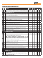
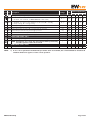
PARAMETER TABLE.............................................................................47
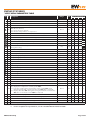
EWPlus 961 TABLES.........................................................................................................47
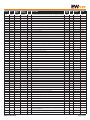
"USER" MENU PARAMETERS TABLE....................................................................................................................................47
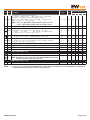
"INSTALLER" MENU PARAMETERS TABLE............................................................................................................................48
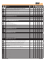
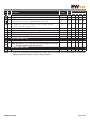
EWPlus 971 TABLES.........................................................................................................52
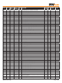
"USER" MENU PARAMETERS TABLE....................................................................................................................................52
"INSTALLER" MENU PARAMETERS TABLE............................................................................................................................53
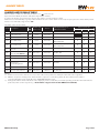
EWPlus 974 TABLES.........................................................................................................58
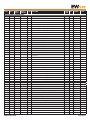
"USER" MENU PARAMETERS TABLE....................................................................................................................................58
"INSTALLER" MENU PARAMETERS TABLE............................................................................................................................59
EWPlus EO Family - Sommario
ALARMS TABLES.................................................................................64
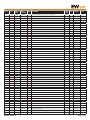
ALARMS AND SIGNALS TABLE............................................................................................64
DESCRIPTION OF ALARMS.................................................................................................66
Probe alarm.................................................................................................................................................................66
MINIMUM AND MAXIMUM TEMPERATURE alarm.................................................................................................................67
DEFROST alarm.............................................................................................................................................................68
ALARM SIGNALLING DEROST END DUE TO TIMEOUT.........................................................................................................68
EXTERNAL alarm............................................................................................................................................................68
DOOR OPEN alarm.........................................................................................................................................................69
COMPRESSOR OVERHEATING alarm.................................................................................................................................69
MODBUS MSK442 FUNCTIONS AND RESOURCES...............................70
DATA FORMAT (RTU)..........................................................................................................70
NETWORK........................................................................................................................70
MODBUS COMMANDS AVAILABLE AND DATA AREAS.............................................................71
ADDRESS CONFIGURATION................................................................................................71
PARAMETER VISIBILITY AND VALUES..................................................................................72
PARAMETER/VISIBILITY TABLE AND CLIENT TABLE...............................................................72
Parameter table...........................................................................................................................................................74
Folder visibility table................................................................................................................................................84
Client Table.................................................................................................................................................................84
WARNINGS.........................................................................................85
ELECTRICAL CONNECTIONS...............................................................................................85
DISCLAIMER.....................................................................................................................85
LIABILITY AND RESIDUAL RISKS........................................................................................85
CONDITIONS OF USE........................................................................................................85
EWPlus EO Family - Sommario
INTRODUCTION
The NEW EWPlus EO family of devices consists of electronic microprocessor controllers developed for the management of
plug-in refrigerated cabinets. It stands out for its performance and flexibility, thanks to energy saving algorithms and compressor
management.
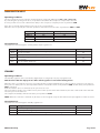
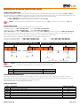
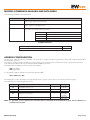
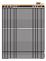
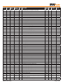
MAIN FEATURES
The following table lists the main features of models in the EWPlus EO family.
Feature
4-key keypad
Setpoint edit lock to prevent tampering
Password controlled access to configuration parameters
Display range
Configurable decimal point
Configurable °C/°F display
LEDs present on display
Defrost:
end defrost by timeout
end defrost by temperature
Number of analogue inputs for NTC probes
Analogue inputs Pb3 / Digital input D.I.1
Digital input D.I.2
Display probe 3
Relay outputs (*)
Relay ratings
TTL for connection to Copy Card
Buzzer
Quick fitting to panel using brackets
MODEL
EWPlus 961 EO
EWPlus 974 EO
EWPlus 971 EO
NTC: -50.0°C ... +110°C
(*)
1
1
1
2
1
1
2
1
1
2Hp
2Hp + 8A
Optional (*)
2Hp + 8A + 5A
(*) refer to the label on the device
IMPORTANT: each feature must always be verified with the model available.
MODELS
The 3 models in the EWPlus EO family differ in terms of the number of inputs and outputs and, more particularly:
- EWPlus 961 EO: 1 analogue input, 1 digital/analogue input, 1 digital input and 1 relay output (2 Hp)
- EWPlus 971 EO: 2 analogue inputs, 1 digital/analogue input, 1 digital input and 2 relay outputs (2 Hp+8A)
- EWPlus 974 EO: 2 analogue inputs, 1 digital/analogue input, 1 digital input and 3 relay outputs (2 Hp+8A+5A)
DESCRIPTION
These are new-generation devices with one or two activation points developed for the management of plug-in refrigerated cabinets.
They have one, two or three relay outputs, one or two sensors for temperature regulation and/or defrost, a multifunctional Digital/
Temperature input and a digital input.
Outputs A, B and C can be used to control:
- compressor
- defrosting elements
- evaporator fans
- alarm
- AUX output
- standby
- reversal of condenser fans direction
- activation of check valve
The Digital inputs (D.I.1 and D.I.2) can be used for:
- defrost activation
- reduced setpoint
- AUX management
- door switch
- external alarm
- standby (ON/OFF)
- pressure switch
- deep cooling
- Energy Saving
- door switch + Energy Saving
EWPlus EO Family
Pag. 5/86
TECHNICAL SPECIFICATIONS
TECHNICAL SPECIFICATIONS (EN 60730-2-9)
Classification:
Mounting:
Type of action:
Pollution class:
Material class:
Overvoltage category:
Nominal pulse voltage:
Temperature:
Power supply:
Power consumption:
Digital outputs (relay):
Fire resistance category:
Software class:
operating (not safety) device for incorporation
panel mounting with 71x29 mm (+0.2/-0.1 mm) drilling template
1.B
2
IIIa
II
2500V
Use: –5 … +55 °C - Storage: -30 … +85 °C
230Va (±10%) 50/60 Hz
4.5W max
refer to the label on the device
D
A
NOTE: check the power supply rating on the device’s label; contact our Sales Office for power and relay ratings.
FURTHER INFORMATION
Input Characteristics
Display range:
Accuracy:
Resolution:
Buzzer:
Analogue Inputs:
Digital Inputs:
NTC: -50.0°C ... +110°C (on 3-digit display with +/- sign)
Better than 0.5% of full-scale +1 digit
0.1 °C
YES (depends on model)
1 NTC (EWPlus 961 EO) or 2 NTC (EWPlus 971/974 EO)
2 voltage-free digital inputs (D.I.1 and D.I.2)
NOTES: - D.I.1 can also be configured as a probe input (H11=0 and H43=y)
- D.I.2, if activated, should be connected to terminals 1-2 of the TTL connector (H12 ≠ 0)
Output Characteristics
Digital Outputs:
EWPlus 961 EO: 1 Compressor relay: UL60730 (A)
UL60730 (A)
12(8) A max 250Va
2Hp (12FLA - 72LRA) max 240Va
EWPlus 971 EO: 1 Compressor relay: UL60730 (A)
12(8) A max 250Va
UL60730 (A)
2Hp (12FLA - 72LRA) max 240Va
1 AUX relay:
N.O. 8(4)A - N.C. 6(3)A max 250Va
EWPlus 974 EO: 1 Compressor relay:
1 Fan relay:
1 AUX relay:
UL60730 (A)
12(8) A max 250Va
UL60730 (A)
2Hp (12FLA - 72LRA) max 240Va
N.O. 8(4)A - N.C. 6(3)A max 250Va
5(2)A max 250Va
Mechanical Characteristics
Housing:
Dimensions:
Terminals:
Connectors:
Humidity:
PC+ABS UL94 V-0 resin casing, polycarbonate window, thermoplastic resin keys
front 74x32 mm, depth 59 mm (without terminals)
screw-on/removable for cables with cross-section of 2.5mm2
TTL for connection to Copy Card + D.I.2
Usage / Storage: 10...90% RH (non-condensing)
Regulations
Electromagnetic compatibility:
The device complies with Directive 2004/108/EC
Safety:
The device complies with Directive 2006/95/EC
Food Safety:
The device complies with standard EN 13485 as follows:
- suitable for storage
- climate range A
- measurement class 1 in the range from -35°C to 25°C (*)
(* exclusively using Eliwell NTC probes)
NOTE:The technical specifications stated in this document regarding measurement (range, accuracy, resolution, etc.) refer strictly
to the instrument and not to any accessories provided, such as the probes.
This means, for example, that the error introduced by the probe must be added to the error of the instrument.
EWPlus EO Family
Pag. 6/86
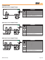
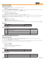
CONNECTIONS
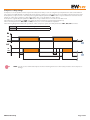
EWPLUS 961 EO CONNECTIONS
EWPLUS 961
TERMINALS
TTL
(A)
D.I.2
A
230Va (±10%)
4.5W
3-4
230Va power supply input
N-L
230Va power supply
9-10
9 10 11
2 3 4
2-3: Compressor relay
TTL
Pb3
D.I.1
Pb1
11-10
Probe Pb1
Digital Input 1 (H11 ≠ 0 and H43 = n) or
Probe Pb3 (H11 = 0 and H43 = y)
TTL Input or Digital Input 2 (H12 ≠ 0)
N
L
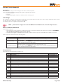
EWPLUS 971 EO CONNECTIONS
EWPLUS 971
TERMINALS
TTL
(B)
A
230Va (±10%)
4.5W
1-2: Compressor relay
D.I.2
3-4
230Va power supply input
N-L
230Va power supply
5-6: N.O. AUX relay
D.I.1
Pb2
Pb1
8 9 10 11
2 3 4 5 6 7
5-7: N.C. AUX relay
Pb3
(A)
N
L
8-10
Probe Pb2
9-10
Probe Pb1
11-10
TTL
Digital Input 1 (H11 ≠ 0 and H43 = n) or
Probe Pb3 (H11 = 0 and H43 = y)
TTL Input or Digital Input 2 (H12 ≠ 0)
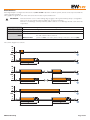
EWPLUS 974 EO CONNECTIONS
EWPLUS 974
TERMINALS
TTL
(C)
(A)
(B)
1-3: AUX relay
D.I.2
2-3: Compressor relay
A
230Va (±10%)
4.5W
8 9 10 11
1 2 3 4 5 6 7
3-4
230Va power supply input
N-L
230Va power supply
5-6: N.O. Fans relay
N
L
Pb3
D.I.1
Pb1
Pb2
5-7: N.C. Fans relay
8-10
Probe Pb2
9-10
Probe Pb1
11-10
TTL
EWPlus EO Family
Digital Input 1 (H11 ≠ 0 and H43 = n) or
Probe Pb3 (H11 = 0 and H43 = y)
TTL Input or Digital Input 2 (H12 ≠ 0)
Pag. 7/86
APPLICATIONS
EWPlus 961 EO MODEL
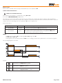
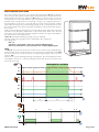
APPLICATION 1
The application is for "GLASS DOOR BOTTLE COOLERS" and the set configuration is as follows:
- Defrost end:
set by time (start delay (dOH) = 0 minutes, maximum duration (dEt) = 30 minutes)
- ACTIVE alarms:
max/min temperature alarm on Pb1 (HAL and LAL as a relative value)
- Analogue Inputs:
1 NTC input (environmental probe Pb1)
- Digital Input:
1 input set as "Door Switch + Energy Saving" (H11 = 10)
- Digital Outputs:
1 compressor relay:
UL60730 (A)
2Hp (12FLA - 72LRA) max 240Va or
UL60730-1 (A) 12(8)A max 250Va
- Key configuration:
UP key
= manual defrost
DOWN key
= not set
ESC key
= standby
APPLICATION
CONNECTION DIAGRAM
D.I.1
1€
1€
+
Pb1
Ambient
T.E.V.
Evaporator
Valve
Compressor
APPLICATION 2
The application is for "GLASS DOOR BOTTLE COOLERS" and the set configuration is as follows:
- Defrost end:
set by time (start delay (dOH) = 0 minutes, maximum duration (dEt) = 30 minutes)
- ACTIVE alarms: max/min temperature alarm on Pb1 (HAL and LAL as a relative value)
Compressor overheating alarm on Pb3
- Analogue Inputs:
1 NTC input (environmental probe Pb1)
- Digital Input:
1 NTC input (set as analogue which connects to Pb3 - H11=0 and H43=y)
- Digital Outputs:
1 compressor relay:
UL60730 (A)
2Hp (12FLA - 72LRA) max 240Va or
UL60730-1 (A) 12(8)A max 250Va
- Key configuration:
UP key
= manual defrost
DOWN key
= not set
ESC key
-= standby
APPLICATION
CONNECTION DIAGRAM
Pb1
Ambient
Pb3
T.E.V.
Valve
EWPlus EO Family
Evaporator
Compressor
Pag. 8/86
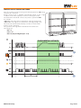
APPLICATION 3
The application is for "OPEN FRONT BOTTLE COOLERS" and the set configuration is as follows:
- Defrost end:
set by time (start delay (dOH) = 0 minutes, maximum duration (dEt) = 30 minutes)
- ACTIVE alarms:
max/min temperature alarm on Pb1 (HAL and LAL as a relative value)
- Analogue Inputs:
1 NTC input (environmental probe Pb1)
- Digital Input:
1 input set as "Energy Saving" (H11 = 9)
- Digital Outputs:
1 compressor relay:
UL60730 (A)
2Hp (12FLA - 72LRA) max 240Va or
UL60730-1 (A) 12(8)A max 250Va
- Key configuration:
UP key
= manual defrost
DOWN key
= not set
ESC key
= standby
APPLICATION
CONNECTION DIAGRAM
D.I.1
1€
1€
Pb1
Ambient
T.E.V.
Evaporator
Valve
Compressor
APPLICATION 4
The application is for "OPEN FRONT BOTTLE COOLERS" and the set configuration is as follows:
- Defrost end:
set by time (start delay (dOH) = 0 minutes, maximum duration (dEt) = 30 minutes)
- ACTIVE alarms:
max/min temperature alarm on Pb1 (HAL and LAL as a relative value)
- Analogue Inputs:
1 NTC input (environmental probe Pb1)
- Digital Input:
1 input set as "Energy Saving" (H11 = 9)
- Digital Outputs:
1 compressor relay:
UL60730 (A)
2Hp (12FLA - 72LRA) max 240Va or
UL60730-1 (A) 12(8)A max 250Va
- Key configuration:
UP key
= manual defrost
DOWN key
= not set
ESC key
= standby
APPLICATION
CONNECTION DIAGRAM
D.I.1
1€
1€
Pb1
Ambient
T.E.V.
Valve
EWPlus EO Family
Evaporator
Compressor
Pag. 9/86
EWPlus 971 EO MODEL
Application 1
The application is for "GLASS DOOR BOTTLE COOLERS" and the set configuration is as follows:
- Defrost end:
set by temperature (dSt = 8.0°C)
- ACTIVE alarms:
max/min temperature alarm on Pb1 (HAL and LAL as a relative value)
- Analogue Inputs:
2 NTC inputs (environmental probe Pb1 + evaporator probe Pb2)
- Digital Input:
1 input set as "Door Switch + Energy Saving" (H11 = 10)
- Digital Outputs:
1 AUX/light relay:
N.O. 8(4)A - N.C. 6(3)A max 250Va
1 compressor relay:
UL60730 (A)
2Hp (12FLA - 72LRA) max 240Va or
UL60730-1 (A) 12(8)A max 250Va
- Key configuration:
UP key
= manual defrost
DOWN key
= light/AUX activation
ESC key
= standby
APPLICATION
CONNECTION DIAGRAM
D.I.1
1€
1€
+
Pb1
Ambient
Pb2
T.E.V.
Evaporator
Valve
Compressor
APPLICATION 2
The application is for "OPEN FRONT BOTTLE COOLERS" and the set configuration is as follows:
- Defrost end:
set by temperature (dSt = 3.0°C)
- ACTIVE alarms:
max/min temperature alarm on Pb1 (HAL and LAL as an absolute value)
- Analogue Inputs:
2 NTC inputs (environmental probe Pb1 + evaporator probe Pb2)
- Digital Input:
1 input set as "Energy Saving" (H11 = 9)
- Digital Outputs:
1 AUX/light relay:
N.O. 8(4)A - N.C. 6(3)A max 250Va
1 compressor relay:
UL60730 (A)
2Hp (12FLA - 72LRA) max 240Va or
UL60730-1 (A) 12(8)A max 250Va
- Key configuration:
UP key
= manual defrost
DOWN key
= light/AUX activation
ESC key
= standby
APPLICATION
CONNECTION DIAGRAM
D.I.1
1€
1€
Pb1
Ambient
Pb2
T.E.V.
Valve
EWPlus EO Family
Evaporator
Compressor
Pag. 10/86
APPLICATION 3
The application is for "GLASS DOOR MERCHANDISERS" and the set configuration is as follows:
- Defrost end:
set by temperature (dSt = 8.0°C)
- ACTIVE alarms:
max/min temperature alarm on Pb1 (HAL and LAL as a relative value)
- Analogue Inputs:
2 NTC inputs (environmental probe Pb1 + evaporator probe Pb2)
- Digital Input:
1 input set as "Door Switch + Energy Saving" (H11 = 10)
- Digital Outputs:
1 defrost relay:
N.O. 8(4)A - N.C. 6(3)A max 250Va
1 compressor relay:
UL60730 (A)
2Hp (12FLA - 72LRA) max 240Va or
UL60730-1 (A) 12(8)A max 250Va
- Key configuration:
UP key
= manual defrost
DOWN key
= not set
ESC key
= standby
APPLICATION
CONNECTION DIAGRAM
D.I.1
1€
1€
+
Pb1
Ambient
Pb2
T.E.V.
Valve
Compressor
Evaporator
APPLICATION 4
The application is for "GLASS DOOR BOTTLE COOLERS" and the set configuration is as follows:
- Defrost end:
set by temperature (dSt = 8.0°C)
- ACTIVE alarms:
max/min temperature alarm on Pb1 (HAL and LAL as a relative value)
- Analogue Inputs:
2 NTC inputs (environmental probe Pb1 + evaporator probe Pb2)
- Digital Input:
1 input set as "Door Switch + Energy Saving" (H11 = 10)
- Digital Outputs:
1 fan relay:
N.O. 8(4)A - N.C. 6(3)A max 250Va
1 compressor relay:
UL60730 (A)
2Hp (12FLA - 72LRA) max 240Va or
UL60730-1 (A) 12(8)A max 250Va
- Key configuration:
UP key
= manual defrost
DOWN key
= not set
ESC key
= standby
APPLICATION
CONNECTION DIAGRAM
D.I.1
1€
1€
+
Pb1
Ambient
Pb2
T.E.V.
Valve
EWPlus EO Family
Evaporator
Compressor
Pag. 11/86
EWPlus 974 EO MODEL
APPLICATION 1
The application is for "GLASS DOOR BOTTLE COOLERS" and the set configuration is as follows:
- Defrost end:
set by temperature (dSt = 8.0°C)
- ACTIVE alarms:
max/min temperature alarm on Pb1 (HAL and LAL as a relative value)
- Analogue Inputs:
2 NTC inputs (environmental probe Pb1 + evaporator probe Pb2)
- Digital Input:
1 input set as "Door Switch + Energy Saving" (H11 = 10)
- Digital Outputs:
1 fan relay:
N.O. 8(4)A - N.C. 6(3)A max 250Va
1 compressor relay:
UL60730 (A)
2Hp (12FLA - 72LRA) max 240Va or
UL60730 (A)
12(12)A max 250Va
1 AUX/light relay:
5(2)A max 250Va
- Key configuration:
UP key
= manual defrost
DOWN key
= light/AUX activation
ESC key
= standby
APPLICATION
CONNECTION DIAGRAM
D.I.1
1€
1€
+
Pb1
Ambient
Pb2
T.E.V.
Evaporator
Valve
Compressor
APPLICATION 2
The application is for "OPEN FRONT BOTTLE COOLERS" and the set configuration is as follows:
- Defrost end:
set by temperature (dSt = 3.0°C)
- ACTIVE alarms:
max/min temperature alarm on Pb1 (HAL and LAL as an absolute value)
- Analogue Inputs:
2 NTC inputs (environmental probe Pb1 + evaporator probe Pb2)
- Digital Input:
1 input set as "Energy Saving" (H11 = 9)
- Digital Outputs:
1 fan relay:
N.O. 8(4)A - N.C. 6(3)A max 250Va
1 compressor relay:
UL60730 (A)
2Hp (12FLA - 72LRA) max 240Va or
UL60730 (A)
12(12)A max 250Va
1 AUX/light relay:
5(2)A max 250Va
- Key configuration:
UP key
= manual defrost
DOWN key
= light/AUX activation
ESC key
= standby
APPLICATION
CONNECTION DIAGRAM
D.I.1
1€
1€
Pb1
Ambient
Pb2
T.E.V.
Valve
EWPlus EO Family
Evaporator
Compressor
Pag. 12/86
APPLICATION 3
The application is for "GLASS DOOR MERCHANDISERS" and the set configuration is as follows:
- Defrost end:
set by temperature (dSt = 8.0°C)
- ACTIVE alarms:
max/min temperature alarm on Pb1 (HAL and LAL as a relative value)
- Analogue Inputs:
2 NTC inputs (environmental probe Pb1 + evaporator probe Pb2)
- Digital Input:
1 input set as "Door Switch + Energy Saving" (H11 = 10)
- Digital Outputs:
1 defrost relay: N.O. 8(4)A - N.C. 6(3)A max 250Va
1 compressor relay:
UL60730 (A)
2Hp (12FLA - 72LRA) max 240Va or
UL60730 (A)
12(12)A max 250Va
1 fan relay: 5(2)A max 250Va
- Key configuration:
UP key
= manual defrost
DOWN key
= not set
ESC key
= standby
APPLICATION
CONNECTION DIAGRAM
D.I.1
1€
1€
+
Pb1
Ambient
Pb2
T.E.V.
Valve
Evaporator
Compressor
APPLICATION 4
The application is for "OPEN FRONT BOTTLE COOLERS" and the set configuration is as follows:
- Defrost end:
set by temperature (dSt = 7.0°C)
- ACTIVE alarms:
max/min temperature alarm on Pb1 (HAL and LAL as a relative value)
- Analogue Inputs:
2 NTC inputs (environmental probe Pb1 + evaporator probe Pb2)
- Digital Input:
1 input set as "Energy Saving" (H11 = 9)
- Digital Outputs:
1 relay for reversing condenser fans:
N.O. 8(4)A - N.C. 6(3)A max 250Va
1 compressor relay:
UL60730 (A)
2Hp (12FLA - 72LRA) max 240Va or
UL60730 (A)
12(12)A max 250Va
1 AUX/light relay:
5(2)A max 250Va
- Key configuration:
UP key
= manual defrost
DOWN key
= light/AUX activation
ESC key
= standby
APPLICATION
CONNECTION DIAGRAM
D.I.1
1€
1€
Pb1
Ambient
Pb2
Evaporator
Compressor
EWPlus EO Family
Condenser
Pag. 13/86
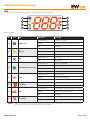
USER INTERFACE AND START-UP
LED
All instruments in the EWPlus EO family are equipped with the following display:
1
5
2
6
3
7
4
8
Meaning of LEDs:
No
Icon
Compressor
1
Defrost
2
3
Fans
Reduced SET / Economy
4
Alarm
5
6
°F readout
AUX
7
8
NOTE:
LED
°C readout
Operation
Meaning
Permanently on
compressor active
Blinking
delay, protection or start-up blocked
OFF
otherwise
Permanently on
defrost active
Blinking
activated manually or from Digital Input
OFF
otherwise
Permanently on
fans active
OFF
otherwise
Permanently on
Energy Saving ON
Blinking
reduced setpoint active
Rapid blinking
access to level2 parameters
OFF
otherwise
Permanently on
alarm present
Blinking
alarm acknowledged
OFF
otherwise
Permanently on
°F setting (dro =1)
OFF
otherwise
Permanently on
Aux output active (according to model)
Blinking
deep cooling cycle active
OFF
otherwise
Permanently on
°C setting (dro = 0)
OFF
otherwise
hen the instrument is powered on it performs a lamp test, during which time the display and LEDs will flash
W
for several seconds to check that they all function correctly.
EWPlus EO Family
Pag. 14/86
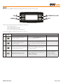
KEYS
All devices in the EWPlus family are equipped with 4 keys as shown in the picture:
UP 1
3 STAND-BY or ESC
DOWN 2
4 SET
Each key has a different function depending on whether it is:
- pressed and released
- pressed for at least 5 seconds
- pressed and held at start-up
- pressed in combination with another key
The following table summarises the function of each key:
No
Key
Press and release
Action
Press for at least 5 secs
Start-up
1
- Scrolls through menu items
- Increases values
- Activates the Manual Defrost function
(when outside the menus)
---
2
- Scrolls through menu items
- Decreases values
- Function can be configured by the user
(when outside the menus) (see parameter
H32)
---
3
- Returns to the previous menu level - Activates the Standby function (when
- Confirms parameter value
outside the menus)
4
set
- Displays any alarms (if active)
- Opens Machine Status menu
EWPlus EO Family
- Opens Programming menu (User and
Installer Parameters)
- Confirms commands
---
when pressed during
start-up it enables
the user to select the
application to be loaded.
Pag. 15/86
PRELIMINARY CONFIGURATIONS
After making the electrical connections, simply power up the device to start operation.
At first start-up, Eliwell recommends that you:
1) select the preset Application that most closely matches your own.
2) configure the main parameters, indicated in the USER menu, as per your requirements.
" icon off and labels E1, E2 and E3 not displayed).
3) make sure there are no active alarms ("
NOTE: E2 is only present on EWPlus 971/974 EO.
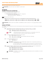
SELECTING APPLICATIONS
The procedure for loading one of the default applications is:
• at start-up of the device, keep the set key pressed: the label “AP1” will appear;
• browse the various applications (AP1-AP2-AP3-AP4) using the
and
keys;
•select the desired application using the set key (“AP3” in the example) or cancel the procedure by pressing the
alternatively wait for the timeout;
• if the operation is successful, the display will show "y", if not it will show "n";
• after a few seconds the instrument will return to the main display.
key;
Power-on + set
set
RESET PROCEDURE
EWPlus EO instruments can be RESET and the default factory settings restored in a simple and user-friendly way.
This is done by simply reloading one of the basic applications (see “Loading default applications”).
You may need to RESET the instrument in circumstances in which the normal operation of the instrument is compromised or if you
decide to restore the instrument to its default configuration (e.g. Application 1 values).
IMPORTANT!: This operation resets the instrument to its initial state, returning all the parameters to their default values.
This means that all changes made to operating parameters will be lost.
MAIN PARAMETERS
See USER menu table parameters for the various models.
EWPlus EO Family
Pag. 16/86
SETPOINT: SETTING and EDIT LOCK
To display the Setpoint value, press the set key and enter the "Machine Status" menu, then press the set key again when the “SEt”
label is displayed.
The Setpoint value appears on the display. To change the Setpoint value, press the
and
keys within 15 seconds.
Press set to confirm the modification.
set
set
set
It is possible to disable the keypad on this device.
The keypad can be locked by programming the “LOC” parameter.
With the keypad locked you can still access the “Machine Status” menu by pressing set to display the Setpoint, but you cannot edit it.
To disable the keypad lock, repeat the locking procedure.
DISPLAY PROBES VALUE
To display the value read from probes connected to the device, press the set key and enter the "Machine Status" menu, then press
the set key again when one of the probe-related labels “Pb1, Pb2 or Pb3” is displayed.
The value measured by the associated probe will appear on the display.
NOTES:
1) Pb2 is only present on EWPlus 971/974 EO models.
2) The displayed value is read-only and cannot be modified.
KEY-ACTIVATED FUNCTIONS
All models have the UP key set to activate the "Manual Defrost" function.
The DOWN and ESC keys can also be set to activate a specific user-defined function.
The parameters for configuring the two keys are:
• H32 = DOWN key configuration
• H33 = ESC key configuration
The values that can be set apply to both keys and the functions that can be activated are:
Temperature
value H32/H33
0
1
2
3
4
5
6
EWPlus EO Family
Functions that can be activated by model
EWPlus 961 EO
EWPlus 971 EO
EWPlus 974 EO
disabled
disabled
disabled
defrost
defrost
defrost
not used
aux
aux
reduced set
reduced set
reduced set
standby
standby
standby
deep cooling cycle
deep cooling cycle
deep cooling cycle
energy saving
energy saving
energy saving
Pag. 17/86
FUNCTIONS AND REGULATORS
This section describes the various functions of the devices.
IMPORTANT: the functions may not be available in certain models.
SETTINGS
PROBE SETTING AND CALIBRATION
Depending on the model, the devices are equipped with:
• 1 or 2 analogue inputs Pb1 and Pb2;
• 1 multifunctional analogue/digital input that can be configured as:
- Digital input (H11 ≠ 0 and H43 = n) or
- Analogue probe Pb3 (H11 = 0 and H43 = y).
ONLY NTC type probes can be used.
After installation, the values read by the probes can be corrected/calibrated using the following parameters:
• CA1: probe 1 offset. Positive or negative value to be added to the value read by Pb1 (Range: -12.0 ... +12.0)
• CA2: probe 2 offset. Positive or negative value to be added to the value read by Pb2 (Range: -12.0 ... +12.0)
• CA3: probe 3 offset. Positive or negative value to be added to the value read by Pb3 (Range: -12.0 ... +12.0)
IMPORTANT: parameter CA2 is not available in model EWPlus 961 EO since this device is not equipped with probe Pb2.
DISPLAY SETTINGS
Folder "diS" contains the parameters used to set the temperature readout, decimal point usage, unit of measurement and display
during defrost.
• ndt: enables/disables decimal point display (with resolution of one-tenth of a degree; e.g.: 10.0°C)
Display with decimal point is only possible within the range of values from -99.9°C to +99.9°C
• ndt = y displays read values with decimal point
• ndt = n displays read values without decimal point
NOTE:enabling/disabling the decimal point only affects the on-screen display of values. The
controller will continue to perform calculations with the decimal point.
• ddL: sets the type of display during and up to the end of defrost
• ddL = 0 displays the value of Pb1
• ddL = 1 continues to display the value read by Pb1 at the start of defrosting
• ddL = 2 displays fixed label "dEF"
• dro: sets temperature display to °C or °F.
• dro = 0 display in °C
• dro = 1 display in °F
! IMPORTANT: switching between °C and °F DOES NOT modify the values of temperature parameters (e.g.
set=10°C becomes 10°F).
This means that the maximum and minimum limits of the parameters as an absolute value are
the same for both units of measurement and the ranges are therefore different from each other.
• ddd:determines whether to display the value of the Setpoint, probe Pb1, probe Pb2 or the value of multifunctional
(analogue or digital) input Pb3. All other display and adjustment modes are the same.
• ddL = 0 displays the Setpoint value
• ddd = 1 displays the values read by Pb1
• ddd = 2 displays the values read by Pb2
• ddd = 3 displays the values read by Pb3
!
EWPlus EO Family
IMPORTANT:model EWPlus 961 EO is not equipped with probe Pb2 therefore the value ddd= 2 is not used
and must not be set.
Pag. 18/86
FUNCTIONS
UPLOAD, DOWNLOAD, FORMATTING
Description
The Unicard/Copy Card must be connected to the TTL serial port and allows the rapid programming of instrument parameters.
OWNLOAD From Reset Only operating mode: at power-on, if the Unicard/Copy Card is inserted in the device, the
D
controller automatically downloads data.
After connecting the Unicard/Copy Card with the device switched off and at the end of the lamp test, one of the following labels will
be displayed:
• dLY if the operation was successful
• dLn if the operation was not successful
After about 5 seconds, the display will display the probe or setpoint value, depending on the default settings.
IMPORTANT: once download has been completed successfully, the controller will start to work with the new map loaded.
Operating mode: access “Installer” parameters by entering the password “PA2” if enabled (PA2≠0), scroll through the folders using
and
until folder "FPr" appears. Select it using set , scroll through the parameters using
and
and finally select
one of the functions by pressing set :
• UL (Upload):This function uploads the programming parameters from the instrument to the card.
If the operation is successful, the display will show “y”, otherwise it will show “n”.
• Fr (Format):This command is used to format the copy card (which is necessary when using the card for the first time).
Important: the Fr parameter deletes all data present and this operation cannot be reversed.
• Download:Connect the Unicard/Copy Card with the instrument switched off. At power-on, data will automatically start
downloading from the Unicard/Copy Card to the instrument. At the end of the lamp test, the display will show
“dLy” if the operation was successful and “dLn” if not.
DOWNLOAD
OR
UPLOAD
User parameters
The parameters that control this function are:
Label
Description
Model
UL
Transfer programming parameters from instrument to Copy Card
All
Fr
Format Copy Card. Erases all data contained in the Copy Card.
All
EWPlus EO Family
Pag. 19/86
COPY CARD
The Copy Card can be used to download/upload a parameter map from/to a controller.
Depending on whether the parameter map is being uploaded or downloaded, the controller must be powered on or in the process
of starting up.
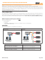
UNICARD
The Unicard, like the Copy Card, can be used to download/upload a parameter map from/to a controller.
Its flexibility enables the various devices to be customised quickly and simply.
The main features that distinguish it from the Copy Card are:
• 1): it can be connected directly to the computer via USB
• 2): it can be powered by means of a USB power supply and can directly power the controller during upload/download.
The Unicard power supply options are as follows:
A) Chiller power supply
0110 011010100111010100010101
UNICARD power supply
UNICARD
Controller
B) Field power supply
0110 01101010011101010001010
1
UNICARD
Controller
Controller Power Supply
0110 01101010011101010001010
1
UNICARD power supply
EWPlus EO Family
UNICARD
Controller
Pag. 20/86
REGULATORS
COMPRESSOR/GENERAL
Description
The compressor is controlled by the device's relay. It will be switched on or off depending on:
• the temperature status readings from probe Pb1
• the temperature control functions set
• the defrost/coil drainage functions (see Defrost section)
See the wiring diagrams for details of how to connect the compressor to the device.
The polarity of the relay is fixed and is NOT configurable.
When an offset is activated (parameter OSP) from function or from digital input, the SEt value is replaced by the value Set+OSP
taking into account the sign of OSP.
This condition of replacing SEt with the value Set+OSP is saved in the controller's non-volatile memory hence when power returns
after a blackout, the device will restart in the state that was active prior to the blackout.
NOTE: digital output 1 is always set as "Compressor".
Operating conditions
The regulator is activated provided that:
• the device is ON
• there is not a control probe fault alarm "E1"
• the time set in parameter OdO has elapsed (if OdO≠0)
• a defrost cycle is not underway (except in FREE mode)
• there is no External Alarm blocking the compressor
• there is no Overheating alarm on probe Pb3 (when H11 = 0 and H43 ≠ 0)
(There is a fixed interval of one second between the request and activation of the relay)
The diagrams below indicate the compressor activation mode for heating/cooling based on parameters SEt and diF > 0:
ON
OFF
°C
diF
SET
(SET + diF)
(Pb1)
User parameters
The parameters that manage this regulator are:
Label
Description
EWPlus EO Model
SEt
Control Setpoint
All
diF
diFferential. Regulator activation differential
All
HSE
Higher SEt. Maximum value settable for setpoint
All
LSE
Lower SEt. Minimum value settable for setpoint
All
OSP
Setpoint offset
All
OdO
Delay output enabling from power-on
All
EWPlus EO Family
Pag. 21/86
COMPRESSOR/GENERAL PROTECTIONS
Description
If the cabinet probe is in error "E1", the output relay configured as compressor/general regulates in accordance with the times set in
parameters Ont and Oft.
The first time to consider is Ont.
If Ont > 0, the protection programmed in parameters
dOn-dOF-dbi must be respected (see Compressor Safety Times).
NOTE: remember that parameter OdO inhibits the activation of all outputs commanding a relay for its entire duration
(compressor/general, defrost, fans), excluding buzzers or alarm relays.
Operating conditions
The table below lists the ways the compressor relay output can be managed:
Ont
OFt
Compressor OUT
0
0
OFF
0
>0
OFF
>0
0
ON
>0
>0
DUTY CYCLE
If Ont > 0 and OFt = 0, the compressor regulator will remain on.
If Ont > 0 and OFt > 0, the compressor regulator activates in operating cycle mode irrespective of the values read by the probes
(cabinet probe fault) and of requests from other utilities (Duty Cycle mode).
If the cabinet probe is working properly, the Duty Cycle mode does NOT activate as it does not have priority over normal
compressor regulator settings.
The following diagram shows the Duty Cycle operating mode based on parameters Ont and OFt > 0:
ON
OFF
Ont
OFt
Ont
OFt
°C
(Pb1)
User parameters
The parameters that manage this regulator are:
Label
Description
EWPlus EO Model
Ont
Compressor output ON time in the event of a faulty Pb1 probe
All
OFt
Compressor output OFF time in the event of a faulty Pb1 probe
All
dOn
Compressor output enabling delay from request
All
dOF
Compressor output enabling delay from shutdown
All
dbi
Delay between two consecutive starts of the compressor output
All
Delay output enabling from power-on
All
OdO
EWPlus EO Family
Pag. 22/86
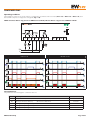
Compressor safety timings
Compressor on-off operations must respect the safety times that you can set using the special parameters as described below.
The compressor LED will flash to indicate when an activate compressor request has been received but a safety protection exists.
A safety time (compressor On... Off safety time) regulated by the parameter dOF must be respected between a switch-off and
switch-on of the same compressor. This waiting time also occurs at switch-on of the device.
A safety time regulated by the parameter dbi must be respected between one switch-on and the next.
The safety time set in parameter dOn must elapse between a start-up request and actual start-up.
Times set with parameters dOn, dOF and dbi, if active, are not accumulative but parallel.
The following diagram illustrates the operation of the compressor protection with parameters dOn, dOF, dbi set where:
IN
OUT
Input state for compressor regulator.
Output state for compressor regulator.
IN
ON
OFF
OUT
ON
OFF
dOn
dOn
dOF
dOF
dbi
dbi
NOTE: See the section entitled Compressor Function During Defrost for other safety measures and compressor
timings.
EWPlus EO Family
Pag. 23/86
DEFROST/COIL DRAINAGE
Description
Defrost is used to stop ice from forming on the surface of the evaporator.
Defrost (see Defrost Modes) basically heats up the evaporator by means of:
• Electrical heaters
• Hot gas
• Simply stopping the compressor and hence the “cooling” cycle
Coil drainage
On completion of defrost, given that there will be water on the evaporator, it is better not to start "cooling" right away as this would
ruin the effect of the defrost by creating ice immediately.
The drainage interval is regulated via parameter dt.
NOTE: parameter dt is only present on models EWPlus 971/974 EO that can control the Evaporator fans
Defrost conditions and function
Defrosting is enabled if:
• the temperature of the evaporator, read by probe Pb2, is less than the defrost end setpoint set in parameter dSt (EWPlus
971/974 EO only with Pb2 probe present - H42 ≠ 0)
• manual defrosting has not already been activated, in which case the request for automatic defrost will be cancelled.
Defrost requests can be made in the following ways:
Controller power-on
Time interval
If parameter dPO (defrost at power-on) is programmed accordingly.
If dit > 0 whenever the defrost time interval set in parameter dit elapses.
Manually via a key
key if enabled (H31 = 1)
By pressing the
The cycle will not start if OdO≠0, the request will be refused and the display will flash three
times to indicate that defrost is impossible.
External request via D.I.
If D.I. appropriately configured.
Activation from D.I. respects the protections of the automatic cycle.
The cycle will not start if OdO≠0, the request will be refused and the display will flash three
times to indicate that defrost is impossible.
User parameters
The parameters that manage this regulator are:
Label
Description
EWPlus EO Model
dty
Selects defrost type
dit
Time interval between 2 consecutive defrost cycles
971/974
All
dCt
Selects the count mode for the defrost interval
All
dOH
Delay in activating defrost cycle after request
All
dEt
Defrost timeout. Determines the maximum defrost duration
All
dSt
Defrost end temperature determined by probe Pb2
dPO
Determines whether the instrument must enter defrost mode at power-on
971/974
All
Fdt
Delay in activating fans after a defrost cycle
971/974
dt
Coil drainage time
971/974
dFd
Allows exclusion of the evaporator fans to be selected or not selected during
defrosting.
971/974
dAO
Temperature alarm disabling time after defrost cycle
dAt
Alarm signalling end of defrost due to timeout
All
971/974
ddL
Display mode during defrost cycle (lock display).
All
dSE
Temperature threshold for start of defrost
All
dtt
Time for which the temperature of the evaporator must remain below dSE
All
Ldd
Timeout value for display unlock - label dEF
All
EWPlus EO Family
Pag. 24/86
Automatic defrost
The defrost cycle is programmed to start at intervals.
NOTE: To disable the automatic cycle, set dit=0.
If dit>0, then defrost cycles will be run at fixed intervals, as indicated in parameter dit, and the interval time is counted as follows:
Parameter
Value
0
(dF)
1
(rt)
dCt
2
(SC)
3
(te)
UM
Description
Compressor
running
Flag time
(DIGIFROST®
method)
Flag
Controller
running time
Notes
In this case, the counter runs only if the compressor is on.
A new count starts when the defrost interval elapses and a new defrost cycle
starts if conditions permit.
NOTE: compressor running time is counted separately from the internal
exchanger temperature.
If the internal exchanger probe is missing or faulty, the count continues
for the time the compressor is on.
The defrost time interval is counted continuously when the controller is on and
starts at each power-on.
A defrost cycle starts when the defrost interval elapses (indicated by dit) if
conditions permit and the controller immediately starts counting a new defrost
interval.
Each time the compressor stops, a defrost cycle is run according to the mode
set in parameter dty.
Flag Compressor stop NOTE: Parameter dty can be viewed and set in models EWPlus 971/974 EO.
In EWPlus 961 models a defrost cycle is performed every time the
compressor stops.
Flag Temperature
Defrost is activated when the evaporator temperature remains below the
threshold dSE for the time dtt.
The time count only starts when defrost is not active.
If probe Pb2 is faulty, defrost is activated based on the interval dit.
IMPORTANT: Regardless of how the interval is counted, the following conditions apply:
EWPlus 961 EO:
•if the parameter OdO timing is in progress, defrost will not be permitted: a new interval will be counted and only at the
end of this subsequent count will conditions for starting a defrost cycle be retested.
EWPlus 971/974 EO:
•if the parameter OdO timing is in progress or the temperature read by the evaporator probe (Pb2) is higher than dSt, then
defrost will not be permitted: a new interval will be counted and only at the end of this subsequent count will conditions
for starting a defrost cycle be retested.
Manual defrost
The device enters defrost mode when the manual defrost key is pressed
(or from Digital Input if H11 or H12 = 1 configured
accordingly). Procedures for the activation of this defrost cycle are the same as for external defrost.
The defrost interval will now be counted as described for Automatic Defrost (time dEt is not cleared, it continues).
If the following conditions are NOT present:
- time set with parameter OdO has not elapsed
- evaporator temperature greater than the value set in parameter dSt (EWPlus 971/974 EO only)
this will be signalled on the display (screen flashes three times) and defrost will stop.
Manual defrost is always enabled except when dit = 0.
EWPlus EO Family
Pag. 25/86
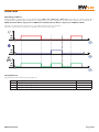
External defrost
If the Digital Input is configured for this function (if H11 or H12 = 1) and if conditions permit, defrost can be requested and the
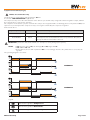
relative regulator activated.
Time graphs for signals in each of the various function modes are presented below.
IMPORTANT: Defrost activation occurs on the leading edge (toggle) of the signal and the polarity is configurable.
Hence you can only activate a defrost, NOT stop one that is underway.
Defrost or coil drainage currently underway and the defrost or coil drainage interval count cannot be
suspended.
IN (Digital Input)
Input state for defrost regulator, with activation from Digital Input.
OUT (Defrost)
Output state for defrost regulator.
DurDI
Digital Input duration.
NOTE
EWPlus 971/974 EO: dSt indicates end defrost time when setpoint temperature reached and dEt
the end of defrost due to timeout.
EWPlus 961 EO:
parameter dSt is not visible, defrost always ends due to timeout (dEt)
The control diagram is as follows:
IN
ON
OFF
OUT
Dur.DI
ON
OFF
(dSt)
dEt
IN
ON
OFF
Dt
OUT
Dt
ON
OFF
(dSt)
(dSt)
dEt
dEt
IN
ON
OFF
Dt
OUT
ON
OFF
(dSt)
(dSt)
dEt
dEt
dit
EWPlus EO Family
Pag. 26/86
Defrost modes
Defrost can be activated in the four ways described below, as set in parameter dtY.
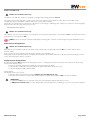
1) Defrost with electrical heaters
EWPlus 971/974 EO models only.
Defrost with electrical heaters is configured by setting dtY = 0 EL.
It is used in "LOW TEMPERATURE" applications.
The compressor stops for the duration of the defrost cycle and the relay configured as defrost regulator output, and that the
electrical heaters are connected to, activates. On completion of defrost, the electrical heaters are switched off and the compressor
remains off for the coil drainage time set in parameter dt, if it is not equal to zero.
Defrost ends due to:
Evaporator probe (Pb2)
Value of H42 End of defrost description
Pb2 ABSENT
H42=0
Due to timeout set in parameter dEt (defrost timeout)
Pb2 PRESENT
H42=1
Temperature setpoint for the end of defrost set in parameter dSt reached.
If this setpoint is not reached within the time set in parameter dEt (defrost
timeout), the defrost will end due to timeout.
NOTES:
• If dSt intervenes before dEt, coil drainage (dt and Fdt) aligns with dSt.
• If Fdt < dt then Fdt = dt.
• During defrost, fans are OFF if parameter dFd is set accordingly, otherwise they will behave as set for the fan regulator.
The operating diagram is as follows:
ON
OFF
ON
OFF
(dS1)
dE1
dt
ON
OFF
Fdt
Legend:
Output state for compressor regulator
Output state for defrost regulator
Output state for evaporator fans regulator
EWPlus EO Family
Pag. 27/86
2) Defrost with compressor stopped
The defrost cycle with the compressor stopped is configured by setting parameter dtY =0 EL.
It is used in "NORMAL TEMPERATURE" applications.
The compressor stops for the duration of the defrost and there is no defrost relay.
Defrost ends due to:
Evaporator probe (Pb2)
Value of H42 End of defrost description
Pb2 ABSENT
H42=0
Due to timeout set in parameter dEt (defrost timeout)
Pb2 PRESENT
H42=1
Temperature setpoint for the end of defrost set in parameter dSt reached.
If this setpoint is not reached within the time set in parameter dEt (defrost
timeout), the defrost will end due to timeout.
IMPORTANT: on model EWPlus 961 EO parameter dt is not visible and cannot be set.
EWPlus 971/974 EO models:on completion of defrost, the compressor relay stays de-energised during the coil
drainage time set in dt (if it is not equal to zero).
The operating diagram is as follows:
ON
OFF
ON
OFF
dEt
dt
ON
OFF
Legend:
Stato Uscita regolatore Compressore
Stato Uscita regolatore Sbrinamento
Stato Uscita regolatore Ventole Evaporatore
EWPlus EO Family
Pag. 28/86
3) Cycle inversion defrost (hot gas)
EWPlus 971/974 models only.
Hot gas defrost is configured by setting parameter dtY = 1.
It is used in "LOW TEMPERATURE" applications.
The compressor stays on for the entire duration of the defrost cycle and the relay configured as defrost regulator output, and that
the solenoid valve is connected to, activates.
On completion of the defrost cycle, the solenoid valve relay is de-energised and the coil drainage phase set in parameter dt (if not
equal to zero) is interrupted. The compressor relay is once again controlled by the compressor regulator.
Defrost ends due to:
Evaporator probe (Pb2)
Value of H42 End of defrost description
Pb2 ABSENT
H42=0
Due to timeout set in parameter dEt (defrost timeout)
Pb2 PRESENT
H42=1
Temperature setpoint for the end of defrost set in parameter dSt reached.
If this setpoint is not reached within the time set in parameter dEt (defrost
timeout), the defrost will end due to timeout.
IMPORTANT: parameters dOn, dOF and dbi (see "Compressor safety timings") have priority.
NOTES:
• If dSt intervenes before dEt, coil drainage (dt and Fdt) aligns with dSt.
• If Fdt < dt then Fdt = dt.
• During defrost, fans are OFF if parameter dFd is set accordingly, otherwise they will behave as set for the fan
regulator.
The operating diagram is as follows:
ON
OFF
ON
DIAGRAM 1
OFF
(dSt)
dEt
dt
ON
OFF
Fdt
ON
OFF
ON
DIAGRAM 2
OFF
(dSt)
dEt
dt
ON
OFF
Fdt
Legend:
Stato Uscita regolatore Compressore
Stato Uscita regolatore Sbrinamento
Stato Uscita regolatore Ventole Evaporatore
EWPlus EO Family
Pag. 29/86
4) Defrost in FREE mode
EWPlus 971/974 EO models only.
The defrost cycle with the compressor stopped is configured by setting parameter dtY =2.
The compressor remains under the control of the compressor regulator for the duration of the defrost cycle and the relay
configured as defrost, and that the defrost heaters are connected to, activates.
The heaters are switched off on completion of the defrost cycle. During coil drainage, the compressor continues to thermoregulate.
Defrost ends in the same way as the previous case.
End of defrost due to timeout
EWPlus 971/974 EO models only.
If the defrost cycle does not terminate on reaching the end of defrost temperature set in parameter dSt, a maximum defrost time
interval can be set in parameter dEt.
NOTE: Defrost can only be terminated manually by switching the controller on and off again using the ON/OFF function.
Alarm function during defrost
EWPlus 971/974 EO models only.
If the defrost cycle ends due to timeout, an alarm can be activated by configuring parameter dAt (see 'end of defrost due to
timeout' alarm).
In the event of an environmental probe (Pb1) error, defrost cycles will still be run.
During defrost, the temperature values recorded by the Evaporator probe (Pb2) and probe 3 (Pb3) may be false readings. For this
reason, the temperature alarm is excluded.
Display function during defrost
By setting parameter ddL (Display mode during defrost cycle - lock display), when the instrument enters defrost mode, the value
shown on the display can be:
• left free to show the temperature read by the environmental probe (Pb1).
• locked at value read by the environmental probe (Pb1) at the start of the defrost cycle.
• locked to display the “dEF” (defrost) label.
Unlock display
The display can be set to unlock:
• when the defrost temperature is reached (EWPlus 971/974 EO models only)
• when the timeout value for unlocking the display elapses, as defined in parameter Ldd (Lock defrost disable).
IMPORTANT:
1) parameter Ldd can be used in a link network to unlock both the display and other resources.
2) EWPlus 971/974 EO only: if set, the display will be unlocked after the coil drainage cycle since it locks the regulators.
EWPlus EO Family
Pag. 30/86
FANS
!
The following section ONLY applies to models EWPlus 971/974 EO since these are the only models with
fan-related parameters.
Operating conditions
The regulator is activated provided that:
• The time set in parameter OdO has elapsed
• the temperature value read by the evaporator probe (Pb2), if present, is less than the value of parameter FSt
• during defrost it has not been excluded by parameter dFd (dFd = y)
• coil drainage is not active (dt)
• fans delay after defrost is not active (Fdt)
The request to switch fans on or off can be made in the following ways:
• by the compressor regulator to help in the “cooling” process (temperature control mode)
• by the defrost regulator to check and/or limit the diffusion of hot air
Day
H42
Probe Pb2 present
Probe Pb2
in error "E2"
Probe Pb2 absent
y
y
n
Night (Energy Saving)
FCO
Compressor ON
Compressor OFF
Compressor ON
Compressor OFF
0
THERMOSTAT CONTROLLED
OFF
THERMOSTAT CONTROLLED
OFF
1
THERMOSTAT CONTROLLED
ON
THERMOSTAT CONTROLLED THERMOSTAT CONTROLLED
2
THERMOSTAT CONTROLLED DUTY CYCLE DAY
THERMOSTAT CONTROLLED
DUTY CYCLE NIGHT
3
DUTY CYCLE DAY
DUTY CYCLE DAY
DUTY CYCLE NIGHT
DUTY CYCLE NIGHT
0
DUTY CYCLE DAY
OFF
DUTY CYCLE NIGHT
OFF
1
DUTY CYCLE DAY
DUTY CYCLE DAY
DUTY CYCLE NIGHT
DUTY CYCLE NIGHT
2
DUTY CYCLE DAY
DUTY CYCLE DAY
DUTY CYCLE NIGHT
DUTY CYCLE NIGHT
3
DUTY CYCLE DAY
DUTY CYCLE DAY
DUTY CYCLE NIGHT
DUTY CYCLE NIGHT
0
ON
OFF
ON
OFF
1
ON
DUTY CYCLE DAY*
ON
DUTY CYCLE NIGHT*
2
ON
DUTY CYCLE DAY*
ON
DUTY CYCLE NIGHT*
3
DUTY CYCLE DAY
DUTY CYCLE DAY
DUTY CYCLE NIGHT
DUTY CYCLE NIGHT
* see paragraph "Fan operation without probe Pb2 (H42 ≠ 0).
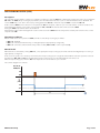
Fan operation in thermostat control
During "cooling", the fans operate as shown in this diagram:
Thermostat control of fans takes place at the values set in parameters
• FSt (fans disabling temperature) and FAd (fans differential).
The fans disabling temperature, set in parameters FSt (fans disabling temperature) and FAd (fans differential), is an absolute value
since FPt = 0 (real temperature value).
Important: when the temperature approaches the start fan temperature (-50°C) the differential will always be referred to
parameter FAd but with the opposite sign.
The fan regulator operates as indicated below:
ON
OFF
FAd
FSt
EWPlus EO Family
°C
(Pb2)
Pag. 31/86
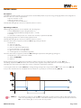
Fan operation in Duty Cycle mode
There are two Duty Cycle modes: Day and Night (Energy Saving).
Activation of Night mode depends on parameter ESF:
ESF = n
Night mode disabled
ESF = y
Night mode active when Energy Saving mode is active
Duty Cycle operation depends on the operating mode, e.g.:
• Day:
parameters Fon and FoF must be set accordingly;
• Night: parameters Fnn and FnF must be set accordingly;
The fans operate as follows:
DUTY CYCLE DAY
Fon
FoF
0
0
OFF
DUTY CYCLE NIGHT
Fan operation
Fnn
FnF
0
0
Fan operation
OFF
0
≠0
OFF
0
≠0
OFF
≠0
0
ON
≠0
0
ON
≠0
≠0
DUTY CYCLE DAY
≠0
≠0
DUTY CYCLE NIGHT
The fan regulator will operate in Duty Cycle mode as shown below:
DUTY-CYCLE DAY
ON
OFF
Fon
FoF
Fon
FoF
DUTY-CYCLE NIGHT
ON
OFF
Fnn
FnF
Fnn
FnF
Fan operation during defrost
During defrost, the fans operate as shown in this diagram
dFd = y : Exclusion of fans during defrost
dFd = n : the fans are not excluded during defrost (see parameters FCO, Fon, FoF,
Fnn and FnF)
OFF
TEMPERATURE CONTROL / DUTY CYCLE
Thermostat control of fans takes place at the values set in parameters:
• FSt (fans disabling temperature) and FAd (fans differential).
NOTE: d
uring defrost with electrical heaters, the compressor is OFF but the fans work as if the compressor was still ON,
unless they have been disabled during defrost (see parameter dFd).
When the evaporator fans are enabled in defrost (dFd = n) and regulate on evaporator probe Pb2 in temperature controlled mode,
if there is an "E2" error in probe Pb2 during defrost, the fans must always be ON, regardless of the values set by the duty cycle.
EWPlus EO Family
Pag. 32/86
Fan operation without probe
If parameter H42 = n (probe Pb2 absent), according to the value of FCO and the state of the compressor, the state of the fans may
be "On", "Off", "Duty Cycle Day" and "Duty Cycle Night".
Parameter FCO will determine the operating mode of the evaporator fans during the "DAY" phase and during the "NIGHT" phase.
FCO = 1
Below is an example of fan operation based on the value set for FCO.
ON
OFF
Fon
ON
FCO = 2
Fon
FoF
OFF
FoF
FoF
Fon
Fon
ON
OFF
Fon
ON
FoF
OFF
FCO = 3
Fon
FoF
FoF
ON
OFF
Fon
ON
Fon
FoF
FoF
Fnn
Fon
FoF
FnF
Fnn
FnF
Fnn
FnF
Fnn
FnF
Fnn
FnF
{
{
OFF
Fon
DAY
EWPlus EO Family
NIGHT
Pag. 33/86
Fan operation during coil drainage
If parameter dt ≠ 0 (coil drainage time), the fans will stay OFF for the time set in this parameter.
See "Defrost with electrical heaters".
Note that if Fdt (fan delay time) is greater than dt (coil drainage time) the fans will stay OFF for the time set in Fdt rather than dt
(e.g. whichever timing is longer will be applied).
Post-ventilation
Parameter FdC delays the switching off of the fans after the compressor has stopped (increasing efficiency of the system by making
better use of inertia). Post-ventilation must be active with any value of FCO and even without the probe configured.
If FdC = 0 the function is disabled.
NOTE: Post-ventilation does not have priority over the delay set in parameter dcd.
User parameters
The parameters that manage the fan regulator are:
Label
FPt
FSt
Fdt
dFd
FCO
FAd
dt
FdC
Fon
FoF
Fnn
FnF
ESF
Description
Characterises parameter “FSt” which can be expressed either as an absolute
temperature value or as a value relative to the Setpoint
Evaporator fans disabling temperature
Evaporator fans delay after defrost cycle
Evaporator fans disabling during defrost time
Evaporator fans operating mode
Evaporator fans activation differential
Coil drainage time
Evaporator fans switch-off delay after compressor disabled
Evaporator fans ON time in duty cycle day mode
Evaporator fans OFF time in duty cycle day mode
Evaporator fans ON time in duty cycle night mode
Evaporator fans OFF time in duty cycle night mode
Night mode activation (Energy saving)
EWPlus EO Family
EWPlus EO Model
971/974
971/974
971/974
971/974
971/974
971/974
971/974
971/974
971/974
971/974
971/974
971/974
971/974
Pag. 34/86
AUXILIARY OUTPUT (AUX/LIGHT)
Description
If relay control is configured as AUX by setting parameter H21 (EWPlus 961/971/974 EO), H22 (EWPlus 971/974 EO) or H23 (EWPlus
974 EO) to the value H2x=5, and by pressing the associated key H32 (DOWN key) or H33 (ESC key), which must be set to the value
H3x=2, the relay activates if it was off and vice versa.
The on/off state is saved in non-volatile memory hence when power returns after a blackout, the device will restart in the state that
was active prior to the blackout.
If parameter H11 or H12 is set to the value H1x=3, the AUX relay is commanded from the digital input; in this case the relay will
reflect the state of the input. In this case, on/off state is not saved in non-volatile memory.
IMPORTANT:the meaning of the D.I. must always remain the same: for example, if the relay is activated by D.I. and
switched off by key, when the D.I. is reset to the starting position, the relay does not change state (since it was
already de-energised via key). With the instrument OFF, if set accordingly, only the digital input (D.I.) and the
associated key can change the state of the output.
Operating conditions
The regulator is activated by:
• Key
• Function
• Digital Input
• Activation of Energy Saving mode
if configured accordingly.
The regulator is not active when:
Condition
during start-up
during standby
(AUX) output state
OFF
state according to parameter H08
NOTES
The values that can be assigned to parameter ESA (AUX/Light output state during Energy Saving) are:
• 0: disabled (no effect on the state of AUX);
• 1: AUX off (LIGHT OFF);
• 2: AUX on;
NOTE: LIGHT management only occurs by setting ESA = 1.
The control diagram is as follows:
D.I.
ON
OFF
ON
OFF
RL
ON
OFF
User parameters
The parameters that manage the auxiliary (AUX) output regulator are:
Label
ESA
H11
H12
H21
H22
H23
H32
H33
Description
AUX state during energy saving:
0 = disabled (no effect on AUX); 1 = AUX off; 2 = AUX on
Configuration of digital input 1 / Polarity
Configuration of digital input 2 / Polarity
Configuration of digital output 1
Configuration of digital output 2
Configuration of digital output 3
Configuration of DOWN key
ESC key configuration
EWPlus EO Family
EWPlus EO Model
All
All
All
All
971/974
974
All
All
Pag. 35/86
PRESSURE SWITCH
Description
This regulator performs diagnostic operations over a digital input activated by setting parameters:
• H11 (D.I.1) = ±7 • H12 (D.I.2) = ±7
If a pressure switch input is activated, power to the compressor is immediately cut off, the relative alarm LED lights up to provide a
visual warning and the folder nPA in the alarms folder AL is also displayed. The folder contains the label with the number of pressure
switch activations (up to the maximum value set in parameter PEn).
When the pressure switch is deactivated because the pressure returns to normal levels, the time set in parameter PEt must elapse
before regulation of cooling mode resumes.
If the number of activations exceeds the maximum number defined by parameter PEn within a time less than the value of PEI, the
following conditions occur:
• The compressor, fans and defrost are disabled
• In the alarms folder AL the label PA (pressure alarm) is displayed in place of folder nPA
• PAL label shown on display
• The alarm relay comes on (if configured).
IMPORTANT: 1) If the number of activations exceeds the number set in PEn within the time limit PEI, the alarm is
automatically reset.
2) The input must be closed on itself if not used and the input is normally closed active, or must be open if
not used and normally open active, or deactivated by digital input configuration parameter.
NOTES: 1) Once the controller is in alarm state, it must be powered off then on, or RESET by activating function rPA
in the functions folder FPr.
2) If parameter PEn = 0, the function is disabled and alarms and counters are also disabled.
3) The pressure switch alarm is not stored in EEPROM.
4) During the pressure switch activation period the defrost interval count runs as normal.
Operating conditions
The number of pressure switch errors is counted using a FIFO method. The time interval PEI is divided into 32 parts; the counter is
incremented by one unit if there are one or more activations during one part of the entire interval PEI.
Two operating examples are given below: In both cases, suppose that PEI = 32 minutes (equal to 32 minutes/32 = 1 minute) and
PEn = 7.
Example 1: ALARM SIGNALLED.The interval for storing activations is 1 minute: all activations within that minute are
counted as a single activation and the alarm (if any) is activated when the sampling interval
has elapsed. In this example the pressure switch alarm is signalled because there have
been 7 activations during the 32 minute time window.
Example 2: ALARM NOT SIGNALLED.
In this example the alarm is not activated because during the 32 minute time window
the number of activations set in parameter PEn was not reached. The time window is a
rolling window and all activations that are outside of it are deleted: the reference point
is the last activation and the time PEI is subtracted from that point to establish how
many activations are included in the count.
Case 1
1
0
1’
3
2
2’
2’
4
1’
6
5
1’
30’’
7
4’
30’’
The time between the 1st and the 7th intervention is 11’ < PEI (32’)
ALARM SIGNAL
Case 2
1
0
1’
3
2
2’
2’
4
1’
6
5
1’
30’’
30’’
The time between the 1st and the 7th intervention is 33’ > PEI (32’)
7
26’
NO ALARM SIGNAL
User parameters
The parameters that manage the pressure switch regulator are:
Label
PEn
PEI
PEt
Description
Number of errors allowed per maximum/minimum pressure switch input
Minimum/maximum pressure switch error count interval (in 32 parts)
Delay in activating compressor after pressure switch deactivation
EWPlus EO Family
EWPlus EO Model
All
All
All
Pag. 36/86
DEEP COOLING CYCLE (DCC)
Description
This regulator means that the compressor regulates in relation to setpoint dCS with a differential equal to the value set in parameter
diF. When the DCC (Deep Cooling Cycle) activates, the interval between defrost cycles is cleared and defrosts are disabled. The
end of a DCC may occur due to timeout, by setting parameter tdc≠0, or when the setpoint dCS is reached if tdc = 0.
At the end of a DCC and once the time set in parameter dcc has elapsed, a defrost cycle is forced and the counters restart for the
interval between defrost cycles (value set in parameter dit). If dcc=0 the defrost starts at the end of the DCC.
During the DCC temperature alarms are disabled.
Normal temperature alarm management resumes at the end of the DCC when the temperature read by Pb1 returns to the control
setpoint value SEt.
Operating conditions
Based on the value set for parameter dCA, activation of the Deep Cooling Cycle will be:
• dCA = 0: disabled;
• dCA = 1: manual (activated via key or via digital input, if appropriately configured);
• dCA = 2: automatic (activated if the temperature read by Pb1 > Sid for a time equal to toS);
Manual mode
Manual mode is activated by setting dCA = 1, consequently the Deep Cooling Cycle will be activated via digital input or via key, if
appropriately configured.
In the event of a probe error and/or power failure, the Deep Cooling Cycle is stopped and standard controller operation restored.
If parameters dCS, tdc and dcc are modified, the Deep Cooling Cycle is recalculated with the new values set.
After a Deep Cooling cycle, the time dcc must elapse before a new defrost cycle can start.
The control diagram is as follows:
DI1, DI2, UP
DOWN, ESC
ON
OFF
°C
(Pb1)
SEt
dCS
tdC
EWPlus EO Family
Pag. 37/86
Automatic mode
Automatic mode is activated by setting dCA = 2, consequently the Deep Cooling cycle will activate as soon as the value read by
probe Pb1 ≥ Sid for a time T ≥ toS and ends when the temperature dCS is reached.
In the event of a probe error and/or power failure, the Deep Cooling Cycle is stopped and standard controller operation restored.
The control diagram is as follows:
°C
Sid
SEt
dCS
SEt
dCS
ON
OFF
toS
User parameters
The parameters that control the Deep Cooling cycle are:
Label
dCA
Description
Enable deep cooling (0 = disabled; 1 = manual; 2 = automatic).
EWPlus EO Model
All
dCS
Deep cooling setpoint
All
tdc
Deep cooling duration
All
dcc
Defrost delay after a Deep Cooling Cycle
All
Sid
Threshold for start of deep cooling
All
toS
Deep cooling activation time
All
EWPlus EO Family
Pag. 38/86
ENERGY SAVING
Description
The EWPlus EO family stands out for its performance and flexibility thanks to special energy saving algorithms and configurations
tailored to the most common applications:
• Open front bottle coolers
• Glass door bottle coolers
• Vertical glass door merchandisers.
The ECO LED will light up in all cases in which the function is active.
Operating conditions
The Energy Saving function can be enabled in the following ways:
• via the DOWN/ESC key (by setting H32/H33 = 6)
• via Digital Input DI1/DI2 (by setting H11/H12 = 9 or 10)
• remotely
• in automatic mode by means of a "virtual" door switch (see parameter (ESP≠0)
The operating algorithms are determined by parameter ESt.
The ECO LED will light up in all cases in which the function is active.
The values that can be assigned to parameter ESt (Energy Saving mode) are:
• 0: disabled;
• 1: offset on setpoint;
• 2: offset on differential;
• 3: offset on setpoint and differential;
• 4: open front bottle cooler algorithm;
• 5: glass door bottle cooler algorithm;
• 6: vertical glass door merchandiser algorithm;
The values that can be assigned to parameter ESA (AUX/Light output state during Energy Saving) are:
• 0: disabled (no effect on the state of AUX);
• 1: AUX off (LIGHT OFF);
• 2: AUX on;
Energy saving can also be enabled via a virtual door switch (only in the case of glass door bottle coolers - ESt = 5).
The setting of parameter ESP determines the sensitivity of the regulator (temperature difference measured by probe 1).
The higher the value (max 5), the higher the system's sensitivity to temperature variations.
1)If using the virtual door switch (ESP ≠ 0) to manage Energy Saving mode only, parameter dOt must be set to zero (dOt = 0).
2) If you also want the fans to be disabled whenever the door is opened, we recommend setting dOt > 0.
ON
OFF
ON
OFF
dOt
NOTE (*):The virtual door switch uses probe Pb1. The algorithm can take several seconds to detect the opening
of the door, depending on the structure of the chiller and the position of the probe. The best location for
Pb1 is on the "intake grill", as close to the door as possible.
EWPlus EO Family
Pag. 39/86
BOTTLE COOLER OPEN FRONT
Whenever the function is enabled, the timers for counting the time dnt and dFt are
reset (zeroed).
Each time that the controller is powered on, the timers for counting the time dnt
and dFt are reset (zeroed) even if they have not elapsed; if however they had
already elapsed, the conditions prior to switch-off are restored.
Activation and deactivation of the "Energy Saving" function only occurs via digital
input (closure of night blind).
If dnt = 0 and dFt = 0 the Energy Saving function is disabled.
The operation of the algorithm is illustrated in the chart below.
The settings are:
• ESt = 4
• H11 = 9
• ESP = 0 (Physical Digital Input - real).
NOTE:
If the night blind is opened during the "Energy Saving" phase, the Fast Cooling
phase starts immediately.
If the night blind is opened during the Fast Cooling phase, the function is
terminated when the time dFt elapses.
°C
ENVIRONMENTALLY OPTIMISED
8°C
6°C
ON
OFF
SPn
SEt
SPF
ON
OFF
dnt
dFt
FAST
COOLING
EWPlus EO Family
Pag. 40/86
BOTTLE COOLER GLASS DOOR
If the door remains closed for a time greater than parameter cdt and the SEt has
been reached during this period, Energy Saving mode will be activated. It will be
disabled when the time set in parameter dnt elapses or when the door is opened.
The requirement for the temperature to have reached the value of SEt is due to the
fact that, if the cooling system is not working correctly (e.g.: refrigerant gas low) or
the temperature of the room is too high and the system cannot reach the optimal
temperature during the day, and if Energy Saving mode is activated, when it ends
the system would not be able to bring the temperature of the bottles back down to
the set value.
At the end of the Energy Saving period, a mode called "Quick Chill" starts. This fully
automatic mode brings the temperature of the bottles back down to the desired
value in the shortest possible time (the algorithm is able to recognise and adapt to
the characteristics of the application).
If dnt = 0 Quick Chill and Energy Saving mode are disabled.
The way in which the algorithm works is illustrated in the chart below.
The settings are:
• ESt = 5
• H11/H12 = 10 and ESP = 0 (in case of physical Digital Input)
• ESP≠0 and H11/H12 ≠ 2,4,9 and 10 (in case of virtual Digital Input)
NOTE:
1) If ESt = 5, after a power cut, the device will function continuously in standard (day)
mode until the door is closed. If the door is not opened/closed, then after a time Cdt
the device will function continuously in Economy (Energy Saving) mode for a period
equal to: dnt.
2) If the door is opened during the Energy Saving phase, the Quick Chill phase starts
immediately. if the door is opened during the Quick Chill phase, the function will
deactivate as normal.
°C
ENVIRONMENTALLY OPTIMISED
8°C
6°C
ON
OFF
SPn
SEt
ON
OFF
ON
OFF
2
12
QUICK
CHILL
dnt
cdt
24 26
36
48 50
0
(h)
ON
OFF
cdt
EWPlus EO Family
dnt
Pag. 41/86
VERTICAL DISPLAY CABINET WITH DOOR
If the door remains closed for a time greater than the parameter cdt, Energy
Saving mode is activated.
Energy Saving mode is disabled automatically based on the usage
conditions of the chiller (quantity of warm air entering the chiller).
The deactivation "threshold" can be set by means of parameter ESo.
For example:
• ESo = 0 high usage before deactivation of Energy Saving mode
• ESo = 10 low usage before deactivation of Energy Saving mode
This mode is deactivated automatically even when a "Defrost with
heaters" mode is activated.
The operation of the algorithm is illustrated in the chart below.
The settings are:
• ESt = 6
• H11 = 10
• ESP = 0 (Physical Digital Input - real).
°C
ENVIRONMENTALLY OPTIMISED
7°C
6°C
ON
OFF
SPn
SEt
ON
OFF
Fon/FoF
Fon/FoF
Fon/FoF
Fnn/FnF
Fnn/FnF
Fon/FoF
cdt
EWPlus EO Family
Pag. 42/86
User parameters
The parameters that control the Energy Saving cycle are:
Label
Description
EWPlus EO Model
ESt
Energy Saving mode:
0= disabled; 1= Offset on setpoint; 2= Offset on differential;
3= offset on setpoint and differential; 4= "Open front bottle cooler" algorithm;
5= "Glass door bottle cooler" algorithm; 6= "Vertical glass door merchandiser" algorithm
All
ESA
AUX state during energy saving:
0 = disabled (no effect on AUX); 1 = AUX off; 2 = AUX on
All
Cdt
ESo
OSP
OdF
dnt
dFt
SPn
dFn
SPF
dFF
Sid
ESP
dOt
Door close time
Cumulative door open time for disabling Energy Saving mode
Setpoint offset
Differential offset
Night mode duration
Fast cooling duration
Night mode setpoint
Night mode differential
Fast cooling setpoint
Fast cooling differential
Threshold for start of deep cooling
Sensitivity of virtual door regulator
Maximum door open time with virtual door switch
All
All
All
All
All
All
All
All
All
All
All
All
All
COOL PROTECTION
Description
When the temperature measured by probe 1 falls below the temperature set in parameter cPS for the time cPt, antifreeze
protection mode is activated to heat the cabinet by activating the light and the fans, until the temperature (cPS + differential cPd) is
reached. If cPt = 0 the function is disabled.
Control diagram
Pb1
CPd
CPS
CPt
ON
OFF
ON
OFF
User parameters
The parameters that manage the auxiliary (AUX) output regulator are:
Label
cPS
cPd
CPt
Description
Enable utility switch-off on activation of digital input
(set as door switch)
Digital input activation delay
Compressor switch off delay from door switch
EWPlus EO Family
EWPlus EO Model
All
All
All
Pag. 43/86
CONDENSER FANS
Operating conditions
The regulator is active if one of the relays is configured as "Condenser fans reversal" (H21 = ±8 or H22 = ±8 or H23 = ±8) and
defrost with compressor stopped is configured. (dty = +0).
NOTE: Parameter H22 is only present on EWPlus 971/974 EO, whereas H23 is only present on EWPlus 974 EO
EWPLUS 974
TTL
(C)
(A)
(B)
A
Alimentazione
230Va - 4.5W
8 9 10 11
1 2 3 4 5 6 7
N
L
DAY mode
NIGHT mode
ON
ON
OFF
OFF
ON
ON
OFF
OFF
ON
ON
OFF
OFF
ON
ON
OFF
OFF
ON
ON
OFF
OFF
dFA
dFA
dFA
dFA
dFA
dFA
dFA
dFA
dFA
dFA
User parameters
The parameters that manage the condenser fans are:
Label
Description
EWPlus EO Model
dFA
Compressor and condenser fans activation delay after command
dty
Type of defrost.
1 = Cycle inversion defrost;
H21
Configurability of digital output 1.
All
H22
Configurability of digital output 2.
971/974
H23
Configurability of digital output 3.
974
EWPlus EO Family
0 = Electric defrost;
2 = Free mode defrost
All
971/974
Pag. 44/86
CHECK VALVE
Operating conditions
By appropriately configuring one of the digital outputs (H21 = ±9 or H22 = ±9 or H23 = ±9) it is possible to control a check valve
to prevent the "migration" and resulting loss of refrigerant gas from the refrigeration circuit when the compressor is switched off.
NOTE: Parameter H22 is only present on EWPlus 971/974 EO, whereas H23 is only present on EWPlus 974 EO
The valve is active when the compressor is on or when a defrost cycle is in progress.
The valve is off when the compressor is off and no defrost cycles are active.
ON
OFF
ON
OFF
R
ON
OFF
User parameters
The parameters that control the check valve are:
Label
Description
EWPlus EO Model
H21
Configurability of digital output 1.
All
H22
Configurability of digital output 2.
971/974
H23
Configurability of digital output 3.
974
EWPlus EO Family
Pag. 45/86
DOOR SWITCH INPUT
Operating conditions
The door switch input is associated to an appropriately configured digital input (H11 = ±4 or H12 = ±4).
By controlling the opening of the door, it is possible to deactivate the compressor output and/or the fans.
It is also possible to associate a deactivation delay to the compressor output by means of parameter dCO.
If the door is opened during a defrost cycle, the cycle is not shut down.
When the door is opened, the controller operates as follows based on the value of parameters dOd and dCO:
dOd
dOd = 0
dOd = 1
dOd = 2
dOd = 3
Fans (FAN)
ON
OFF
ON
OFF
Compressor (COMP)
ON
ON
OFF after time dCO
OFF after time dCO
User parameters
The parameters that manage the auxiliary (AUX) output regulator are:
Label
dAd
Description
Enable utility switch-off on activation of digital input
(set as door switch)
Digital input activation delay
OAO
Alarms signalling delay after disabling of digital input
(door closing)
All
tdO
Door open alarm delay time
All
dCO
Compressor switch off delay from door switch
All
dOd
EWPlus EO Model
All
All
STANDBY
Operating conditions
The Standby regulator can be activated by digital input (if configured) or by key (if programmed).
With the device OFF the display shows "OFF" and all regulators are blocked including alarms.
When the device is switched on via a key or an appropriately configured digital input, regular operation commences, the same as
from power-on. After power-on, the temperature alarm is excluded for a time set in parameter PAO, and the delay set in parameter
OdO is activated.
Each time that the device is switched off, all cycle times are reset.
The on/off state is saved in non-volatile memory hence when power returns after a blackout, the device will restart in the state that
was active prior to the blackout.
The output from standby is linked to the delay set in parameter OdO.
NOTE: When the controller is switched off, all relays are de-energised except for Aux: button/aux input-light-door switch are active.
User parameters
The parameters that manage the Standby regulator are:
Label
Description
PAO
Alarm disabling after power-on
EWPlus EO Model
All
OdO
Delay output enabling from power-on
All
OAO
High and low temperature alarms disabling time after door closing
All
EWPlus EO Family
Pag. 46/86
PARAMETER TABLE
EWPlus 961 TABLES
"USER" MENU PARAMETERS TABLE
SEt Temperature control SEtpoint
LSE ... HSE
Value for Application
1
2
3
4
°C/°F 3,5 3,5 3,5 3,5
diF Compressor relay activation differential
0,1 ... 30,0
°C/°F 2,0
HSE Maximum value settable for setpoint
LSE ... 320
°C/°F 99,0 99,0 99,0 99,0
LSE Minimum value settable for setpoint
-67,0 ... HSE
°C/°F -50,0 -50,0 -50,0 -50,0
Cat Par. Description
Range
M.U.
2,0
2,0
2,0
dit Interval between the start of two consecutive defrost cycles
0 ... 250
hours
24
24
24
24
dEt Defrost timeout.
1 ... 250
min
30
30
30
30
HAL Maximum temperature alarm
LAL ... 320
°C/°F 50,0 50,0 50,0 50,0
LAL Minimum temperature alarm
-67,0 ... HAL
°C/°F -50,0 -50,0 -50,0 -50,0
tAO Time delay for temperature alarm indication
0 ... 250
dCS Deep cooling cycle setpoint
-67,0 ... 320
tdC Deep cooling cycle duration
0 ... 255
OSP Offset on setpoint
OdF Activation differential correction
min
0
min
0
-30,0 ... 30,0 °C/°F 0,5
0,0 ... 30,0
0
0
0
°C/°F -2,0 -2,0 -2,0 -2,0
0
0
0
0,5
1,0
1,0
°C/°F 4,0
4,0
2,0
2,0
dnt Night mode duration
0 ... 24
hours
11
11
10
9
dFt Fast cooling duration
0 ... 24
hours
0
0
1
1
SPn Night mode setpoint
LSE ... HSE
°C/°F 0,7
0,7
3,0
6,5
dFn Night mode differential
0,1 ... 30,0
°C/°F 4,0
4,0
2,0
0,1
SPF Fast cooling setpoint
LSE ... HSE
°C/°F 0,0
0,0
-0,5 -6,8
dFF Fast cooling differential
0,1 ... 30,0
°C/°F 0,1
0,1
0,1
0,1
LOC Basic commands edit lock
PA1 PS1 PAssword1: if PS1≠0 it is the password to the “User” parameters
n/y
flag
n
n
n
n
0 ... 250
num
0
0
0
0
Pb1 CA1 Calibration 1. Temperature value to be added to the value of Pb1
-12,0 ... +12,0 °C/°F 0,0
0,0
0,0
0,0
Pb3 CA3 Calibration 3. Temperature value to be added to the value of Pb3
Display mode during defrost.
0 = display the temperature read by probe Pb1;
1 = locks the reading at the temperature value read by Pb1 when
ddL
defrosting starts and until the next time the SEt value is reached;
2 = displays the label deF during defrosting and until the next time the
SEt value is reached (or until Ldd has elapsed).
Ldd Timeout value for display unlock - label dEF
-12,0 ... +12,0 °C/°F 0,0
0,0
0,0
0,0
-
0/1/2
num
1
1
1
1
0 ... 255
min
30
30
30
30
reL Device version. Read-only parameter
/
/
/
/
/
/
tAb Parameters tAble. Reserved: read-only parameter
/
/
/
/
/
/
PA2 Folder that permits access to the “Installer” menu. If PS2≠0 the password will be requested.
NOTES: * The “USER” menu parameters also include PA2 which permits access to the “Installer” menu
** For the complete list of parameters, see the “Installer Menu Parameters Table”.
EWPlus EO Family
Pag. 47/86
"INSTALLER" MENU PARAMETERS TABLE
Cat Par. Description
Control SEtpoint with range between the minimum Setpoint LSE and the
SEt maximum Setpoint HSE. The setpoint value is located in the Machine Status
menu.
Range
M.U.
Value for Application
1
2
3
4
LSE...HSE
°C/°F 3,5
3,5
3,5
3,5
diFferential. Compressor relay activation differential; the compressor stops
on reaching the setpoint value (as indicated by the regulation probe) and
diF
restarts at a temperature value equal to the setpoint plus the value of the
differential. Note: cannot be equal to 0.
0,1...30,0
°C/°F 2,0
2,0
2,0
2,0
HSE Higher SEt. Maximum value settable for setpoint
LSE...320
°C/°F 99,0 99,0 99,0 99,0
COMPRESSOR (folder "CP")
LSE Lower SEt. Minimum value settable for setpoint
Controller switch-on time in the event of faulty probe:
Ont - if Ont = 1 and OFt = 0, the compressor will always stay ON;
- if Ont = 1 and OFt > 0, it operates in Duty Cycle mode.
Controller switch-off time in the event of a faulty probe:
OFt - if OFt = 1 and Ont = 0, the controller will always stay OFF;
- if Ont = 1 and OFt > 0, it operates in Duty Cycle mode.
-67,0...HSE °C/°F -50,0 -50,0 -50,0 -50,0
0 ... 250
min
0
0
0
0
0 ... 250
min
1
1
1
1
0 ... 250
secs
0
0
0
0
0 ... 250
min
0
0
0
0
0 ... 250
min
0
0
0
0
OdO Delay in activating outputs after the instrument is switched on or after a
(!) power failure. 0 = not active
0 ... 250
min
0
0
0
0
dFA Compressor and condenser fans activation delay after command
0 ... 255
secs
0
0
0
0
0 ... 250
hours
24
24
24
24
0/1/2/3
num
1
1
1
1
defrost Offset Hour.
Delay for start of first defrost after request.
0 ... 59
min
0
0
0
0
defrost Endurance time.
Defrost timeout; determines the maximum defrost duration.
1 ... 250
min
30
30
30
30
n/y
flag
n
n
n
n
0,0
0,0
0,0
dOn
delay (at) On compressor.
Compressor relay activation delay after request.
delay (after power) OFF.
dOF Delay time after power-off: the delay time indicated must elapse between
deactivation of the compressor relay and the next power-on.
Delay between power-ons.
dbi Delay time between power-ons; the delay time indicated must elapse
between two consecutive compressor power-ons.
DEFROST (folder "dEF")
defrost interval time.
dit
Interval between the start of two consecutive defrost cycles.
Selects the count mode for the defrost interval:
0 = compressor running time (DIGIFROST® method);
Defrost active ONLY when the compressor is on.
NOTE: compressor running time is counted separately from the
evaporator probe (count active also when evaporator probe missing or
dCt faulty).
1 = appliance running time; defrost counting is always active when the
machine is on and starts at each power-on.
2 = compressor stop. Every time the compressor stops, a defrost cycle is
performed according to parameter dtY;
3 = not USED
dOH
dEt
defrost (at) Power On.
dPO Determines whether the instrument must enter defrost mode (if the
temperature measured by Pb2 allows this operation). n = no; y = yes.
dSE Temperature threshold for start of defrost.
dtt Time for which the temperature of the evaporator must remain below dSE
ALARMS (folder "AL")
Can be used to select absolute (Att=0) or relative (Att=1) values for HAL
and LAL parameters.
Att NOTE: In case of relative values (para. Att=1), the HAL parameter
should be set to positive values, while the LAL parameter should be
set to negative values (-LAL).
EWPlus EO Family
-67,0...320 °C/°F 0,0
0 ... 255
min
0
0
0
0
0/1
num
1
1
1
1
Pag. 48/86
Cat Par. Description
AFd Alarms activation differential.
Maximum temperature alarm. Temperature value (intended either as
distance from setpoint or as an absolute value based on Att) which, if
HAL
exceeded in an upward direction, triggers the activation of the alarm signal.
See “Max/Min temperature alarms”.
Minimum temperature alarm. Temperature value (intended as distance
from the set point or as an absolute value based on Att) which, when
LAL
exceeded downwards, triggers the activation of the alarm signal.
See “Max/Min temperature alarms”.
PAO
Alarm override time after device is switched on following a power failure.
This parameter refers to high/low temperature alarms only.
dAO Temperature alarm exclusion time after defrost.
OAO
Alarm signal delay (low and high temperature) after the deactivation of the
digital input (port closed).
tdO Delay in door open alarm activation.
Time delay for temperature alarm indication.
tAO
This parameter refers to high/low temperature alarms only.
rLO An external alarm locks the regulators. n = does not lock; y = locks
Range
M.U.
Value for Application
1
1,0 ... 50,0 °C/°F 2,0
LAL...320
2
2,0
3
2,0
4
2,0
°C/°F 50,0 50,0 50,0 50,0
-67,0...HAL °C/°F -50,0 -50,0 -50,0 -50,0
0 ... 10
hours
0
0
0
0
0 ... 999
min
0
0
0
0
0 ... 10
hours
0
0
0
0
0 ... 250
min
0
0
0
0
0 ... 250
min
0
0
0
0
n/y
flag
n
n
n
n
SA3 Probe 3 alarm Setpoint.
-67,0...320 °C/°F 30,0 30,0 30,0 30,0
dA3 Probe 3 alarm differential.
1,0 ... 50,0 °C/°F 1,0
1,0
1,0
1,0
COOL PROTECTION (folder "CPr")
CPS Cool protection setpoint
-67,0...320 °C/°F -10,0 -10,0 -10,0 -10,0
CPd Cool protection differential
0,1...30,0
°C/°F 1,0
1,0
1,0
1,0
Cpt Time that the temperature remains below the cool protection setpoint (CPS)
0 ... 255
min
0
0
0
0
LIGHTS & DIGITAL INPUTS (folder "Lit")
Digital input for switching off utilities:
0 = disabled;
dOd 1 = disables the fans;
2 = disables the compressor;
3 = disables fans and compressor.
dAd Activation delay for digital input
0/1/2/3
num
1
1
1
1
0 ... 255
min
0
0
0
0
dCO Compressor enabling delay from acknowledgement
0 ... 255
min
0
0
0
0
dCd Delay in activating fans after door closed
0 ... 250
secs
10
10
10
10
0 ... 15
num
5
5
5
5
PRESSURE SWITCH (folder "PrE")
Pen Number of errors allowed per maximum/minimum pressure switch input
PEI Minimum/maximum pressure switch error count interval
1 ... 99
min
1
1
1
1
PEt Delay in activating compressor after pressure switch deactivation
0 ... 255
min
0
0
0
0
DEEP COOLING (folder "dEC")
Enable deep cooling (0 = disabled; 1 = manual; 2 = automatic).
Deep cooling setpoint
Deep cooling duration
Defrost delay after a Deep Cooling Cycle
Threshold for start of deep cooling
Deep cooling activation time
ENERGY SAVING (folder "EnS")
Energy Saving mode:
0= disabled; 1= Offset on setpoint;
2= Offset on differential; 3= offset on setpoint and differential;
ESt
4= "Open front bottle cooler" algorithm; 5= "Glass door bottle cooler"
algorithm; 6= "Vertical glass door merchandiser" algorithm.
AUX state during energy saving:
ESA
0 = disabled (no effect on AUX); 1 = AUX off; 2 = AUX on
Night mode (energy saving) activation for fans.
ESF n = disabled;
y = enabled if energy saving mode is active (ESt ≠ 0)
dCA
dCS
tdC
dCC
Sid
tOS
Cdt Door close time
EWPlus EO Family
0/1/2
num
2
2
2
2
-67,0...320 °C/°F -2,0 -2,0 -2,0 -2,0
0 ... 255
min
0
0
0
0
0 ... 255
min
0
0
0
0
-67,0...320 °C/°F 12,0 12,0 12,0 12,0
0 ... 255
min
5
5
5
5
0 ... 6
num
5
5
4
4
0/1/2
num
0
0
0
0
n/y
flag
y
y
y
y
0 ... 255
min
(*10)
6
6
6
6
Pag. 49/86
Cat Par. Description
ESo Cumulative door open time for disabling Energy Saving mode
Range
M.U.
0 ... 10
num
Value for Application
1
0
2
3
4
0
0
0
OSP Setpoint offset
-30,0...30,0 °C/°F 0,5
0,5
1,0
1,0
OdF Differential offset
0,0 ... 30,0 °C/°F 4,0
4,0
2,0
2,0
dnt Night mode duration
0 ... 24
hours
11
11
10
9
dFt Fast cooling duration
0 ... 24
hours
0
0
1
1
SPn Night mode setpoint
LSE ... HSE °C/°F 0,7
0,7
3,0
6,5
dFn Night mode differential
0,1 ... 30,0 °C/°F 4,0
4,0
2,0
0,1
SPF Fast cooling setpoint
LSE ... HSE °C/°F 0,0
0,0
-0,5 -6,8
dFF Fast cooling differential
0,1 ... 30,0 °C/°F 0,1
ESP Sensitivity of virtual door regulator
dOt Maximum door open time with virtual door switch
0,1
0,1
0,1
0 ... 5
num
0
0
0
0
0 ... 255
secs
0
0
0
0
COMMUNICATION (folder "Add")
PtS Selection of communication protocol. t = Televis; d = Modbus
t/d
flag
t
t
t
t
dEA Index of the device within the family (valid values from 0 to 14)
0 ... 14
num
0
0
0
0
Device family (valid values from 0 to 14). The pair of values FAA and dEA
FAA are the network address of the device and are given in the format "FF.DD"
(where FF=FAA and DD=dEA).
0 ... 14
num
0
0
0
0
Pty Modbus parity bit. n=none; E=even; o=odd
n/E/o
flag
n
n
n
n
StP Modbus stop bit
1b/2b
flag
1b
1b
1b
1b
n/y
flag
n
n
n
n
0 ... 250
num
0
0
0
0
0 ... 250
num
15
15
15
15
n/y
flag
y
y
y
y
DISPLAY (folder "DiS")
LOCk. Setpoint edit lock. See corresponding paragraph.
You will still be able to open parameter programming and alter
LOC
parameters, including the state of this parameter if you need to unlock the
keyboard for example. y = yes; n = no.
PAssword1.
PA1 PS1
When enabled (PS1≠0) it is the password to the “User” parameters
PA2 PS2
PAssword2.
When enabled (PS2≠0) it is the password to the “Installer” parameters
ndt number display type. Display with decimal point. y = yes; n = no
Pb1 CA1
Calibration 1.
Positive or negative temperature value to be added to the value of Pb1.
-12,0...+12,0 °C/°F 0,0
0,0
0,0
0,0
Pb3 CA3
Calibration 3.
Positive or negative temperature value to be added to the value of Pb3.
-12,0...+12,0 °C/°F 0,0
0,0
0,0
0,0
Display mode during defrost.
0 = display the temperature read by probe Pb1;
1 = locks the reading at the temperature value read by Pb1 when
ddL
defrosting starts and until the next time the SEt value is reached;
2 = displays the label deF during defrosting and until the next time the
SEt value is reached (or until Ldd has elapsed).
Ldd Timeout value for display unlock - label dEF
Select the unit of measurement used when displaying the temperature
recorded by the probes. (0 = °C, 1 = °F).
dro
NOTE: switching between °C and °F DOES NOT modify the SEt, diF
values, etc. (e.g. set=10°C becomes 10°F)
Selects type of value to display.
ddd
0 = Setpoint; 1 = probe Pb1 ; 2 = probe Pb2 ; 3 = probe Pb3
0/1/2
num
1
1
1
1
0 ... 255
min
30
30
30
30
0/1
num
0
0
0
0
0/1/2/3
num
1
1
1
1
0/1/2
num
2
2
2
2
CONFIGURATION (folder "CnF")
Function when in standby mode.
0 = display off; the regulators are active and the device reactivates the
H08
display to signal any alarms.
1 = display off; regulators and alarms blocked.
2 = display shows OFF label; regulators and alarms blocked.
EWPlus EO Family
Pag. 50/86
Cat Par. Description
Configuration of digital input 1/polarity.
0 = disabled; ±1 = defrost;
±2 = reduced set; ±3 = AUX;
±4 = door switch; ±5 = external alarm; ±6 = standby;
D.I.1 H11 ±7 = pressure switch; ±8 = Deep Cooling; ±9 = energy saving;
±10 = door switch + energy saving
Range
M.U.
-10 ... +10
Value for Application
1
2
3
4
num
10
0
9
9
-10 ... +10
num
0
0
0
0
NOTE: • the “+” sign indicates input active if contact is closed.
• the “-” sign indicates input active if contact is open.
D.I.2 H12 Configuration of digital input 2/polarity. Same as H11.
H21
Configurability of digital output 1.
0 = disabled; 1 = compressor; 2 = defrost; 3 = fans;
4 = alarm;
5 = AUX;
6 = Standby; 7 = NOT USED;
8 = condenser fans reversal; 9 = check valve.
0 ... 9
num
1
1
1
1
H25
Enable/disable buzzer.
0 = disabled; 4 = enabled; 1-2-3-5-6-7-8-9 = NOT USED;
0 ... 9
num
0
0
0
0
0 ... 6
num
0
0
0
0
0 ... 6
num
4
4
4
4
Configurability of DOWN key.
DOWN H32 0 = disabled; 1 = defrost; 2 = AUX; 3 = reduced set; 4 = standby;
5 = deep cooling; 6 = energy saving
ESC
H33 ESC key configuration. Same as H32.
Pb3 H43 Probe Pb3 present. n = not present; y = present
n/y
flag
n
y
n
n
-
reL Device version. Read-only parameter
/
/
/
/
/
/
-
tAb Parameters tAble. Reserved: read-only parameter
/
/
/
/
/
/
/
/
/
/
/
/
/
/
/
/
/
/
/
/
/
/
/
/
COPY CARD (folder "FPr")
UL Transfer programming parameters from instrument to Copy Card
Fr
Format Copy Card. Erases all data contained in the Copy Card.
NOTE: If parameter “Fr” is used, the data entered will be permanently
lost. This operation cannot be reversed.
FUNCTIONS (folder "FnC")
rAP Reset pressure switch alarms
NOTE:
1) If one or more parameters marked with (!) in folder "CnF" are modified, the controller MUST be switched off
and then switched on again to ensure correct operation.
EWPlus EO Family
Pag. 51/86
EWPlus 971 TABLES
"USER" MENU PARAMETERS TABLE
SEt Temperature control SEtpoint
LSE ... HSE
Value for Application
1
2
3
4
°C/°F 3,5 1,5 1,0 3,5
diF Compressor relay activation differential
0,1 ... 30,0
°C/°F 2,0
LSE ... 320
°C/°F 99,0 99,0 99,0 99,0
-67,0 ... HSE
°C/°F -50,0 -50,0 -50,0 -50,0
Cat Par. Description
HSE Maximum value settable for setpoint
LSE Minimum value settable for setpoint
Type of defrost.
0 = Electric defrost;
dty
1 = Cycle inversion defrost;
2 = Defrost independent of compressor.
dit Interval between the start of two consecutive defrost cycles
dEt Defrost timeout.
Range
M.U.
4,0
2,0
2,0
0/1/2
num
0
0
1
0
0 ... 250
hours
24
2
6
24
min
30
30
30
30
dSt Defrost end temperature (determined by probe Pb2).
-67,0 ... 320
1 ... 250
°C/°F 8,0
3,0
8,0
8,0
FSt Fans disabling temperature.
-67,0 ... 320
°C/°F 50,0
Fdt Fan activation delay after a defrost cycle.
0 ... 250
min
0
dt Coil drainage time.
Allows exclusion of the evaporator fans to be selected or not selected
dFd
during defrosting.
HAL Maximum temperature alarm
0 ... 250
min
0
n/y
flag
y
LAL Minimum temperature alarm
tAO Time delay for temperature alarm indication
0
0
y
°C/°F 50,0 50,0 50,0 50,0
-67,0 ... HAL
°C/°F -50,0 -50,0 -50,0 -50,0
0 ... 250
-67,0 ... 320
tdC Deep cooling cycle duration
0 ... 255
OdF Activation differential correction
0
0
LAL ... 320
dCS Deep cooling cycle setpoint
OSP Offset on setpoint
50,0
min
0
0
0
°C/°F -2,0 -2,0 -2,0 -2,0
min
0
-30,0 ... 30,0 °C/°F 0,5
0
0
0
1,0
0,5
0,5
°C/°F 4,0
2,0
4,0
4,0
0 ... 24
hours
11
10
10
11
dFt Fast cooling duration
0 ... 24
hours
0
SPn Night mode setpoint
LSE ... HSE
°C/°F 0,7
dFn Night mode differential
0,1 ... 30,0
SPF Fast cooling setpoint
LSE ... HSE
dFF Fast cooling differential
0,1 ... 30,0
dnt Night mode duration
LOC Basic commands edit lock
PA1 PS1 PAssword1: if PS1≠0 it is the password to the “User” parameters
0,0 ... 30,0
0
1
1
0
3,0
1,0
0,7
°C/°F 4,0
2,0
4,0
4,0
°C/°F 0,0
-0,5 -2,0
0,0
°C/°F 0,1
0,1
0,1
0,1
n
n
n
n/y
flag
n
0 ... 250
num
0
0
0
0
Pb1 CA1 Calibration 1. Temperature value to be added to the value of Pb1
-12,0 ... +12,0 °C/°F 0,0
0,0
0,0
0,0
Pb2 CA2 Calibration 2. Temperature value to be added to the value of Pb2
-12,0 ... +12,0 °C/°F 0,0
0,0
0,0
0,0
Pb3 CA3 Calibration 3. Temperature value to be added to the value of Pb3
Display mode during defrost.
0 = display the temperature read by probe Pb1;
1 = locks the reading at the temperature value read by Pb1 when
ddL
defrosting starts and until the next time the SEt value is reached;
2 = displays the label deF during defrosting and until the next time the
SEt value is reached (or until Ldd has elapsed).
Ldd Timeout value for display unlock - label dEF
-12,0 ... +12,0 °C/°F 0,0
0,0
0,0
0,0
Pb2 H42 Evaporator probe (Pb2) present. n = not present; y = present
0/1/2
num
1
1
1
1
0 ... 255
min
30
30
30
30
n/y
flag
y
y
y
y
-
reL Device version. Read-only parameter
/
/
/
/
/
/
-
tAb Parameters tAble. Reserved: read-only parameter
/
/
/
/
/
/
PA2 Folder that permits access to the “Installer” menu. If PS2≠0 the password will be requested.
NOTES: *
**
The “USER” menu parameters also include PA2 which permits access to the “Installer” menu
For the complete list of parameters, see the “Installer Menu Parameters Table”.
EWPlus EO Family
Pag. 52/86
"INSTALLER" MENU PARAMETERS TABLE
Cat Par. Description
Control SEtpoint with range between the minimum Setpoint LSE and the
SEt maximum Setpoint HSE. The setpoint value is located in the Machine Status
menu.
Range
M.U.
Value for Application
1
2
3
4
LSE...HSE
°C/°F 3,5
1,5
1,0
3,5
diFferential. Compressor relay activation differential; the compressor stops
on reaching the setpoint value (as indicated by the regulation probe) and
diF
restarts at a temperature value equal to the setpoint plus the value of the
differential. Note: cannot be equal to 0.
0,1...30,0
°C/°F 2,0
4,0
2,0
2,0
HSE Higher SEt. Maximum value settable for setpoint
LSE...320
°C/°F 99,0 99,0 99,0 99,0
COMPRESSOR (folder "CP")
LSE Lower SEt. Minimum value settable for setpoint
Controller switch-on time in the event of faulty probe:
Ont - if Ont = 1 and OFt = 0, the compressor will always stay ON;
- if Ont = 1 and OFt > 0, it operates in Duty Cycle mode.
Controller switch-off time in the event of a faulty probe:
OFt - if OFt = 1 and Ont = 0, the controller will always stay OFF;
- if Ont = 1 and OFt > 0, it operates in Duty Cycle mode.
-67,0...HSE °C/°F -50,0 -50,0 -50,0 -50,0
0 ... 250
min
0
1
0
0
0 ... 250
min
1
1
1
1
0 ... 250
secs
0
15
0
0
0 ... 250
min
0
3
0
0
0 ... 250
min
0
0
0
0
OdO Delay in activating outputs after the instrument is switched on or after a
(!) power failure. 0 = not active
0 ... 250
min
0
0
0
0
dFA Compressor and condenser fans activation delay after command
0 ... 255
secs
0
0
0
0
0/1/2
num
0
0
1
0
0 ... 250
hours
24
2
6
24
0/1/2/3
num
1
0
1
1
defrost Offset Hour.
Delay for start of first defrost after request.
0 ... 59
min
0
0
0
0
dEt
defrost Endurance time.
Defrost timeout; determines the maximum defrost duration.
1 ... 250
min
30
30
30
30
dSt
defrost Stop temperature.
Defrost end temperature (determined by probe Pb2).
-67,0...320 °C/°F 8,0
3,0
8,0
8,0
n
n
n
dOn
delay (at) On compressor.
Compressor relay activation delay after request.
delay (after power) OFF.
dOF Delay time after power-off: the delay time indicated must elapse between
deactivation of the compressor relay and the next power-on.
Delay between power-ons.
dbi Delay time between power-ons; the delay time indicated must elapse
between two consecutive compressor power-ons.
DEFROST (folder "dEF")
defrost type. Type of defrost.
0 = electric defrost - compressor off (OFF) during defrosting;
dty 1 = cycle inversion defrost (hot gas); compressor on
during defrosting:
2 = Free mode defrost; defrost independent of compressor.
dit
defrost interval time.
Interval between the start of two consecutive defrost cycles.
Selects the count mode for the defrost interval:
0 = compressor running time (DIGIFROST® method);
Defrost active ONLY when the compressor is on.
NOTE: compressor running time is counted separately from the
evaporator probe (count active also when evaporator probe missing or
dCt faulty).
1 = appliance running time; defrost counting is always active when the
machine is on and starts at each power-on.
2 = compressor stop. Every time the compressor stops, a defrost cycle is
performed according to parameter dtY;
3 = not USED
dOH
defrost (at) Power On.
dPO Determines whether the instrument must enter defrost mode (if the
temperature measured by Pb2 allows this operation). n = no; y = yes.
EWPlus EO Family
n/y
flag
n
Pag. 53/86
Cat Par. Description
dSE Temperature threshold for start of defrost.
dtt Time for which the temperature of the evaporator must remain below dSE
Range
M.U.
Value for Application
1
-67,0...320 °C/°F 0,0
2
3
4
-6,0
0,0
0,0
0 ... 255
min
0
0
0
0
0/1
flag
0
0
0
0
FANS (folder "FAn")
Characterises parameter “FSt” which can be expressed either as an
FPt absolute temperature value or as a value relative to the Setpoint.
0 = absolute; 1 = relative.
Fans disabling temperature; if Pb2 > FSt, the fans are stopped. The value
FSt is either positive or negative and, depending on parameter FPt, can be
-67,0 ... 320 °C/°F 50,0 -20,0 50,0 50,0
either the absolute temperature or the temperature relative to the Setpoint.
FAd Fan activation intervention differential (see parameters “FSt” and “Fot”).
1,0 ... 50,0 °C/°F 2,0
1,0
2,0
2,0
0 ... 250
min
0
0
0
0
dt
Coil drainage time.
Allows exclusion of the evaporator fans to be selected or not selected
dFd
during defrosting. y = yes (fan excluded e.g. switched off); n = no.
Evaporator fans operating mode. The state of the fans will be:
DAY
NIGHT
COMPRESSOR
COMPRESSOR
COMPRESSOR ON
H42 FCO COMPRESSOR ON
OFF
OFF
OFF
Thermostat controlled
OFF
0 Thermostat controlled
1 Thermostat controlled Thermostat controlled Thermostat controlled Thermostat controlled
Duty Cycle Day
Thermostat controlled Duty Cycle Night
2 Thermostat controlled
FCO
Duty Cycle Day
Duty Cycle Day
Duty Cycle Night
Duty Cycle Night
3
ON
OFF
ON
OFF
0
ON
Duty Cycle Day
ON
Duty Cycle Night
1
ON
Duty Cycle Day
ON
Duty Cycle Night
2
Duty Cycle Day
Duty Cycle Day
Duty Cycle Night
Duty Cycle Night
3
Duty Cycle Day: controlled by means of parameters “Fon” and “FoF”.
Duty Cycle Night: controlled by means of parameters “Fnn” and “FnF”.
0 ... 250
min
0
0
0
0
n/y
flag
y
y
y
y
0/1/2/3
num
3
0
3
3
FdC Evaporator fans switch-off delay after compressor disabled
0 ... 99
min
1
0
1
1
secs
(*10)
secs
(*10)
secs
(*10)
secs
(*10)
12
2
12
12
6
1
6
6
1
1
1
1
12
10
12
12
num
1
0
1
1
2,0
2,0
2,0
H42 = n
H42 = y
Fdt Fan activation delay after a defrost cycle.
Fon
FoF
Fnn
FnF
Att
AFd
HAL
LAL
PAO
Fan ON time in duty cycle. Fans used in duty cycle mode; valid when FCO =
0 ... 250
dc and H42=1 (probe Pb2 present)
Fan OFF time in duty cycle. Fans used in duty cycle mode; valid when FCO =
0 ... 250
dc and H42=1 (probe Pb2 present)
Fan ON time in duty cycle night. Fans used in duty cycle mode; valid when
0 ... 250
FCO = dc and H42=1 (probe Pb2 present)
Fan OFF time in duty cycle night. Fans used in duty cycle mode; valid when
0 ... 250
FCO = dc and H42=1 (probe Pb2 present)
ALARMS (folder "AL")
Can be used to select absolute (Att=0) or relative (Att=1) values for HAL
and LAL parameters.
0/1
NOTE: In case of relative values (para. Att=1), the HAL parameter
should be set to positive values, while the LAL parameter should be
set to negative values (-LAL).
Alarms activation differential.
1,0 ... 50,0
Maximum temperature alarm. Temperature value (intended either as
distance from setpoint or as an absolute value based on Att) which, if
LAL...320
exceeded in an upward direction, triggers the activation of the alarm
signal. See “Max/Min temperature alarms”.
Minimum temperature alarm. Temperature value (intended as distance
from the set point or as an absolute value based on Att) which, when
-67,0...HAL
exceeded downwards, triggers the activation of the alarm signal.
See “Max/Min temperature alarms”.
Alarm override time after device is switched on following a power failure.
This parameter refers to high/low temperature alarms only.
dAO Temperature alarm exclusion time after defrost.
OAO
Alarm signal delay (low and high temperature) after the deactivation of the
digital input (port closed).
tdO Delay in door open alarm activation.
EWPlus EO Family
°C/°F 2,0
°C/°F 50,0 50,0 50,0 50,0
°C/°F -50,0 -50,0 -50,0 -50,0
0 ... 10
hours
0
0
0
0
0 ... 999
min
0
0
0
0
0 ... 10
hours
0
0
0
0
0 ... 250
min
0
0
0
0
Pag. 54/86
Cat Par. Description
tAO
Time delay for temperature alarm indication.
This parameter refers to high/low temperature alarms only.
dAt
Alarm signalling end of defrost due to timeout.
n = alarm not activated; y = alarm activated.
Range
M.U.
0 ... 250
n/y
Value for Application
1
2
3
4
min
0
0
0
0
flag
n
n
n
n
rLO An external alarm locks the regulators. n = does not lock; y = locks
n/y
flag
n
n
n
n
Alarm output polarity.
AOP
0/1
num
1
1
1
1
0 = alarm active and output disabled; 1 = alarm active and output enabled.
SA3 Probe 3 alarm Setpoint.
-67,0...320 °C/°F 30,0 30,0 30,0 30,0
dA3 Probe 3 alarm differential.
1,0 ... 50,0 °C/°F 1,0
1,0
1,0
1,0
COOL PROTECTION (folder "CPr")
CPS Cool protection setpoint
-67,0...320 °C/°F -10,0 -10,0 -10,0 -10,0
CPd Cool protection differential
0,1...30,0
°C/°F 1,0
1,0
1,0
1,0
Cpt Time that the temperature remains below the cool protection setpoint (CPS)
0 ... 255
min
0
0
0
0
LIGHTS & DIGITAL INPUTS (folder "Lit")
Digital input for switching off utilities:
0 = disabled;
dOd 1 = disables the fans;
2 = disables the compressor;
3 = disables fans and compressor.
dAd Activation delay for digital input
0/1/2/3
num
1
0
1
1
0 ... 255
min
0
0
0
0
dCO Compressor enabling delay from acknowledgement
0 ... 255
min
0
0
0
0
dCd Delay in activating fans after door closed
0 ... 250
secs
10
10
10
10
Pen Number of errors allowed per maximum/minimum pressure switch input
0 ... 15
num
5
5
5
5
PEI Minimum/maximum pressure switch error count interval
1 ... 99
min
1
1
1
1
PEt Delay in activating compressor after pressure switch deactivation
0 ... 255
min
0
0
0
0
PRESSURE SWITCH (folder "PrE")
dCA
dCS
tdC
dCC
Sid
tOS
ESt
ESA
ESF
DEEP COOLING (folder "dEC")
Enable deep cooling (0 = disabled; 1 = manual; 2 = automatic).
Deep cooling setpoint
Deep cooling duration
Defrost delay after a Deep Cooling Cycle
Threshold for start of deep cooling
Deep cooling activation time
ENERGY SAVING (folder "EnS")
Energy Saving mode:
0= disabled; 1= Offset on setpoint;
2= Offset on differential; 3= offset on setpoint and differential;
4= "Open front bottle cooler" algorithm; 5= "Glass door bottle cooler"
algorithm; 6= "Vertical glass door merchandiser" algorithm.
AUX state during energy saving:
0 = disabled (no effect on AUX); 1 = AUX off; 2 = AUX on
Night mode (energy saving) activation for fans.
n = disabled;
y = enabled if energy saving mode is active (ESt ≠ 0)
Cdt Door close time
ESo Cumulative door open time for disabling Energy Saving mode
0/1/2
num
2
2
2
2
-67,0...320 °C/°F -2,0 -2,0 -2,0 -2,0
0 ... 255
min
0
0
0
0
0 ... 255
min
0
0
0
0
-67,0...320 °C/°F 12,0 12,0 12,0 12,0
0 ... 255
min
5
5
5
5
0 ... 6
num
5
4
6
5
0/1/2
num
1
1
0
0
n/y
flag
y
y
y
y
0 ... 255
min
(*10)
6
6
6
6
0 ... 10
num
0
0
5
0
OSP Setpoint offset
-30,0...30,0 °C/°F 0,5
1,0
0,5
0,5
OdF Differential offset
0,0 ... 30,0 °C/°F 4,0
2,0
4,0
4,0
dnt Night mode duration
0 ... 24
hours
11
10
10
11
dFt Fast cooling duration
0 ... 24
hours
0
1
1
0
SPn Night mode setpoint
LSE ... HSE °C/°F 0,7
3,0
1,0
0,7
dFn Night mode differential
0,1 ... 30,0 °C/°F 4,0
2,0
4,0
4,0
SPF Fast cooling setpoint
LSE ... HSE °C/°F 0,0
-0,5 -2,0
0,0
dFF Fast cooling differential
0,1 ... 30,0 °C/°F 0,1
0,1
0,1
EWPlus EO Family
0,1
Pag. 55/86
Cat Par. Description
ESP Sensitivity of virtual door regulator
Range
M.U.
Value for Application
1
2
3
4
0 ... 5
num
0
0
0
0
0 ... 255
secs
0
0
0
0
PtS Selection of communication protocol. t = Televis; d = Modbus
t/d
flag
t
t
t
t
dEA Index of the device within the family (valid values from 0 to 14)
0 ... 14
num
0
0
0
0
Device family (valid values from 0 to 14). The pair of values FAA and dEA
FAA are the network address of the device and are given in the format "FF.DD"
(where FF=FAA and DD=dEA).
0 ... 14
num
0
0
0
0
dOt Maximum door open time with virtual door switch
COMMUNICATION (folder "Add")
Pty Modbus parity bit. n=none; E=even; o=odd
n/E/o
flag
n
n
n
n
StP Modbus stop bit
1b/2b
flag
1b
1b
1b
1b
n/y
flag
n
n
n
n
0 ... 250
num
0
0
0
0
0 ... 250
num
15
15
15
15
n/y
flag
y
y
y
y
DISPLAY (folder "DiS")
LOCk. Setpoint edit lock. See corresponding paragraph.
You will still be able to open parameter programming and alter
LOC
parameters, including the state of this parameter if you need to unlock the
keyboard for example. y = yes; n = no.
PAssword1.
PA1 PS1
When enabled (PS1≠0) it is the password to the “User” parameters
PA2 PS2
PAssword2.
When enabled (PS2≠0) it is the password to the “Installer” parameters
ndt number display type. Display with decimal point. y = yes; n = no
Calibration 1.
Pb1 CA1
Positive or negative temperature value to be added to the value of Pb1.
-12,0...+12,0 °C/°F 0,0
0,0
0,0
0,0
Pb2 CA2
Calibration 2.
Positive or negative temperature value to be added to the value of Pb2.
-12,0...+12,0 °C/°F 0,0
0,0
0,0
0,0
Pb3 CA3
Calibration 3.
Positive or negative temperature value to be added to the value of Pb3.
-12,0...+12,0 °C/°F 0,0
0,0
0,0
0,0
Display mode during defrost.
0 = display the temperature read by probe Pb1;
1 = locks the reading at the temperature value read by Pb1 when
ddL
defrosting starts and until the next time the SEt value is reached;
2 = displays the label deF during defrosting and until the next time the
SEt value is reached (or until Ldd has elapsed).
Ldd Timeout value for display unlock - label dEF
Select the unit of measurement used when displaying the temperature
recorded by the probes. (0 = °C, 1 = °F).
dro
NOTE: switching between °C and °F DOES NOT modify the SEt, diF
values, etc. (e.g. set=10°C becomes 10°F)
Selects type of value to display.
ddd
0 = Setpoint; 1 = probe Pb1 ; 2 = probe Pb2 ; 3 = probe Pb3
0/1/2
num
1
1
1
1
0 ... 255
min
30
30
30
30
0/1
num
0
0
0
0
0/1/2/3
num
1
1
1
1
0/1/2
num
2
2
2
2
-10 ... +10
num
10
9
10
10
-10 ... +10
num
0
0
0
0
0 ... 9
num
1
1
1
1
CONFIGURATION (folder "CnF")
Function when in standby mode.
0 = display off; the regulators are active and the device reactivates the
H08
display to signal any alarms.
1 = display off; regulators and alarms blocked.
2 = display shows OFF label; regulators and alarms blocked.
Configuration of digital input 1/polarity.
0 = disabled;
±1 = defrost;
±2 = reduced set;
±3 = AUX;
±4 = door switch; ±5 = external alarm; ±6 = standby;
D.I.1 H11 ±7 = pressure switch; ±8 = Deep Cooling; ±9 = energy saving;
±10 = door switch + energy saving
NOTE: • the “+” sign indicates that the input is active if the contact is closed.
• the “-” sign indicates that the input is active if the contact is open.
D.I.2 H12 Configuration of digital input 2/polarity. Same as H11.
Configurability of digital output 1.
0 = disabled; 1 = compressor; 2 = defrost; 3 = fans;
H21
4 = alarm;
5 = AUX;
6 = Standby; 7 = NOT USED;
8 = condenser fans reversal;
9 = check valve.
EWPlus EO Family
Pag. 56/86
Cat Par. Description
H22 Configurability of digital output 2. Same as H21.
H25
Enable/disable buzzer.
0 = disabled; 4 = enabled; 1-2-3-5-6-7-8-9 = NOT USED;
Configurability of DOWN key.
DOWN H32 0 = disabled; 1 = defrost; 2 = AUX; 3 = reduced set; 4 = standby;
5 = deep cooling; 6 = energy saving
ESC
H33 ESC key configuration. Same as H32.
Range
M.U.
0 ... 9
Value for Application
1
2
3
4
num
5
5
2
3
0 ... 9
num
0
0
0
0
0 ... 6
num
2
2
0
0
0 ... 6
num
4
4
4
4
Pb2 H42 Evaporator probe presence. n = not present; y = present
n/y
flag
y
y
y
y
Pb3 H43 Probe Pb3 present. n = not present; y = present
n/y
flag
n
n
n
n
-
reL Device version. Read-only parameter
/
/
/
/
/
/
-
tAb Parameters tAble. Reserved: read-only parameter
/
/
/
/
/
/
/
/
/
/
/
/
/
/
/
/
/
/
/
/
/
/
/
/
COPY CARD (folder "FPr")
UL Transfer programming parameters from instrument to Copy Card
Fr
Format Copy Card. Erases all data contained in the Copy Card.
NOTE: if parameter “Fr” is used, the data entered will be permanently
lost. This operation cannot be reversed.
FUNCTIONS (folder "FnC")
rAP Reset pressure switch alarms
NOTE:
1) If one or more parameters marked with (!) in folder "CnF" are modified, the controller MUST be switched off
and then switched on again to ensure correct operation.
EWPlus EO Family
Pag. 57/86
EWPlus 974 TABLES
"USER" MENU PARAMETERS TABLE
SEt Temperature control SEtpoint
LSE ... HSE
Value for Application
1
2
3
4
°C/°F 3,5 1,5 1,0 2,0
diF Compressor relay activation differential
0,1 ... 30,0
°C/°F 2,0
LSE ... 320
°C/°F 99,0 99,0 99,0 99,0
-67,0 ... HSE
°C/°F -50,0 -50,0 -50,0 -50,0
Cat Par. Description
HSE Maximum value settable for setpoint
LSE Minimum value settable for setpoint
Type of defrost.
0 = Electric defrost;
dty
1 = Cycle inversion defrost;
2 = Defrost independent of compressor.
dit Interval between the start of two consecutive defrost cycles
dEt Defrost timeout.
Range
M.U.
4,0
2,0
8,0
0/1/2
num
0
0
1
0
0 ... 250
hours
24
2
6
10
min
30
30
30
45
dSt Defrost end temperature (determined by probe Pb2).
-67,0 ... 320
1 ... 250
°C/°F 8,0
3,0
8,0
7,0
FSt Fans disabling temperature.
-67,0 ... 320
°C/°F 50,0 -20,0 50,0
Fdt Fan activation delay after a defrost cycle.
0 ... 250
min
0
0
0
dt Coil drainage time.
Allows exclusion of the evaporator fans to be selected or not selected
dFd
during defrosting.
HAL Maximum temperature alarm
0 ... 250
min
0
0
0
n/y
flag
y
y
y
LAL Minimum temperature alarm
tAO Time delay for temperature alarm indication
LAL ... 320
°C/°F 50,0 50,0 50,0 9,5
-67,0 ... HAL
°C/°F -50,0 -50,0 -50,0 -2,0
0 ... 250
dCS Deep cooling cycle setpoint
-67,0 ... 320
tdC Deep cooling cycle duration
0 ... 255
OSP Offset on setpoint
OdF Activation differential correction
min
0
0
30
°C/°F -2,0 -2,0 -2,0 -2,0
min
0
-30,0 ... 30,0 °C/°F 0,5
0
0
0
1,0
0,5
1,0
°C/°F 4,0
2,0
4,0
2,0
0 ... 24
hours
11
10
10
9
dFt Fast cooling duration
0 ... 24
hours
0
SPn Night mode setpoint
LSE ... HSE
°C/°F 0,7
dFn Night mode differential
0,1 ... 30,0
SPF Fast cooling setpoint
LSE ... HSE
dFF Fast cooling differential
0,1 ... 30,0
dnt Night mode duration
LOC Basic commands edit lock
PA1 PS1 PAssword1: if PS1≠0 it is the password to the “User” parameters
0,0 ... 30,0
0
1
1
1
3,0
1,0
6,5
°C/°F 4,0
2,0
4,0
0,1
°C/°F 0,0
-0,5 -2,0 -6,8
°C/°F 0,1
0,1
0,1
0,1
n
n
n
n/y
flag
n
0 ... 250
num
0
0
0
0
Pb1 CA1 Calibration 1. Temperature value to be added to the value of Pb1
-12,0 ... +12,0 °C/°F 0,0
0,0
0,0
0,0
Pb2 CA2 Calibration 2. Temperature value to be added to the value of Pb2
-12,0 ... +12,0 °C/°F 0,0
0,0
0,0
0,0
Pb3 CA3 Calibration 3. Temperature value to be added to the value of Pb3
Display mode during defrost.
0 = display the temperature read by probe Pb1;
1 = locks the reading at the temperature value read by Pb1 when
ddL
defrosting starts and until the next time the SEt value is reached;
2 = displays the label deF during defrosting and until the next time the
SEt value is reached (or until Ldd has elapsed).
Ldd Timeout value for display unlock - label dEF
-12,0 ... +12,0 °C/°F 0,0
0,0
0,0
0,0
Pb2 H42 Evaporator probe (Pb2) present. n = not present; y = present
0/1/2
num
1
1
1
1
0 ... 255
min
30
30
30
30
n/y
flag
y
y
y
y
-
reL Device version. Read-only parameter
/
/
/
/
/
/
-
tAb Parameters tAble. Reserved: read-only parameter
/
/
/
/
/
/
PA2 Folder that permits access to the “Installer” menu. If PS2≠0 the password will be requested.
NOTES: *
**
The “USER” menu parameters also include PA2 which permits access to the “Installer” menu
For the complete list of parameters, see the “Installer Menu Parameters Table”.
EWPlus EO Family
Pag. 58/86
"INSTALLER" MENU PARAMETERS TABLE
Cat Par. Description
Control SEtpoint with range between the minimum Setpoint LSE and the
SEt maximum Setpoint HSE. The setpoint value is located in the Machine Status
menu.
Range
M.U.
Value for Application
1
2
3
4
LSE...HSE
°C/°F 3,5
1,5
1,0
2,0
diFferential. Compressor relay activation differential; the compressor stops
on reaching the setpoint value (as indicated by the regulation probe) and
diF
restarts at a temperature value equal to the setpoint plus the value of the
differential. Note: cannot be equal to 0.
0,1...30,0
°C/°F 2,0
4,0
2,0
8,0
HSE Higher SEt. Maximum value settable for setpoint
LSE...320
°C/°F 99,0 99,0 99,0 99,0
COMPRESSOR (folder "CP")
LSE Lower SEt. Minimum value settable for setpoint
Controller switch-on time in the event of faulty probe:
Ont - if Ont = 1 and OFt = 0, the compressor will always stay ON;
- if Ont = 1 and OFt > 0, it operates in Duty Cycle mode.
Controller switch-off time in the event of a faulty probe:
OFt - if OFt = 1 and Ont = 0, the controller will always stay OFF;
- if Ont = 1 and OFt > 0, it operates in Duty Cycle mode.
-67,0...HSE °C/°F -50,0 -50,0 -50,0 -50,0
0 ... 250
min
0
1
0
0
0 ... 250
min
1
1
1
1
0 ... 250
secs
0
15
0
10
0 ... 250
min
0
3
0
2
0 ... 250
min
0
0
0
2
OdO Delay in activating outputs after the instrument is switched on or after a
(!) power failure. 0 = not active
0 ... 250
min
0
0
0
0
dFA Compressor and condenser fans activation delay after command
0 ... 255
secs
0
0
0
10
0/1/2
num
0
0
1
0
0 ... 250
hours
24
2
6
10
0/1/2/3
num
1
0
1
1
defrost Offset Hour.
Delay for start of first defrost after request.
0 ... 59
min
0
0
0
0
dEt
defrost Endurance time.
Defrost timeout; determines the maximum defrost duration.
1 ... 250
min
30
30
30
45
dSt
defrost Stop temperature.
Defrost end temperature (determined by probe Pb2).
-67,0...320 °C/°F 8,0
3,0
8,0
7,0
n
n
y
dOn
delay (at) On compressor.
Compressor relay activation delay after request.
delay (after power) OFF.
dOF Delay time after power-off: the delay time indicated must elapse between
deactivation of the compressor relay and the next power-on.
Delay between power-ons.
dbi Delay time between power-ons; the delay time indicated must elapse
between two consecutive compressor power-ons.
DEFROST (folder "dEF")
defrost type. Type of defrost.
0 = electric defrost - compressor off (OFF) during defrosting;
1 = cycle inversion defrost (hot gas); compressor on
dty
during defrosting:
2 = Free mode defrost; defrost independent of
compressor.
defrost interval time.
dit
Interval between the start of two consecutive defrost cycles.
Selects the count mode for the defrost interval:
0 = compressor hours of operation (DIGIFROST® method);
Defrost active ONLY with the compressor on.
NOTE: compressor running time is counted separately from the
evaporator probe (count active also when evaporator probe missing or
dCt faulty).
1 = appliance running time; defrost counting is always active when the
machine is on and starts at each power-on.
2 = compressor stop. Every time the compressor stops, a defrost cycle is
performed according to parameter dtY;
3 = not USED
dOH
defrost (at) Power On.
dPO Determines whether the instrument must enter defrost mode (if the
temperature measured by Pb2 allows this operation). n = no; y = yes.
EWPlus EO Family
n/y
flag
n
Pag. 59/86
Cat Par. Description
dSE Temperature threshold for start of defrost.
dtt Time for which the temperature of the evaporator must remain below dSE
Range
M.U.
Value for Application
1
-67,0...320 °C/°F 0,0
2
3
4
-6,0
0,0
-6,0
0 ... 255
min
0
0
0
0
0/1
flag
0
0
0
0
FANS (folder "FAn")
Characterises parameter “FSt” which can be expressed either as an
FPt absolute temperature value or as a value relative to the Setpoint.
0 = absolute; 1 = relative.
Fans disabling temperature; if Pb2 > FSt, the fans are stopped. The value
FSt is either positive or negative and, depending on parameter FPt, can be
-67,0 ... 320 °C/°F 50,0 -20,0 50,0 50,0
either the absolute temperature or the temperature relative to the Setpoint.
FAd Fan activation intervention differential (see parameters “FSt” and “Fot”).
1,0 ... 50,0 °C/°F 2,0
1,0
2,0
1,0
0 ... 250
min
0
0
0
0
dt
Coil drainage time.
Allows exclusion of the evaporator fans to be selected or not selected
dFd
during defrosting. y = yes (fan excluded e.g. switched off); n = no.
Evaporator fans operating mode. The state of the fans will be:
DAY
NIGHT
COMPRESSOR
COMPRESSOR
COMPRESSOR ON
H42 FCO COMPRESSOR ON
OFF
OFF
OFF
Thermostat controlled
OFF
0 Thermostat controlled
1 Thermostat controlled Thermostat controlled Thermostat controlled Thermostat controlled
Duty Cycle Day
Thermostat controlled Duty Cycle Night
2 Thermostat controlled
FCO
Duty Cycle Day
Duty Cycle Day
Duty Cycle Night
Duty Cycle Night
3
ON
OFF
ON
OFF
0
ON
Duty Cycle Day
ON
Duty Cycle Night
1
ON
Duty Cycle Day
ON
Duty Cycle Night
2
Duty Cycle Day
Duty Cycle Day
Duty Cycle Night
Duty Cycle Night
3
Duty Cycle Day: controlled by means of parameters “Fon” and “FoF”.
Duty Cycle Night: controlled by means of parameters “Fnn” and “FnF”.
0 ... 250
min
0
0
0
0
n/y
flag
y
y
y
y
0/1/2/3
num
3
0
3
1
FdC Evaporator fans switch-off delay after compressor disabled
0 ... 99
min
1
0
1
0
secs
(*10)
secs
(*10)
secs
(*10)
secs
(*10)
12
2
12
2
6
1
6
1
1
1
1
1
12
10
12
10
num
1
0
1
1
2,0
2,0
1,0
H42 = n
H42 = y
Fdt Fan activation delay after a defrost cycle.
Fon
FoF
Fnn
FnF
Att
AFd
HAL
LAL
PAO
Fan ON time in duty cycle. Fans used in duty cycle mode; valid when FCO =
0 ... 250
dc and H42=1 (probe Pb2 present)
Fan OFF time in duty cycle. Fans used in duty cycle mode; valid when FCO =
0 ... 250
dc and H42=1 (probe Pb2 present)
Fan ON time in duty cycle night. Fans used in duty cycle mode; valid when
0 ... 250
FCO = dc and H42=1 (probe Pb2 present)
Fan OFF time in duty cycle night. Fans used in duty cycle mode; valid when
0 ... 250
FCO = dc and H42=1 (probe Pb2 present)
ALARMS (folder "AL")
Can be used to select absolute (Att=0) or relative (Att=1) values for HAL
and LAL parameters.
0/1
NOTE: In case of relative values (para. Att=1), the HAL parameter
should be set to positive values, while the LAL parameter should be
set to negative values (-LAL).
Alarms activation differential.
1,0 ... 50,0
Maximum temperature alarm. Temperature value (intended either as
distance from setpoint or as an absolute value based on Att) which, if
LAL...320
exceeded in an upward direction, triggers the activation of the alarm
signal. See “Max/Min temperature alarms”.
Minimum temperature alarm. Temperature value (intended as distance
from the set point or as an absolute value based on Att) which, when
-67,0...HAL
exceeded downwards, triggers the activation of the alarm signal.
See “Max/Min temperature alarms”.
Alarm override time after device is switched on following a power failure.
This parameter refers to high/low temperature alarms only.
dAO Temperature alarm exclusion time after defrost.
OAO
Alarm signal delay (low and high temperature) after the deactivation of the
digital input (port closed).
tdO Delay in door open alarm activation.
EWPlus EO Family
°C/°F 2,0
°C/°F 50,0 50,0 50,0 9,5
°C/°F -50,0 -50,0 -50,0 -2,0
0 ... 10
hours
0
0
0
2
0 ... 999
min
0
0
0
60
0 ... 10
hours
0
0
0
0
0 ... 250
min
0
0
0
0
Pag. 60/86
Cat Par. Description
tAO
Time delay for temperature alarm indication.
This parameter refers to high/low temperature alarms only.
dAt
Alarm signalling end of defrost due to timeout.
n = alarm not activated; y = alarm activated.
Range
M.U.
0 ... 250
n/y
Value for Application
1
2
3
4
min
0
0
0
30
flag
n
n
n
n
rLO An external alarm locks the regulators. n = does not lock; y = locks
n/y
flag
n
n
n
n
Alarm output polarity.
AOP
0/1
num
1
1
1
1
0 = alarm active and output disabled; 1 = alarm active and output enabled.
SA3 Probe 3 alarm Setpoint.
-67,0...320 °C/°F 30,0 30,0 30,0 30,0
dA3 Probe 3 alarm differential.
1,0 ... 50,0 °C/°F 1,0
1,0
1,0
1,0
COOL PROTECTION (folder "CPr")
CPS Cool protection setpoint
-67,0...320 °C/°F -10,0 -10,0 -10,0 -10,0
CPd Cool protection differential
0,1...30,0
°C/°F 1,0
1,0
1,0
1,0
Cpt Time that the temperature remains below the cool protection setpoint (CPS)
0 ... 255
min
0
0
0
0
LIGHTS & DIGITAL INPUTS (folder "Lit")
Digital input for switching off utilities:
0 = disabled;
dOd 1 = disables the fans;
2 = disables the compressor;
3 = disables fans and compressor.
dAd Activation delay for digital input
0/1/2/3
num
1
0
1
0
0 ... 255
min
0
0
0
0
dCO Compressor enabling delay from acknowledgement
0 ... 255
min
0
0
0
0
dCd Delay in activating fans after door closed
0 ... 250
secs
10
10
10
0
Pen Number of errors allowed per maximum/minimum pressure switch input
0 ... 15
num
5
5
5
5
PEI Minimum/maximum pressure switch error count interval
1 ... 99
min
1
1
1
1
PEt Delay in activating compressor after pressure switch deactivation
0 ... 255
min
0
0
0
0
PRESSURE SWITCH (folder "PrE")
dCA
dCS
tdC
dCC
Sid
tOS
ESt
ESA
ESF
DEEP COOLING (folder "dEC")
Enable deep cooling (0 = disabled; 1 = manual; 2 = automatic).
Deep cooling setpoint
Deep cooling duration
Defrost delay after a Deep Cooling Cycle
Threshold for start of deep cooling
Deep cooling activation time
ENERGY SAVING (folder "EnS")
Energy Saving mode:
0= disabled; 1= Offset on setpoint;
2= Offset on differential; 3= offset on setpoint and differential;
4= "Open front bottle cooler" algorithm; 5= "Glass door bottle cooler"
algorithm; 6= "Vertical glass door merchandiser" algorithm.
AUX state during energy saving:
0 = disabled (no effect on AUX); 1 = AUX off; 2 = AUX on
Night mode (energy saving) activation for fans.
n = disabled;
y = enabled if energy saving mode is active (ESt ≠ 0)
Cdt Door close time
ESo Cumulative door open time for disabling Energy Saving mode
0/1/2
num
2
2
2
2
-67,0...320 °C/°F -2,0 -2,0 -2,0 -2,0
0 ... 255
min
0
0
0
0
0 ... 255
min
0
0
0
0
-67,0...320 °C/°F 12,0 12,0 12,0 12,0
0 ... 255
min
5
5
5
5
0 ... 6
num
5
4
6
4
0/1/2
num
1
1
0
1
n/y
flag
y
y
y
y
0 ... 255
min
(*10)
6
6
6
6
0 ... 10
num
0
0
5
0
OSP Setpoint offset
-30,0...30,0 °C/°F 0,5
1,0
0,5
1,0
OdF Differential offset
0,0 ... 30,0 °C/°F 4,0
2,0
4,0
2,0
dnt Night mode duration
0 ... 24
hours
11
10
10
9
dFt Fast cooling duration
0 ... 24
hours
0
1
1
1
SPn Night mode setpoint
LSE ... HSE °C/°F 0,7
3,0
1,0
6,5
dFn Night mode differential
0,1 ... 30,0 °C/°F 4,0
2,0
4,0
0,1
SPF Fast cooling setpoint
LSE ... HSE °C/°F 0,0
-0,5 -2,0 -6,8
dFF Fast cooling differential
0,1 ... 30,0 °C/°F 0,1
0,1
EWPlus EO Family
0,1
0,1
Pag. 61/86
Cat Par. Description
ESP Sensitivity of virtual door regulator
Range
M.U.
Value for Application
1
2
3
4
0 ... 5
num
0
0
0
0
0 ... 255
secs
0
0
0
0
PtS Selection of communication protocol. t = Televis; d = Modbus
t/d
flag
t
t
t
t
dEA Index of the device within the family (valid values from 0 to 14)
0 ... 14
num
0
0
0
0
Device family (valid values from 0 to 14). The pair of values FAA and dEA
FAA are the network address of the device and are given in the format "FF.DD"
(where FF=FAA and DD=dEA).
0 ... 14
num
0
0
0
0
dOt Maximum door open time with virtual door switch
COMMUNICATION (folder "Add")
Pty Modbus parity bit. n=none; E=even; o=odd
n/E/o
flag
n
n
n
n
StP Modbus stop bit
1b/2b
flag
1b
1b
1b
1b
n/y
flag
n
n
n
n
0 ... 250
num
0
0
0
0
0 ... 250
num
15
15
15
15
n/y
flag
y
y
y
y
DISPLAY (folder "DiS")
LOCk. Setpoint edit lock. See corresponding paragraph.
You will still be able to open parameter programming and alter
LOC
parameters, including the state of this parameter if you need to unlock the
keyboard for example. y = yes; n = no.
PAssword1.
PA1 PS1
When enabled (PS1≠0) it is the password to the “User” parameters
PA2 PS2
PAssword2.
When enabled (PS2≠0) it is the password to the “Installer” parameters
ndt number display type. Display with decimal point. y = yes; n = no
Calibration 1.
Pb1 CA1
Positive or negative temperature value to be added to the value of Pb1.
-12,0...+12,0 °C/°F 0,0
0,0
0,0
0,0
Pb2 CA2
Calibration 2.
Positive or negative temperature value to be added to the value of Pb2.
-12,0...+12,0 °C/°F 0,0
0,0
0,0
0,0
Pb3 CA3
Calibration 3.
Positive or negative temperature value to be added to the value of Pb3.
-12,0...+12,0 °C/°F 0,0
0,0
0,0
0,0
Display mode during defrost.
0 = display the temperature read by probe Pb1;
1 = locks the reading at the temperature value read by Pb1 when
ddL
defrosting starts and until the next time the SEt value is reached;
2 = displays the label deF during defrosting and until the next time the
SEt value is reached (or until Ldd has elapsed).
Ldd Timeout value for display unlock - label dEF
Select the unit of measurement used when displaying the temperature
recorded by the probes. (0 = °C, 1 = °F).
dro
NOTE: switching between °C and °F DOES NOT modify the SEt, diF
values, etc. (e.g. set=10°C becomes 10°F)
Selects type of value to display.
ddd
0 = Setpoint; 1 = probe Pb1 ; 2 = probe Pb2 ; 3 = probe Pb3
0/1/2
num
1
1
1
1
0 ... 255
min
30
30
30
30
0/1
num
0
0
0
0
0/1/2/3
num
1
1
1
1
0/1/2
num
2
2
2
2
-10 ... +10
num
10
9
10
9
-10 ... +10
num
0
0
0
0
0 ... 9
num
1
1
1
1
CONFIGURATION (folder "CnF")
Function when in standby mode.
0 = display off; the regulators are active and the device reactivates the
H08
display to signal any alarms.
1 = display off; regulators and alarms blocked.
2 = display shows OFF label; regulators and alarms blocked.
Configuration of digital input 1/polarity.
0 = disabled; ±1 = defrost;
±2 = reduced set; ±3 = AUX;
±4 = door switch; ±5 = external alarm; ±6 = standby;
D.I.1 H11 ±7 = pressure switch; ±8 = Deep Cooling; ±9 = energy saving;
±10 = door switch + energy saving
NOTE: • the “+” sign indicates that the input is active if the contact is closed.
• the “-” sign indicates that the input is active if the contact is open.
D.I.2 H12 Configuration of digital input 2/polarity. Same as H11.
Configurability of digital output 1.
0 = disabled; 1 = compressor; 2 = defrost; 3 = fans;
H21
4 = alarm;
5 = AUX;
6 = Standby; 7 = NOT USED;
8 = condenser fans reversal; 9 = check valve.
EWPlus EO Family
Pag. 62/86
Cat Par. Description
Range
M.U.
H22 Configurability of digital output 2. Same as H21.
0 ... 9
H23 Configurability of digital output 3. Same as H21.
Value for Application
1
2
3
4
num
3
3
2
8
0 ... 9
num
5
5
3
5
0 ... 9
num
0
0
0
0
0 ... 6
num
2
2
0
2
0 ... 6
num
4
4
4
4
Pb2 H42 Evaporator probe presence. n = not present; y = present
n/y
flag
y
y
y
y
Pb3 H43 Probe Pb3 present. n = not present; y = present
n/y
flag
n
n
n
n
H25
Enable/disable buzzer.
0 = disabled; 4 = enabled; 1-2-3-5-6-7-8-9 = NOT USED;
Configurability of DOWN key.
DOWN H32 0 = disabled; 1 = defrost; 2 = AUX; 3 = reduced set; 4 = standby;
5 = deep cooling; 6 = energy saving
ESC
H33 ESC key configuration. Same as H32.
-
reL Device version. Read-only parameter
/
/
/
/
/
/
-
tAb Parameters tAble. Reserved: read-only parameter
/
/
/
/
/
/
/
/
/
/
/
/
/
/
/
/
/
/
/
/
/
/
/
/
COPY CARD (folder "FPr")
UL Transfer programming parameters from instrument to Copy Card
Fr
Format Copy Card. Erases all data contained in the Copy Card.
NOTE: if parameter “Fr” is used, the data entered will be permanently
lost. This operation cannot be reversed.
FUNCTIONS (folder "FnC")
rAP Reset pressure switch alarms
NOTE:
1) If one or more parameters marked with (!) in folder "CnF" are modified, the controller MUST be switched off
and then switched on again to ensure correct operation.
EWPlus EO Family
Pag. 63/86
ALARMS TABLES
ALARMS AND SIGNALS TABLE
When an alarm condition is detected, the alarm icon "
" will come on.
If present and enabled, the buzzer and alarm relay will also activate.
To silence the buzzer, press and release any key, the relative icon will continue to flash.
All alarms reset automatically (e.g. they switch off when the cause of the alarm is removed) except for pressure switch alarms, which
must be reset manually using function rAP.
The alarm codes are as follows:
Code Description
LED
Buzzer and
alarm relay
Reset
E1
Probe Pb1 error
ON
Active
Automatic
E2
Probe Pb2 error
ON
Active
Automatic
E3
Probe Pb3 error
ON
Active
Automatic
AH1 Pb1 HIGH alarm
ON
Active
Automatic
AL1
Pb1 LOW alarm
ON
Active
Ad2
Defrost end due to
timeout
ON
Ad3
defrost end due to
timeout (with dCt=3)
External alarm
EA
OPd Door open alarm
Related parameters for
ENABLING ALARM
Ont, OFt
Alarms by Model
961 EO
X
971 EO 974 EO
X
X
X
X
X
X
X
SEt, Att, Afd, HAL, LAL, PAO,
dAO, OAO, tAO
X
X
X
Automatic
SEt, Att, Afd, HAL, LAL, PAO,
dAO, OAO, tAO
X
X
X
Not active
Automatic
dEt, dAt
X
X
X
ON
Not active
Automatic
dCt, dEt, dAt
X
X
X
ON
Active
Automatic
rLO, dAd
X
X
X
ON
Not active
Automatic
dAd, tdO
X
X
X
COH
compressor
overheating alarm
ON
Not active
Automatic
SA3, dA3
X
X
X
nPA
Pressure switch alarm
ON
Not active
Automatic
PEn, PEI, PEt
X
X
X
PAL
Pressure switch alarm
ON
Not active
Manual
PEn, PEI, PEt
X
X
X
NOTES:
1)If alarm exclusion times have been set (see “AL” folder in the parameters table) the alarm will not be signalled.
2)With the exception of faulty probe alarms and the compressor overheating alarm, all other alarms will record the
corresponding label in the folder AL in the "MACHINE STATUS" menu.
3) Faulty probe alarms will be indicated on the display by means of label E1, E2 or E3 depending on whether the fault relates to
probe Pb1, Pb2* or Pb3 respectively. (* Probe Pb2 is only present in models EWPlus 971/974 EO).
EWPlus EO Family
Pag. 64/86
Cause/effect table
Controllers in the EWPlus EO family are able to perform complete diagnostics of the system and report any operating trouble with
specific alarms, display and record particular events, defined by the user to have greater control over the system.
Label
Fault
E1
Probe 1 faulty
(cabinet)
Probe 2 faulty
(defrost)
E2
EWPlus
971/974 EO
only
E3
Probe3 faulty
Cause
Effects
Remedy
• E1 label shown on display
• Alarm icon permanently on
• measured values outside operating range
• High/low alarm regulator disabled
• probe faulty / short-circuit / open-circuit
• Compressor operation based on parameters "Ont"
and "OFt".
• Check the probe wiring
• Replace probe
• E2 label shown on display
• Alarm icon permanently on
• measured values outside operating range
• Defrost will end due to timeout (dEt)
• probe faulty / short-circuit / open-circuit
• The evaporator fans will work in Duty Cycle
mode.
• Check the probe wiring
• Replace probe
• Measured values are outside operating
range
• Probe faulty / short-circuited / open
When error has been removed,
regulation continues as normal
When error has been removed,
regulation continues as normal
• E3 label shown on display
• Alarm icon permanently on
• No effect on control
• Check the probe wiring
• Replace probe
AH1
Value read by probe Pb1 > HAL after time
HIGH temperature
of "tAO".
alarm Pb1
(see “MAX/MIN TEMPERATURE ALARMS”)
• Label AH1 recorded in folder AL
• No effect on control
• Wait until temperature value read
by Pb1 returns below (HAL-AFd).
AL1
Value read by Pb1 < LAL after time of
LOW temperature
"tAO".
alarm Pb1
(see “MAX/MIN TEMPERATURE ALARMS”)
• Label AL1 recorded in folder AL
• No effect on control
• Wait for the temperature value
read by Pb1 to come back above
(LAL+AFd).
Ad2
Defrost end
due to timeout
End of defrost cycle due to timeout rather
• Label Ad2 recorded in AL
than due to defrost end temperature being
• Alarm icon permanently on
read by Pb2.
• Wait for the next defrost cycle for
automatic reset
Ad3
Defrost end
due to timeout
activation of defrost due to temperature
irrespective of dAt.
(active if dCt = 3)
• Label Ad3 recorded in AL
• Alarm icon permanently on
• Wait for the next defrost cycle for
automatic reset
EA
External
alarm
Digital input activated
(H11 = ±5)
• Label EA recorded in folder AL
• Alarm icon permanently on
• Regulation blocked if rLO = y
• check and remove external cause
of alarm on D.I.
OPd
Door
open alarm
Digital input activated
(H11 = ±4)
(for a time greater than tdO)
• Label Opd recorded in AL
• Alarm icon permanently on
• Regulator locked
• Close the door
• Delay function defined by OAO
COH
Overheating
alarm
Value set by parameter SA3 exceeded.
• Display of label COH
• Alarm icon permanently on
• Regulation locked (Compressor)
• wait for the temperature to return
to a value of SA3 (Setpoint) minus
dA3 (differential).
nPA
General
Pressure switch
alarm
Activation of pressure switch alarm by
general pressure switch regulator.
(H11 = ±7)
If the number N of pressure switch activations is
N < PEn:
• Check and remove the cause which
• F older nPA recorded in folder AL with the number of triggered the alarm on D.I. Auto
reset
pressure switch activations
• Regulation locked (Compressor and Fans)
Activation of pressure switch alarm by
general pressure switch regulator.
(H11 = ±7)
If the number N of pressure switch activations is
N = PEn:
• Label PAL displayed
• L abel PA recorded in folder AL deleting folder nPA
from folder AL
• Alarm LED permanently on
• Regulation locked (Compressor and Fans)
PAL
General
Pressure switch
alarm
EWPlus EO Family
• Switch the device off and back on
again
• Reset alarms by entering the
functions folder and selecting the
rAP function (Manual Reset)
Pag. 65/86
DESCRIPTION OF ALARMS
Probe alarm
OPERATING CONDITIONS
When one of the probes is out of the nominal operating range or in the case of an open probe or a probe in short circuit, an alarm
is generated if this condition persists for longer than 10 seconds.
The alarm condition is indicated on the display by means of the following error codes:
• E1 = Environmental probe Pb1 faulty
• E2 = Defrost probe Pb2 faulty (EWPlus 971/974 EO only)
• E3 = Probe Pb3 faulty
The alarm LED and alarm relay are activated.
When active, error code E1 remains permanently on.
Error code E2 alternates with the temperature read by the cabinet probe every 2 seconds.
Codes E1, E2 and E3, when occurring at the same time, are shown in the following sequence: E1 x 2 sec, E2 x 2 sec, E3 x 2 sec etc.
ACTIONS ON CURRENT REGULATION
Probe Pb1: An error condition in the cabinet probe causes one of the following actions:
• Code E1 is shown on the display
• Activation and permanent display of alarm icon and activation of buzzer/alarm relay (if present)
• Activation of compressor as shown by parameters Ont and Oft
• Disabling of maximum and minimum alarm regulator.
When the probe error condition ceases, regulation resumes as normal.
During the probe error, the defrost interval count continues as normal.
Probe Pb2: A defrost probe error causes the following actions:
• Code E2 is shown on the display
• Activation and permanent display of alarm icon and activation of buzzer/alarm relay (if present)
• End of defrost due to timeout (if enabled)
When the defrost probe error condition ceases, regulation resumes as normal: if a defrost was in progress, it may
terminate on reaching the end of defrost setpoint.
The probe fault alarm is not stored by the controller.
Probe Pb3: An overheating probe error causes the following actions:
• Code E3 is shown on the display
• Activation and permanent display of alarm icon and activation of buzzer/alarm relay (if present)
The probe fault alarm is not stored by the controller.
SIGNALLING
Code
Meaning
EWPlus EO Model
E1
Probe Pb1 error
All
E2
Probe Pb2 error
All
E3
Probe Pb3 error
All
ALARM ACKNOWLEDGEMENT
In the alarm condition, it is possible to acknowledge the alarm and/or relay configured as an alarm, even if the alarm condition
persists, by pressing any key or using the corresponding function in the menu The alarm LED will start to blink.
Eliminating the cause of the alarm disarms the acknowledgement.
The probe fault alarm is not stored by the controller.
USER PARAMETERS
Label
Description
EWPlus EO Model
Ont
ON time for compressor output with faulty regulation probe
All
OFt
OFF time for compressor output with faulty regulation probe
All
EWPlus EO Family
Pag. 66/86
MINIMUM AND MAXIMUM TEMPERATURE alarm
OPERATING CONDITIONS
The alarm regulation is carried out on environmental probe Pb1. The temperature limits defined in parameters HAL and LAL are
determined by parameter Att which specifies if they represent the absolute temperature value or a setpoint differential (in the case
of offset on the entered setpoint, the high and low alarms will refer to this new control setpoint).
• If Att =0 Ab(solute), the temperature limits for probe Pb1 are absolute.
• If Att =1 rE(lative), the temperature limits for probe Pb1 refer to the SEt.
NOTE: to obtain the minimum alarm below the setpoint in the case of Att=1 (relative) it is necessary to set LAL < 0
ALARM CONDITION
A maximum/minimum alarm is generated when the Pb1 temperature is:
• Maximum alarm: ≥ HAL if Att=Ab(solute) and ≥ (Set + HAL) if Att=rE(lative)
• Minimum alarm: ≤ LAL if Att=Ab(solute)
and ≤ (Set + LAL) if Att=rE(lative)
If Att = Ab(solute) the values of HAL and LAL must be with sign, if Att = rE(lative) it will be necessary that HAL > 0 and LAL < 0.
When one of the two aforementioned conditions occurs, if no alarm override times apply (see alarm override parameters), the
alarm LED lights up, the buzzer sounds (if present) and/or the relay configured as alarm activates.
The maximum/minimum alarm will be reset when the temperature of probe Pb1 is:
• Reset from maximum alarm: ≤ (HAL - AFd) if Att=Ab(solute)
and
≤ (Set + HAL - AFd) if Att=rE(lative)
• Reset from minimum alarm: ≥ (LAL + AFd) if Att=Ab(solute)
and
≥ (Set + LAL + AFd) if Att=rE(lative)
TEMPERATURE AS AN ABSOLUTE VALUE (Att=0)
AFd
LAL
LAL + AFd
AFd
AFd
LAL - AFd
TEMPERATURE AS A VALUE RELATIVE TO SEt (Att=1)
SP1/2
AFd
HAL
SP1/2 + LA1/2
SP1/2 + LA1/2 + AFd
SP1/2 + HA1/2
SP1/2 + HA1/2 – AFd
NOTES: • During a defrost cycle, high and low temperature alarms are overridden.
• Occurrence of this alarm does not effect any regulation in progress.
SIGNALLING
Code
AH1
AL1
Meaning
High temperature alarm referred to probe Pb1
Low temperature alarm referred to probe Pb1
EWPlus EO Model
All
All
ALARM ACKNOWLEDGEMENT
In the alarm condition, it is possible to acknowledge the buzzer (if present) and/or relay configured as an alarm, even if the
alarm condition persists, by pressing any key or using the corresponding function in the menu. The alarm LED will start to blink.
Eliminating the cause of the alarm disarms the acknowledgement.
The probe fault alarm is not stored by the controller.
USER PARAMETERS
Label
Att
Afd
HAL
LAL
PAO
dAO
OAO
tAO
Description
HAL and LAL parameter mode (absolute or relative)
Alarm activation differential
Maximum alarm threshold
Minimum alarm threshold
Temperature alarms disabling time from power-on
Temperature alarm disabling time after defrost cycle
High and low temperature alarms disabling time after door closing
Temperature alarms delay time
EWPlus EO Family
EWPlus EO Model
All
All
All
All
All
All
All
All
Pag. 67/86
DEFROST alarm
ALARM SIGNALLING DEROST END DUE TO TIMEOUT
OPERATING CONDITIONS
The regulator is activated without any delay in the case of end of defrost due to timeout, instead of probe 2 reaching the defrost
end temperature.
The action consists of:
• Permanent illumination of alarm LED
• Recording of label Ad2 in the alarms menu.
Automatic reset occurs with the start of the next defrost cycle.
The alarm LED can be switched off using the normal acknowledgement procedure, although the alarm signal is only actually
cancelled at the start of the next defrost cycle.
SIGNALLING
Code
Ad2
Meaning
Defrost alarm on Pb2
EWPlus EO Model
All
USER PARAMETERS
Label
Description
EWPlus EO Model
dEt
Defrost timeout
All
dAt
Alarm signalling end of defrost due to timeout
All
EXTERNAL alarm
OPERATING CONDITIONS
In the case of activation of the digital input, the alarm regulator is activated with the delay set in parameter dAd, and this alarm
persists until the next time the digital input is deactivated.
The action consist of:
• Permanent illumination of alarm LED
• Recording of label EA in the alarms menu
• Activation of the buzzer (if present and enabled)
• Activation of the relay configured as alarm (if enabled)
• Deactivation of the compressor, defrost and fan regulators depending on the configuration of parameter rLO.
It is possible to acknowledge the buzzer (if present) / alarm relay but the regulators still remain locked until the next time the digital
input is deactivated.
The values that can be assigned to parameter rLo are:
• rLO = n: An external alarm does not lock the regulators;
• rLO = y: An external alarm locks the regulators.
SIGNALLING
Code
EA
Meaning
External alarm
EWPlus EO Model
All
USER PARAMETERS
Label
Description
EWPlus EO Model
rLO
An external alarm locks the regulators
All
dAd
D.I. activation delay
All
EWPlus EO Family
Pag. 68/86
DOOR OPEN alarm
OPERATING CONDITIONS
The door switch alarm is associated to a specially configured digital input:
• H11 = ± 4
• H12 = ± 4 (EWPlus 971/974/978 only)
On activation of the digital input (door open) and after delay tdO has elapsed, the door open alarm must be signalled in the alarms
folder and the LED and alarm relay must light up. The label OPd is displayed.
The action consist of:
• Permanent illumination of alarm LED
• Recording of label OPd in the alarms menu.
• Activation of the relay configured as alarm
Parameter tdO will start to decrement once the time set in parameter dAd has elapsed.
As in the case of the other alarms, the relay may be deactivated by pressing an acknowledgement key, the alarm LED will blink and
label OPd will remain in the alarms menu until the door is closed.
If the door is opened, the regulator will operate based on the value of parameter dOd. The values that can be assigned to the
parameter are:
• dOd = 0: No resource is locked;
• dOd = 1: Fans are locked (FAN);
• dOd = 2: Compressor is locked (COMPR);
• dOd = 3: both Fans (FAN) and Compressor (COMPR) are locked
If the door open alarm blocks the compressor, it can still be re-activated even if the door remains open by setting parameter dCO.
SIGNALLING
Code
OPd
Meaning
Door open alarm
EWPlus EO Model
All
USER PARAMETERS
Label
dAd
Description
EWPlus EO Model
All
dCO
D.I. activation delay
Digital input for switching off utilities: 0 = disabled; 1 = disables the
fnas; 2 = disables the compressor; 3 = disables fans and compressor.
Compressor enabling delay from acknowledgement
tdO
Open door disabling time
All
dOd
All
All
COMPRESSOR OVERHEATING alarm
OPERATING CONDITIONS
Probe Pb3 is associated to a “Compressor Overheating” alarm triggered when the value set in parameter SA3 is exceeded.
This alarm is reset automatically when the temperature returns to a value of:
Value Pb3 < SA3 - dA3 (Setpoint - differential).
The compressor will at that point be free to restart, if requested, respecting the relevant protections. The alarm will be treated like a
normal temperature alarm, therefore for the alarm signalling delays refer to the standard delays.
Activation of the alarm results in:
• Display of label COH
• Illumination of alarm LED
• Activation of the buzzer (if present and enabled)
• Activation of the relay configured as alarm (if enabled)
• Deactivation of compressor relay
SIGNALLING
Code
COH
Meaning
compressor overheating alarm
EWPlus EO Model
All
USER PARAMETERS
Label
Description
EWPlus EO Model
SA3
Probe 3 alarm setpoint
All
dA3
Probe 3 alarm differential
All
EWPlus EO Family
Pag. 69/86
MODBUS MSK442 FUNCTIONS AND RESOURCES
Modbus is a client/server protocol for communication between devices connected in a network.
Modbus devices communicate using a master-slave technique in which only one device (master) can send messages.
The other devices in the network (slave) respond, returning the data requested by the master or executing the action contained in the
message sent. A slave is a device connected to a network that processes information and sends the results to the master using the
Modbus protocol. The master device can send messages to individual slaves or to the entire network (broadcast) whilst slaves can
only respond individually to the master.
The Modbus standard used by Eliwell employs the RTU code for data transmission.
DATA FORMAT (RTU)
The coding model used defines the structure of messages transmitted on the network and the way in which this information is
deciphered. The type of coding is usually selected on the basis of specific parameters (baud rate, parity, etc.); furthermore, some
devices support only specific coding models, although it must be the same one for all devices connected in a Modbus network.
The protocol uses the RTU binary method with bytes configured as follows: 8 bit for data, even parity bit (configurable), 1 stop bit.
NOTE: the transmission speed must be set at 9600 baud.
Parameter setting allows the full configuration of the device
They can be modified using:
•
•
•
Device keypad
Copy Card
Sending data via Modbus protocol directly to an individual controller or broadcasting it,
using the address 0 (broadcast)
NETWORK
The 2 connection diagrams for using Modbus are shown below:
RS232-TTL
converter
TTL
PC
with ModBUS
software package
ModBus connection to multiple devices
Via RS485
RS232-485
converter
PC
with ModBUS
software package
RS485
TTL
BusAdapter150
ModBus - device connection diagram
Single via TTL
TTL
TTL
Connessione PC / Interfaccia
Cavo RS232
Connessione Dispositivo / Bus Adapter
Cavo TTL connettore 5 vie (30cm)
(disponibili ulteriori misure/lunghezze)
Bus Adapter
BA150
Connessione Bus Adapter / Interfaccia
Cavo RS485 schermato e twistato
(esempio: cavo Belden modello 8762)
EWPlus EO Family
Pag. 70/86
MODBUS COMMANDS AVAILABLE AND DATA AREAS
The following commands are implemented:
Modbus command
Description of command
3
Read 16 consecutive registers for Client side
Read 1 single register for parameters
16
Write 15 consecutive registers for Client side
Write 1 register for the parameters
43
Read device ID
It is possible to read the following 3 fields:
Field code
Field description
0
Manufacturer ID (=”Invensys”)
1
Device model/polycarbonate ID
2
Device family (MSK442)/version ID
Length restrictions
Maximum length in bytes of messages sent to device
30 BYTES
Maximum length in bytes of messages received by the device
30 BYTES
ADDRESS CONFIGURATION
The TTL serial - which we will also call COM1 – can be used to configure the device, parameters, states, and variables with Modbus
via the Modbus protocol.
The address of a device within a ModBus message is made up of one byte and is formed by the family code and the instrument
code, indicated by dBA, made up of parameters FAA and dEA respectively.
The address (Device Address) is thus formed of two nibbles:
dEA: low nibble
FAA: high nibble
To calculate the address starting from parameters FAA and dEA:
dBA = FAA x 16 + dEA
The address 0 is used for broadcast messages that all slaves recognise. Slaves don't respond to broadcast messages.
The parameters for configuring the device are:
Parameter Description
Values
PtS
Select COM1 (TTL) protocol
p
dEA
FAA
Device index in family
Device family
0
0
Pty
Modbus protocol parity bit
n
StP
Modbus protocol stop bit
1b
Range
t = Televis
d = Modbus
0 ... 14
0 ... 14
• n= NONE
• E= EVEN
• o= ODD
• 1b= 1 BIT
• 2b= 2 BIT
NOTE: To guarantee correct operation, the controller must be switched off and switched on again after modification of
parameters Pty and StP.
EWPlus EO Family
Pag. 71/86
PARAMETER VISIBILITY AND VALUES
There are 3 hardware models (EWPlus 961, EWPlus 971 and EWPlus 974) with varying numbers of inputs/outputs.
Depending on the model, some configuration parameters may not (usually) be visible and/or be of no significance given that the
associated resource is not present.
In the parameter/visibility table, parameters that are not present will be indicated in the default column by means of a grey
rectangle.
!
IMPORTANT:
1) When not indicated otherwise, the parameter is always visible and modifiable, unless customised settings have been
configured via serial.
2) If folder visibility is modified, the new setting will apply to all parameters in the folder.
PARAMETER/VISIBILITY TABLE AND CLIENT TABLE
The tables below list all information required to read, write and decode all accessible resources in the device. There are three
tables:
- The "PARAMETERS TABLE" contains all device configuration parameters stored in the controller's non-volatile memory,
including visibility
- The "FOLDER VISIBILITY TABLE" indicates the visibility of the folders containing the parameters
- The "CLIENT TABLE" includes all I/O and alarm status resources available in the volatile memory of the instrument.
Description of columns:
FOLDER
This indicates the label of the folder containing the parameter in question.
LABEL
This indicates the label used to display the parameters in the menu of the controller.
VALUE PAR. ADDRESS
The whole part represents the address of the MODBUS register containing the value of the resource to be read or written in the
controller. The value after the point indicates the position of the most significant data bit inside the register; if not indicated it is
taken to be zero. This information is always provided when the register contains more than one information item, and it is necessary
to distinguish which bits actually represent the data (the working size of the data indicated in the column DATA SIZE is also taken
into consideration).
Given that the modbus registers have the size of one WORD (16 bit), the index number after the point can vary from 0 (least
significant bit –LSb–) to 15 (most significant bit –MSb–).
Examples (in binary form the least significant bit is the first on the right):
VAL PAR. ADDRESS
8806
8806
8806.8
8806.14
8806.7
DATA SIZE
WORD
BYTE
BYTE
1 BIT
4 BIT
Value
1350
70
5
0
10
1350
1350
1350
1350
1350
Content of register
(0000010101000110)
(0000010101000110)
(0000010101000110)
(0000010101000110)
(0000010101000110)
IMPORTANT: when the register contains more than one piece of data, the write procedure is as follows:
• Read current value of register
• Modify bits for the resource concerned
• Write register
VIS PAR. ADDRESS
The same as above. In this case, the MODBUS register address contains the visibility value of the parameter.
By default all parameters have:
• Data size
2 bit
• Range
0…3
• **Visibility
3
• U.M. num
**Value Meaning
• Value 3 = parameter or folder always visible
•Value 2 = manufacturer level; these parameters can only be viewed by enter the manufacturer's password (see parameter
UI28) (all parameters declared as always visible, parameters visible at the installer level and manufacturer's level will be
visible)
•Value 1 =installer level; these parameters can only be viewed by enter the installer's password (see parameter UI17) (all
parameters declared as always visible and parameters visible at the installer level)
• Value 0 = parameter or folder NOT visible
1.Parameters and/or folders with a level of visibility <>3 (password-protected) will be visible only if the correct password is
entered (installer or manufacturer) following this procedure:
2.Parameters and/or folders with a level of visibility =3 are always visible even without a password: in this case, the following
procedure is not necessary.
EWPlus EO Family
Pag. 72/86
Examples (in binary form the least significant bit is the first on the right):
Default visibility:
VAL PAR. ADDRESS
49336.6
49337
49337.2
49337.4
49337.6
DATA SIZE
2 BIT
2 BIT
2 BIT
2 BIT
2 BIT
Value
3
3
3
3
3
65535
65535
65535
65535
65535
Content of register
-------------(000000001111111111111111)
(000000001111111111111111)
(000000001111111111111111)
(000000001111111111111111)
(000000001111111111111111)
R/W
Indicates if resources are read/write, read-only or write-only:
R
The resource is read-only
W
The resource is write-only
RW
The resource can be both read and written to
DESCRIPTION
This is the description of the meaning of the parameters in the LABEL column.
DATA SIZE
Indicates the size of the data in bits.
WORD =
16 bit
Byte
=
8 bit
“n” bit
=
0...15 bit based on the value of “n”
CPL
When the field indicates “Y”, the value read by the register needs to be converted because the value represents a number with a
sign. In the other cases the value is always positive or null.
To carry out conversion, proceed as follows:
• If the value in the register is between 0 and 32.767, the result is the value itself (zero and positive values)
• If the value in the register is between 32.768 and 65.535, the result is the value of the register - 65.536 (negative values)
RANGE
Describes the interval of values that can be assigned to the parameter. It can be correlated with other instrument parameters
(indicated with the parameter label).
DEFAULT
Indicates the factory setting for the standard model of the instrument.
UM
Measurement unit for values converted according to the rules indicated in the CPL and EXP columns.
EWPlus EO Family
Pag. 73/86
Parameter table
Folder
Label
Address
Value
Address
Visibility
R/W DESCRIPTION
DATA
SIZE
CP
CP
CP
CP
CP
CP
CP
CP
CP
CP
dEF
dEF
dEF
dEF
dEF
dEF
dEF
dEF
SEt
diF
HSE
LSE
Ont
OFt
dOn
dOF
dbi
OdO (!)
dFA
dtY
dit
dCt
dOH
dEt
dSt
dPO
dSE
16416
16386
16418
16420
49203
49204
49205
49206
49207
49208
49288
49209
49252
49212
49213
49214
16390
49215
16498
49335
49335,2
49335,4
49335,6
49336,6
49337
49337,2
49337,4
49337,6
49338
49338,2
49338,4
49338,6
49339,4
49339,6
49340
49340,2
49340,4
49341,2
RW
RW
RW
RW
RW
RW
RW
RW
RW
RW
RW
RW
RW
RW
RW
RW
RW
RW
RW
WORD
WORD
WORD
WORD
BYTE
BYTE
BYTE
BYTE
BYTE
BYTE
BYTE
BYTE
BYTE
BYTE
BYTE
BYTE
WORD
BYTE
BYTE
dEF
dtt
49289
49341,4
RW
Fan
Fan
Fan
Fan
Fan
Fan
Fan
Fan
Fan
Fan
Fan
Fan
AL
AL
AL
AL
AL
AL
AL
AL
AL
AL
AL
AL
AL
AL
CPr
CPr
CPr
Lit
Lit
FPt
FSt
FAd
Fdt
dt
dFd
FCO
FdC
Fon
FoF
Fnn
FnF
Att
AFd
HAL
LAL
PAO
dAO
OAO
tdO
tAO
dAt
rLO
AOP
SA3
dA3
CPS
CPd
CPt
dOd
dAd
49217
16394
16398
49218
49219
49220
49221
49222
49223
49224
49291
49292
49227
16400
16422
16424
49228
16402
49229
49230
49231
49232
49233
49234
16500
16502
16504
16506
49294
49201
49202
49341,6
49342
49342,4
49342,6
49343
49343,2
49343,4
49343,6
49344
49344,2
49344,4
49344,6
49345
49345,2
49345,4
49345,6
49346
49346,2
49346,4
49346,6
49347
49347,2
49347,4
49347,6
49348,2
49348,4
49348,6
49349
49349,2
49349,4
49349,6
RW
RW
RW
RW
RW
RW
RW
RW
RW
RW
RW
RW
RW
RW
RW
RW
RW
RW
RW
RW
RW
RW
RW
RW
RW
RW
RW
RW
RW
RW
RW
EWPlus EO Family
Control Setpoint
Activation differential
Maximum value settable for setpoint
Minimum value settable for setpoint
ON time for compressor output with faulty Pb1 probe
OFF time for compressor output with faulty Pb1 probe
Compressor output enabling delay from request
Compressor output enabling delay from shutdown
Delay between two consecutive starts of the compressor output
Delay output enabling from power-on
Compressor and condenser fans activation delay after command
Type of defrost
Interval between defrost cycles
Defrost interval count mode
Defrost cycle enabling delay from request
Defrost timeout
Defrost end temperature
Defrost enabling request from power-on
Temperature threshold for defrost start
Time for which the temperature of the evaporator must remain below
the threshold
FSt parameter mode (absolute or relative)
Evaporator fans disabling temperature
Evaporator fans activation differential
Evaporator fans delay after defrost cycle
Coil drainage time
Evaporator fans disabling during defrost time
Evaporator fans status with OFF compressor output
Evaporator fans switch-off delay after compressor disabled
Evaporator fans ON time in Duty Cycle mode
Evaporator fans OFF time in Duty Cycle mode
Evaporator fans ON time in duty cycle night mode
Evaporator fans OFF time in duty cycle night mode
HAL and LAL parameter mode (absolute or relative)
Alarm activation differential
Maximum alarm threshold
Minimum alarm threshold
Alarm disabling after power-on
Temperature alarm disabling time after defrost cycle
High and low temperature alarms disabling time after door closing
Open door disabling time
Temperature alarms delay time
Alarm signalling end of defrost due to timeout
An external alarm blocks the regulators
Alarm output polarity
Alarm setpoint for probe 3
Probe 3 alarm activation differential
Cool protection setpoint
Cool protection differential
Time that the temperature remains below the cool protection setpoint
Enable utility switch-off on activation of door switch
Activation delay for digital inputs
CPL
RANGE
M.U.
Y
LSE ... HSE
0,1 ... 30,0
LSE ... HdL
LdL ... HSE
0 ... 250
0 ... 250
0 ... 250
0 ... 250
0 ... 250
0 ... 250
0 ... 255
0 ... 2
0 ... 250
0 ... 3
0 ... 59
1 ... 250
-67,0 ... 320
0 ... 1
-67,0 ... 320
°C/°F
°C/°F
°C/°F
°C/°F
min
min
secs
min
min
min
secs
num
hours
num
min
min
°C/°F
flag
°C/°F
0 ... 255
min
0 ... 1
-67,0 ... 320
1,0 ... 50,0
0 ... 250
0 ... 250
0 ... 1
0 ... 3
0 ... 99
0 ... 250
0 ... 250
0 ... 250
0 ... 250
0 ... 1
1,0 ... 50,0
LAL ... 320
-67,0 ... HAL
0 ... 10
0 ... 999
0 ... 10
0 ... 250
0 ... 250
0 ... 1
0 ... 1
0 ... 1
-67,0 ... 320
1,0 ... 50,0
-67,0 ... 320
0,1 ... 30,0
0 ... 255
0 ... 3
0 ... 255
flag
°C/°F
°C/°F
min
min
flag
num
min
secs*10
secs*10
secs*10
secs*10
num
°C/°F
°C/°F
°C/°F
hours
min
hours
min
min
flag
flag
num
°C/°F
°C/°F
°C/°F
°C/°F
min
num
min
Y
Y
Y
Y
BYTE
BYTE
WORD
WORD
BYTE
BYTE
BYTE
BYTE
BYTE
BYTE
BYTE
BYTE
BYTE
BYTE
WORD
WORD
WORD
BYTE
WORD
BYTE
BYTE
BYTE
BYTE
BYTE
BYTE
WORD
WORD
WORD
WORD
BYTE
BYTE
BYTE
Y
Y
Y
Y
Y
Pag. 74/86
Folder
Label
Address
Value
Address
Visibility
R/W DESCRIPTION
DATA
SIZE
Lit
Lit
PrE
PrE
PrE
dEC
dEC
dEC
dEC
dEC
dEC
EnS
EnS
EnS
EnS
EnS
EnS
EnS
EnS
EnS
EnS
EnS
EnS
EnS
EnS
EnS
Add
Add
Add
Add
Add
diS
diS
diS
diS
diS
diS
diS
diS
diS
diS
diS
CnF
CnF
CnF
CnF
CnF
CnF
CnF
CnF
CnF
CnF
CnF
CnF
CnF
dCO
dcd
PEn
PEi
PEt
dCA
dCS
tdC
dcc
Sid
toS
ESt
ESA
ESF
Cdt
ESo
OSP
OdF
dnt
dFt
SPn
dFn
SPF
dFF
ESP
dOt
F-PtS
F-dEA
F-FAA
F-PtY
F-StP
LOC
PS1
PS2
ndt
CA1
CA2
CA3
ddL
Ldd
dro
ddd
H08
H11
H12
H21
H22
H23
H25
H32
H33
H42
H43
rEL
tAb
49295
49310
49261
49284
49285
49324
16496
49286
49287
16550
49323
49301
49302
49293
49296
49297
16388
16510
49303
49304
16508
16512
16546
16548
49313
49325
49305
49225
49226
49306
49307
49236
49253
49254
49237
16404
16406
16514
49239
49290
49256
49240
49258
16412
16494
49242
49243
49244
49246
49248
49249
49251
49308
-----
49350
49350,2
49350,4
49350,6
49351
49351,2
49351,4
49351,6
49352
49352,2
49352,4
49352,6
49353
49353,2
49353,4
49353,6
49354
49354,2
49354,4
49354,6
49355
49355,2
49355,4
49355,6
49356,4
49364,4
49326,2
49326,4
49326,6
49327
49327,2
49356,6
49357
49357,2
49357,4
49357,6
49358
49358,2
49359,2
49359,4
49359,6
49360
49361
49361,2
49361,4
49361,6
49362
49362,2
49362,6
49363,2
49363,4
49364
49364,2
49327,6
49328
RW
RW
RW
RW
RW
RW
RW
RW
RW
RW
RW
RW
RW
RW
RW
RW
RW
RW
RW
RW
RW
RW
RW
RW
RW
RW
RW
RW
RW
RW
RW
RW
RW
RW
RW
RW
RW
RW
RW
RW
RW
RW
RW
RW
RW
RW
RW
RW
RW
RW
RW
RW
RW
RW
RW
BYTE
BYTE
BYTE
BYTE
BYTE
BYTE
WORD
BYTE
BYTE
WORD
BYTE
BYTE
BYTE
BYTE
BYTE
BYTE
WORD
WORD
BYTE
BYTE
WORD
WORD
WORd
WORD
BYTE
BYTE
BYTE
BYTE
BYTE
BYTE
BYTE
BYTE
BYTE
BYTE
BYTE
WORD
WORD
WORD
BYTE
BYTE
BYTE
BYTE
BYTE
WORD
WORD
BYTE
BYTE
BYTE
BYTE
BYTE
BYTE
BYTE
BYTE
2 BIT
2 BIT
EWPlus EO Family
Delay in deactivating compressor after door opened
Delay in activating fan after door closed
Number of errors allowed for min/max pressure switch input
Minimum/maximum pressure switch error count interval
Delay in activating compressor after pressure switch deactivation
Enable deep cooling
Deep cooling setpoint
Deep cooling duration
Defrost delay after deep cooling
Threshold for start of deep cooling
Time above threshold for start of deep cooling
Type of action for Energy Saving function
AUX state during Energy Saving
Night mode activation (Energy Saving)
Door close time
Timeout for disabling energy saving mode (door switch)
Setpoint offset
Activation differentials correction
Night mode duration
Fast cooling mode duration
Night mode setpoint
Night mode offset
Fast cooling setpoint
Fast cooling offset
Sensitivity of virtual door regulator
Maximum door open time
Protocol selection
Device address
Family address
MODBUS parity bit
MODBUS stop bit
Enable keypad lock
Password 1 value
Password 2 value
Display with decimal point
Cell probe calibration
Evaporator probe calibration
Probe 3 calibration
Resource locking after defrost end
Display lock timeout from defrost end
°C/°F selection
Selection of main display value
Standby mode
Configurability and polarity of digital input 1
Configurability and polarity of digital input 2
Configurability of digital output 1
Configurability of digital output 2
Configurability of digital output 3
Configurability of digital output 5 (Buzzer)
Configurability of DOWN key
Configurability of ESC key
Evaporator probe present
Probe Pb3 present
Device version visibility
Parameters table visibility
CPL
Y
Y
Y
Y
Y
Y
Y
Y
Y
Y
Y
RANGE
M.U.
0 ... 255
0 ... 250
0 ... 15
1 ... 99
0 ... 255
0 ... 2
-67,0 ... 320
0 ... 255
0 ... 255
-67,0 ... 320
0 ... 255
0 ... 6
0 ... 2
0 ... 1
0 ... 255
0 ... 10
-30,0 ... 30,0
0,0 ... 30,0
0 ... 24
0 ... 24
LSE ... HSE
0,1 ... 30,0
LSE ... HSE
0,1 ... 30,0
0 ... 5
0 ... 255
0 ... 1
0 ... 14
0 ... 14
0 ... 2
0 ... 1
0 ... 1
0 ... 250
0 ... 250
0 ... 1
-12,0 ... 12,0
-12,0 ... 12,0
-12,0 ... 12,0
0 ... 2
0 ... 255
0 ... 1
0 ... 3
0 ... 2
-10 ... 10
-10 ... 10
0 ... 9
0 ... 9
0 ... 9
0 ... 9
0 ... 6
0 ... 6
0 ... 1
0 ... 1
0 ... 3
0 ... 3
min
secs
num
min
min
num
°C/°F
min
min
°C/°F
min
num
num
flag
min*10
num
°C/°F
°C/°F
hours
hours
°C/°F
°C/°F
°C/°F
°C/°F
num
secs
flag
num
num
flag
flag
flag
num
num
flag
°C/°F
°C/°F
°C/°F
num
min
num
num
num
num
num
num
num
num
num
num
num
flag
flag
num
num
Pag. 75/86
Folder
Label
Address
Value
Address
Visibility
FPr
UL
---
49333,2
RW
FPr
FnC
Fr
rAP
-----
49333,6
49334,4
RW
RW
R/W DESCRIPTION
Visibility of function for transferring programming parameters from
instrument to Copy Card
Visibility of Copy Card formatting function
Pressure switch alarms reset visibility
DATA
SIZE
CPL
RANGE
M.U.
2 BIT
0 ... 3
num
2 BIT
2 BIT
0 ... 3
0 ... 3
num
num
LSE ... HSE
0,1 ... 30,0
LSE ... HdL
LdL...HSE
0 ... 250
0 ... 250
0 ... 250
0 ... 250
0 ... 250
0 ... 250
0 ... 255
0 ... 2
0 ... 250
0 ... 3
0 ... 59
1 ... 250
-67,0 ... 320
0 ... 1
-67,0 ... 320
°C/°F
°C/°F
°C/°F
°C/°F
min
min
secs
min
min
min
secs
num
hours
num
min
min
°C/°F
flag
°C/°F
0 ... 255
min
0 ... 1
-67,0 ... 320
1,0 ... 50,0
0 ... 250
0 ... 250
0 ... 1
0 ... 3
0 ... 99
0 ... 250
0 ... 250
0 ... 250
0 ... 250
0 ... 1
1,0 ... 50,0
LAL ... 320
-67,0 ... HAL
0 ... 10
0 ... 999
0 ... 10
0 ... 250
0 ... 250
0 ... 1
0 ... 1
0 ... 1
-67,0 ... 320
1,0 ... 50,0
-67,0 ... 320
0,1 ... 30,0
flag
°C/°F
°C/°F
min
min
flag
num
min
secs*10
secs*10
secs*10
secs*10
num
°C/°F
°C/°F
°C/°F
hours
min
hours
min
min
flag
flag
num
°C/°F
°C/°F
°C/°F
°C/°F
APPLICATION 1 PARAMETERS
V1
V1
V1
V1
V1
V1
V1
V1
V1
V1
V1
V1
V1
V1
V1
V1
V1
V1
V1-SEt
V1-diF
V1-HSE
V1-LSE
V1-Ont
V1-OFt
V1-dOn
V1-dOF
V1-dbi
V1-OdO
V1-dFA
V1-dtY
V1-dit
V1-dCt
V1-dOH
V1-dEt
V1-dSt
V1-dPO
V1-dSE
16618
16620
16622
16624
49457
49458
49459
49460
49461
49462
49463
49464
49465
49468
49469
49470
16626
49471
16630
49544
49544,2
49544,4
49544,6
49545,6
49546
49546,2
49546,4
49546,6
49547
49547,2
49547,4
49547,6
49548,4
49548,6
49549
49549,2
49549,4
49550,2
RW
RW
RW
RW
RW
RW
RW
RW
RW
RW
RW
RW
RW
RW
RW
RW
RW
RW
RW
V1
V1-dtt
49473
49550,4
RW
V1
V1
V1
V1
V1
V1
V1
V1
V1
V1
V1
V1
V1
V1
V1
V1
V1
V1
V1
V1
V1
V1
V1
V1
V1
V1
V1
V1
V1-FPt
V1-FSt
V1-FAd
V1-Fdt
V1-dt
V1-dFd
V1-FCO
V1-FdC
V1-Fon
V1-FoF
V1-Fnn
V1-FnF
V1-Att
V1-AFd
V1-HAL
V1-LAL
V1-PAO
V1-dAO
V1-OAO
V1-tdO
V1-tAO
V1-dAt
V1-rLO
V1-AOP
V1-SA3
V1-dA3
V1-CPS
V1-CPd
49474
16632
16636
49475
49476
49477
49478
49479
49480
49481
49482
49483
49484
16638
16640
16642
49485
16644
49486
49487
49488
49489
49490
49491
16646
16648
16650
16652
49550,6
49551
49551,4
49551,6
49552
49552,2
49552,4
49552,6
49553
49553,2
49553,4
49553,6
49554
49554,2
49554,4
49554,6
49555
49555,2
49555,4
49555,6
49556
49556,2
49556,4
49556,6
49557,2
49557,4
49557,6
49558
RW
RW
RW
RW
RW
RW
RW
RW
RW
RW
RW
RW
RW
RW
RW
RW
RW
RW
RW
RW
RW
RW
RW
RW
RW
RW
RW
RW
EWPlus EO Family
Control Setpoint
Activation differential
Maximum value settable for setpoint
Minimum value settable for setpoint
ON time for compressor output with faulty Pb1 probe
OFF time for compressor output with faulty Pb1 probe
Compressor output enabling delay from request
Compressor output enabling delay from shutdown
Delay between two consecutive starts of the compressor output
Delay output enabling from power-on
Defrost delay after deep cooling
Type of defrost
Interval between defrost cycles
Defrost interval count mode
Defrost cycle enabling delay from request
Defrost timeout
Defrost end temperature
Defrost enabling request from power-on
Temperature threshold for defrost start
Time for which the temperature of the evaporator must remain below
the threshold
FSt parameter mode (absolute or relative)
Evaporator fans disabling temperature
Evaporator fans activation differential
Evaporator fans delay after defrost cycle
Coil drainage time
Evaporator fans disabling during defrost time
Evaporator fans status with OFF compressor output
Evaporator fans switch-off delay after compressor disabled
Evaporator fans ON time in Duty Cycle mode
Evaporator fans OFF time in Duty Cycle mode
Evaporator fans ON time in duty cycle night mode
Evaporator fans OFF time in duty cycle night mode
HAL and LAL parameter mode (absolute or relative)
Alarm activation differential
Maximum alarm threshold
Minimum alarm threshold
Alarm disabling after power-on
Temperature alarm disabling time after defrost cycle
High and low temperature alarms disabling time after door closing
Open door disabling time
Temperature alarms delay time
Alarm signalling end of defrost due to timeout
An external alarm blocks the regulators
Alarm output polarity
Alarm setpoint for probe 3
Probe 3 alarm activation differential
Cool protection setpoint
Cool protection differential
WORD
WORD
WORD
WORD
BYTE
BYTE
BYTE
BYTE
BYTE
BYTE
BYTE
BYTE
BYTE
BYTE
BYTE
BYTE
WORD
BYTE
BYTE
Y
Y
Y
Y
Y
BYTE
BYTE
WORD
WORD
BYTE
BYTE
BYTE
BYTE
BYTE
BYTE
BYTE
BYTE
BYTE
BYTE
WORD
WORD
WORD
BYTE
WORD
BYTE
BYTE
BYTE
BYTE
BYTE
BYTE
WORD
WORD
WORD
WORD
Y
Y
Y
Y
Y
Pag. 76/86
Folder
Label
Address
Value
Address
Visibility
R/W DESCRIPTION
DATA
SIZE
V1
V1
V1
V1
V1
V1
V1
V1
V1
V1
V1
V1
V1
V1
V1
V1
V1
V1
V1
V1
V1
V1
V1
V1
V1
V1
V1
V1
V1
V1
V1
V1
V1
V1
V1
V1
V1
V1
V1
V1
V1
V1
V1
V1
V1
V1
V1
V1
V1
V1
V1
V1-CPt
V1-dOd
V1-dAd
V1-dCO
V1-dcd
V1-PEn
V1-PEi
V1-PEt
V1-dCA
V1-dCS
V1-tdC
V1-dcc
V1-Sid
V1-toS
V1-ESt
V1-ESA
V1-ESF
V1-Cdt
V1-ESo
V1-OSP
V1-OdF
V1-dnt
V1-dFt
V1-SPn
V1-dFn
V1-SPF
V1-dFF
V1-ESP
V1-dOt
V1-LOC
V1-PS1
V1-PS2
V1-ndt
V1-CA1
V1-CA2
V1-CA3
V1-ddL
V1-Ldd
V1-dro
V1-ddd
V1-H08
V1-H11
V1-H12
V1-H21
V1-H22
V1-H23
V1-H25
V1-H32
V1-H33
V1-H42
V1-H43
49493
49494
49495
49496
49497
49498
49499
49500
49501
16654
49502
49503
16656
49504
49505
49506
49507
49508
49509
16658
16660
49510
49511
16662
16664
16666
16668
49513
49538
49514
49515
49516
49517
16672
16674
16676
49519
49520
49521
49522
49526
16682
16684
49527
49528
49529
49531
49533
49534
49536
49537
49558,2
49558,4
49558,6
49559
49559,2
49559,4
49559,6
49560
49560,2
49560,4
49560,6
49561
49561,2
49561,4
49561,6
49562
49562,2
49562,4
49562,6
49563
49563,2
49563,4
49563,6
49564
49564,2
49564,4
49564,6
49565,4
49573,4
49565,6
49566
49566,2
49566,4
49566,6
49567
49567,2
49568,2
49568,4
49568,6
49569
49570
49570,2
49570,4
49570,6
49571
49571,2
49571,6
49572,2
49572,4
49573
49573,2
RW
RW
RW
RW
RW
RW
RW
RW
RW
RW
RW
RW
RW
RW
RW
RW
RW
RW
RW
RW
RW
RW
RW
RW
RW
RW
RW
RW
RW
RW
RW
RW
RW
RW
RW
RW
RW
RW
RW
RW
RW
RW
RW
RW
RW
RW
RW
RW
RW
RW
RW
BYTE
BYTE
BYTE
BYTE
BYTE
BYTE
BYTE
BYTE
BYTE
WORD
BYTE
BYTE
WORD
BYTE
BYTE
BYTE
BYTE
BYTE
BYTE
WORD
WORD
BYTE
BYTE
WORD
WORD
WORd
WORD
BYTE
BYTE
BYTE
BYTE
BYTE
BYTE
WORD
WORD
WORD
BYTE
BYTE
BYTE
BYTE
BYTE
WORD
WORD
BYTE
BYTE
BYTE
BYTE
BYTE
BYTE
BYTE
BYTE
V1
V1-UL
---
49542,2
RW
V1
V1
V1-Fr
V1-rAP
-----
49542,6
49543,4
RW
RW
EWPlus EO Family
Time that the temperature remains below the cool protection setpoint
Enable utility switch-off on activation of door switch
Activation delay for digital inputs
Delay in deactivating compressor after door opened
Delay in activating fan after door closed
Number of errors allowed per maximum/minimum pressure switch input
Minimum/maximum pressure switch error count interval
Delay in activating compressor after pressure switch deactivation
Enable deep cooling
Deep cooling setpoint
Deep cooling duration
Defrost delay after deep cooling
Threshold for start of deep cooling
Time above threshold for start of deep cooling
Type of action for Energy Saving function
AUX state during Energy Saving
Night mode activation (Energy Saving)
Door close time
Timeout for disabling energy saving mode (door switch)
Setpoint offset
Activation differentials correction
Night mode duration
Fast cooling mode duration
Night mode setpoint
Night mode offset
Fast cooling setpoint
Fast cooling offset
Sensitivity of virtual door regulator
Maximum door open time
Enable keypad lock
Password 1 value
Password 2 value
Display with decimal point
Cell probe calibration
Evaporator probe calibration
Probe 3 calibration
Resource locking after defrost end
Display lock timeout from defrost end
°C/°F selection
Selection of main display value
Standby mode
Configurability and polarity of digital input 1
Configurability and polarity of digital input 2
Configurability of digital output 1
Configurability of digital output 2
Configurability of digital output 3
Configurability of digital output 5 (Buzzer)
Configurability of DOWN key
Configurability of ESC key
Evaporator probe present
Probe Pb3 present
Visibility of function for transferring programming parameters from
instrument to Copy Card
Visibility of Copy Card formatting function
Pressure switch alarms reset visibility
CPL
RANGE
M.U.
0 ... 255
0 ... 3
0 ... 255
0 ... 255
0 ... 250
0 ... 15
1 ... 99
0 ... 255
0 ... 2
-67,0 ... 320
0 ... 255
0 ... 255
-67,0 ... 320
0 ... 255
0 ... 6
0 ... 2
0 ... 1
0 ... 255
0 ... 10
-30,0 ... 30,0
0,0 ... 30,0
0 ... 24
0 ... 24
LSE ... HSE
0,1 ... 30,0
LSE ... HSE
0,1 ... 30,0
0 ... 5
0 ... 255
0 ... 1
0 ... 250
0 ... 250
0 ... 1
-12,0 ... 12,0
-12,0 ... 12,0
-12,0 ... 12,0
0 ... 2
0 ... 255
0 ... 1
0 ... 3
0 ... 2
-10 ... 10
-10 ... 10
0 ... 9
0 ... 9
0 ... 9
0 ... 9
0 ... 6
0 ... 6
0 ... 1
0 ... 1
min
num
min
min
secs
num
min
min
num
°C/°F
min
min
°C/°F
min
num
num
flag
min*10
num
°C/°F
°C/°F
hours
hours
°C/°F
°C/°F
°C/°F
°C/°F
num
secs
flag
num
num
flag
°C/°F
°C/°F
°C/°F
num
min
num
num
num
num
num
num
num
num
num
num
num
flag
flag
2 BIT
0 ... 3
num
2 BIT
2 BIT
0 ... 3
0 ... 3
num
num
Y
Y
Y
Y
Y
Y
Y
Y
Y
Y
Y
Pag. 77/86
Folder
Label
Address
Value
Address
Visibility
R/W DESCRIPTION
DATA
SIZE
CPL
RANGE
M.U.
RW
WORD
Y
LSE ... HSE
°C/°F
APPLICATION 2 PARAMETERS
V2-SEt
16814
49740
Control Setpoint
V2
V2-diF
16816
49740,2
RW
Activation differential
WORD
0,1 ... 30,0
°C/°F
V2
V2-HSE
16818
49740,4
RW
Maximum value settable for setpoint
WORD
Y
LSE ... HdL
°C/°F
WORD
Y
LdL...HSE
°C/°F
V2
V2-LSE
16820
49740,6
RW
Minimum value settable for setpoint
V2
V2-Ont
49653
49741,6
RW
ON time for compressor output with faulty Pb1 probe
BYTE
0 ... 250
min
V2
V2-OFt
49654
49742
RW
OFF time for compressor output with faulty Pb1 probe
BYTE
0 ... 250
min
V2
V2-dOn
49655
49742,2
RW
Compressor output enabling delay from request
BYTE
0 ... 250
secs
V2
V2-dOF
49656
49742,4
RW
Compressor output enabling delay from shutdown
BYTE
0 ... 250
min
V2
V2-dbi
49657
49742,6
RW
Delay between two consecutive starts of the compressor output
BYTE
0 ... 250
min
V2
V2-OdO
49658
49743
RW
Delay output enabling from power-on
BYTE
0 ... 250
min
V2
V2-dFA
49659
49743,2
RW
Defrost delay after deep cooling
BYTE
0 ... 255
secs
V2
V2-dtY
49660
49743,4
RW
Type of defrost
BYTE
0 ... 2
num
V2
V2-dit
49661
49743,6
RW
Interval between defrost cycles
BYTE
0 ... 250
hours
num
V2
V2-dCt
49664
49744,4
RW
Defrost interval count mode
BYTE
0 ... 3
V2
V2-dOH
49665
49744,6
RW
Defrost cycle enabling delay from request
BYTE
0 ... 59
min
V2
V2-dEt
49666
49745
RW
Defrost timeout
BYTE
1 ... 250
min
-67,0 ... 320
°C/°F
0 ... 1
flag
-67,0 ... 320
°C/°F
0 ... 255
min
V2
V2-dSt
16822
49745,2
RW
Defrost end temperature
V2
V2-dPO
49667
49745,4
RW
Defrost enabling request from power-on
WORD
BYTE
V2
V2-dSE
16826
49746,2
RW
BYTE
V2
V2-dtt
49669
49746,4
RW
V2
V2-FPt
49670
49746,6
RW
Temperature threshold for defrost start
Time for which the temperature of the evaporator must remain below
the threshold
FSt parameter mode (absolute or relative)
V2
V2-FSt
16828
49747
RW
Evaporator fans disabling temperature
WORD
Y
Y
BYTE
BYTE
Y
0 ... 1
flag
-67,0 ... 320
°C/°F
°C/°F
V2
V2-FAd
16832
49747,4
RW
Evaporator fans activation differential
WORD
1,0 ... 50,0
V2
V2-Fdt
49671
49747,6
RW
Evaporator fans delay after defrost cycle
BYTE
0 ... 250
min
V2
V2-dt
49672
49748
RW
Coil drainage time
BYTE
0 ... 250
min
V2
V2-dFd
49673
49748,2
RW
Evaporator fans disabling during defrost time
BYTE
0 ... 1
flag
V2
V2-FCO
49674
49748,4
RW
Evaporator fans status with OFF compressor output
BYTE
0 ... 3
num
V2
V2-FdC
49675
49748,6
RW
Evaporator fans switch-off delay after compressor disabled
BYTE
0 ... 99
min
V2
V2-Fon
49676
49749
RW
Evaporator fans ON time in Duty Cycle mode
BYTE
0 ... 250
secs*10
V2
V2-FoF
49677
49749,2
RW
Evaporator fans OFF time in Duty Cycle mode
BYTE
0 ... 250
secs*10
V2
V2-Fnn
49678
49749,4
RW
Evaporator fans ON time in duty cycle night mode
BYTE
0 ... 250
secs*10
V2
V2-FnF
49679
49749,6
RW
Evaporator fans OFF time in duty cycle night mode
BYTE
0 ... 250
secs*10
V2
V2-Att
49680
49750
RW
HAL and LAL parameter mode (absolute or relative)
V2
V2-AFd
16834
49750,2
RW
Alarm activation differential
BYTE
0 ... 1
num
WORD
1,0 ... 50,0
°C/°F
°C/°F
V2
V2-HAL
16836
49750,4
RW
Maximum alarm threshold
WORD
Y
LAL ... 320
V2
V2-LAL
16838
49750,6
RW
Minimum alarm threshold
WORD
Y
-67,0 ... HAL
°C/°F
V2
V2-PAO
49681
49751
RW
Alarm disabling after power-on
BYTE
0 ... 10
hours
V2
V2-dAO
16840
49751,2
RW
Temperature alarm disabling time after defrost cycle
WORD
0 ... 999
min
V2
V2-OAO
49682
49751,4
RW
High and low temperature alarms disabling time after door closing
BYTE
0 ... 10
hours
V2
V2
V2
V2
V2
V2
V2
V2
V2
V2
V2-tdO
V2-tAO
V2-dAt
V2-rLO
V2-AOP
V2-SA3
V2-dA3
V2-CPS
V2-CPd
V2-CPt
49683
49684
49685
49686
49687
16842
16844
16846
16848
49689
49751,6
94752
49752,2
49752,4
49752,6
49753,2
49753,4
49753,6
49754
49754,2
RW
RW
RW
RW
RW
RW
RW
RW
RW
RW
Open door disabling time
Temperature alarms delay time
Alarm signalling end of defrost due to timeout
An external alarm blocks the regulators
Alarm output polarity
Alarm setpoint for probe 3
Probe 3 alarm activation differential
Cool protection setpoint
Cool protection differential
Time that the temperature remains below the cool protection setpoint
BYTE
BYTE
BYTE
BYTE
BYTE
WORD
WORD
WORD
WORD
BYTE
0 ... 250
0 ... 250
0 ... 1
0 ... 1
0 ... 1
-67,0 ... 320
1,0 ... 50,0
-67,0 ... 320
0,1 ... 30,0
0 ... 255
min
min
flag
flag
num
°C/°F
°C/°F
°C/°F
°C/°F
min
EWPlus EO Family
Y
Y
Pag. 78/86
Folder
Label
Address
Value
Address
Visibility
R/W DESCRIPTION
DATA
SIZE
V2
V2
V2
V2
V2
V2
V2
V2
V2
V2
V2
V2
V2
V2
V2
V2
V2
V2
V2
V2
V2
V2
V2
V2
V2
V2
V2
V2
V2
V2
V2
V2
V2
V2
V2
V2
V2
V2
V2
V2
V2
V2
V2
V2
V2
V2
V2
V2
V2
V2
V2-dOd
V2-dAd
V2-dCO
V2-dcd
V2-PEn
V2-PEi
V2-PEt
V2-dCA
V2-dCS
V2-tdC
V2-dcc
V2-Sid
V2-toS
V2-ESt
V2-ESA
V2-ESF
V2-Cdt
V2-ESo
V2-OSP
V2-OdF
V2-dnt
V2-dFt
V2-SPn
V2-dFn
V2-SPF
V2-dFF
V2-ESP
V2-dOt
V2-LOC
V2-PS1
V2-PS2
V2-ndt
V2-CA1
V2-CA2
V2-CA3
V2-ddL
V2-Ldd
V2-dro
V2-ddd
V2-H08
V2-H11
V2-H12
V2-H21
V2-H22
V2-H23
V2-H25
V2-H32
V2-H33
V2-H42
V2-H43
49690
49691
49692
49693
49694
49695
49696
49697
16850
49698
49699
16852
49700
49701
49702
49703
49704
49705
16854
16856
49706
49707
16858
16860
16862
16864
49709
49734
49710
49711
49712
49713
16868
16870
16872
49715
49716
49717
49718
49722
16878
16880
49723
49724
49725
49727
49729
49730
49732
49733
49754,4
49754,6
49755
49755,2
49755,4
49755,6
49756
49756,2
49756,4
49756,6
49757
49757,2
49757,4
49757,6
49758
49758,2
49758,4
49758,6
49759
49759,2
49759,4
49759,6
49760
49760,2
49760,4
49760,6
49761,4
49769,4
49761,6
49762
49762,2
49762,4
49762,6
49763
49763,2
49764,2
49764,4
49764,6
49765
49766
49766,2
49766,4
49766,6
49767
49767,2
49767,6
49768,2
49768,4
49769
49769,2
RW
RW
RW
RW
RW
RW
RW
RW
RW
RW
RW
RW
RW
RW
RW
RW
RW
RW
RW
RW
RW
RW
RW
RW
RW
RW
RW
RW
RW
RW
RW
RW
RW
RW
RW
RW
RW
RW
RW
RW
RW
RW
RW
RW
RW
RW
RW
RW
RW
RW
BYTE
BYTE
BYTE
BYTE
BYTE
BYTE
BYTE
BYTE
WORD
BYTE
BYTE
WORD
BYTE
BYTE
BYTE
BYTE
BYTE
BYTE
WORD
WORD
BYTE
BYTE
WORD
WORD
WORd
WORD
BYTE
BYTE
BYTE
BYTE
BYTE
BYTE
WORD
WORD
WORD
BYTE
BYTE
BYTE
BYTE
BYTE
WORD
WORD
BYTE
BYTE
BYTE
BYTE
BYTE
BYTE
BYTE
BYTE
V2
V2-UL
---
49738,2
RW
V2
V2
V2-Fr
V2-rAP
-----
49738,6
49739,4
RW
RW
EWPlus EO Family
Enable utility switch-off on activation of door switch
Activation delay for digital inputs
Delay in deactivating compressor after door opened
Delay in activating fan after door closed
Number of errors allowed per maximum/minimum pressure switch input
Minimum/maximum pressure switch error count interval
Delay in activating compressor after pressure switch deactivation
Enable deep cooling
Deep cooling setpoint
Deep cooling duration
Defrost delay after deep cooling
Threshold for start of deep cooling
Time above threshold for start of deep cooling
Type of action for Energy Saving function
AUX state during Energy Saving
Night mode activation (Energy Saving)
Door close time
Timeout for disabling energy saving mode (door switch)
Setpoint offset
Activation differentials correction
Night mode duration
Fast cooling mode duration
Night mode setpoint
Night mode offset
Fast cooling setpoint
Fast cooling offset
Sensitivity of virtual door regulator
Maximum door open time
Enable keypad lock
Password 1 value
Password 2 value
Display with decimal point
Cell probe calibration
Evaporator probe calibration
Probe 3 calibration
Resource locking after defrost end
Display lock timeout from defrost end
°C/°F selection
Selection of main display value
Standby mode
Configurability and polarity of digital input 1
Configurability and polarity of digital input 2
Configurability of digital output 1
Configurability of digital output 2
Configurability of digital output 3
Configurability of digital output 5 (Buzzer)
Configurability of DOWN key
Configurability of ESC key
Evaporator probe present
Probe Pb3 present
Visibility of function for transferring programming parameters from
instrument to Copy Card
Visibility of Copy Card formatting function
Pressure switch alarms reset visibility
CPL
RANGE
M.U.
0 ... 3
0 ... 255
0 ... 255
0 ... 250
0 ... 15
1 ... 99
0 ... 255
0 ... 2
-67,0 ... 320
0 ... 255
0 ... 255
-67,0 ... 320
0 ... 255
0 ... 6
0 ... 2
0 ... 1
0 ... 255
0 ... 10
-30,0 ... 30,0
0,0 ... 30,0
0 ... 24
0 ... 24
LSE ... HSE
0,1 ... 30,0
LSE ... HSE
0,1 ... 30,0
0 ... 5
0 ... 255
0 ... 1
0 ... 250
0 ... 250
0 ... 1
-12,0 ... 12,0
-12,0 ... 12,0
-12,0 ... 12,0
0 ... 2
0 ... 255
0 ... 1
0 ... 3
0 ... 2
-10 ... 10
-10 ... 10
0 ... 9
0 ... 9
0 ... 9
0 ... 9
0 ... 6
0 ... 6
0 ... 1
0 ... 1
num
min
min
secs
num
min
min
num
°C/°F
min
min
°C/°F
min
num
num
flag
min*10
num
°C/°F
°C/°F
hours
hours
°C/°F
°C/°F
°C/°F
°C/°F
num
hours
flag
num
num
flag
°C/°F
°C/°F
°C/°F
num
min
num
num
num
num
num
num
num
num
num
num
num
flag
flag
2 BIT
0 ... 3
num
2 BIT
2 BIT
0 ... 3
0 ... 3
num
num
Y
Y
Y
Y
Y
Y
Y
Y
Y
Y
Y
Pag. 79/86
Folder
Label
Address
Value
Address
Visibility
R/W DESCRIPTION
DATA
SIZE
CPL
RANGE
M.U.
RW
WORD
Y
LSE ... HSE
°C/°F
APPLICATION 3 PARAMETERS
V3-SEt
17010
49936
Control Setpoint
V3
V3-diF
17012
49936,2
RW
Activation differential
WORD
0,1 ... 30,0
°C/°F
V3
V3-HSE
17014
49936,4
RW
Maximum value settable for setpoint
WORD
Y
LSE ... HdL
°C/°F
WORD
Y
LdL...HSE
°C/°F
0 ... 250
min
V3
V3-LSE
17016
49936,6
RW
Minimum value settable for setpoint
V3
V3-Ont
49849
49937,6
RW
ON time for compressor output with faulty Pb1 probe
BYTE
V3
V3-OFt
49850
49938
RW
OFF time for compressor output with faulty Pb1 probe
BYTE
0 ... 250
min
V3
V3-dOn
49851
49938,2
RW
Compressor output enabling delay from request
BYTE
0 ... 250
secs
V3
V3-dOF
49852
49938,4
RW
Compressor output enabling delay from shutdown
BYTE
0 ... 250
min
V3
V3-dbi
49853
49938,6
RW
Delay between two consecutive starts of the compressor output
BYTE
0 ... 250
min
V3
V3-OdO
49854
49939
RW
Delay output enabling from power-on
BYTE
0 ... 250
min
V3
V3-dFA
49855
49939,2
RW
Defrost delay after deep cooling
BYTE
0 ... 255
secs
V3
V3-dtY
49856
49939,4
RW
Type of defrost
BYTE
0 ... 2
num
V3
V3-dit
49857
49939,6
RW
Interval between defrost cycles
BYTE
0 ... 250
hours
V3
V3-dCt
49860
49940,4
RW
Defrost interval count mode
BYTE
0 ... 3
num
V3
V3-dOH
49861
49940,6
RW
Defrost cycle enabling delay from request
BYTE
0 ... 59
min
V3
V3-dEt
49862
49941
RW
Defrost timeout
V3
V3-dSt
17018
49941,2
RW
Defrost end temperature
BYTE
1 ... 250
min
Y
-67,0 ... 320
°C/°F
0 ... 1
flag
Y
-67,0 ... 320
°C/°F
BYTE
0 ... 255
min
BYTE
0 ... 1
flag
WORD
V3
V3-dPO
49863
49941,4
RW
Defrost enabling request from power-on
BYTE
V3
V3-dSE
17022
49942,2
RW
BYTE
V3
V3-dtt
49865
49942,4
RW
V3
V3-FPt
49866
49942,6
RW
Temperature threshold for defrost start
Time for which the temperature of the evaporator must remain below
the threshold
FSt parameter mode (absolute or relative)
V3
V3-FSt
17024
49943
RW
Evaporator fans disabling temperature
WORD
-67,0 ... 320
°C/°F
V3
V3-FAd
17028
49943,4
RW
Evaporator fans activation differential
WORD
Y
1,0 ... 50,0
°C/°F
V3
V3-Fdt
49867
49943,6
RW
Evaporator fans delay after defrost cycle
BYTE
0 ... 250
min
V3
V3-dt
49868
49944
RW
Coil drainage time
BYTE
0 ... 250
min
V3
V3-dFd
49869
49944,2
RW
Evaporator fans disabling during defrost time
BYTE
0 ... 1
flag
V3
V3-FCO
49870
49944,4
RW
Evaporator fans status with OFF compressor output
BYTE
0 ... 3
num
V3
V3-FdC
49871
49944,6
RW
Evaporator fans switch-off delay after compressor disabled
BYTE
0 ... 99
min
V3
V3-Fon
49872
49945
RW
Evaporator fans ON time in Duty Cycle mode
BYTE
0 ... 250
secs*10
V3
V3-FoF
49873
49945,2
RW
Evaporator fans OFF time in Duty Cycle mode
BYTE
0 ... 250
secs*10
V3
V3-Fnn
49874
49945,4
RW
Evaporator fans ON time in duty cycle night mode
BYTE
0 ... 250
secs*10
V3
V3-FnF
49875
49945,6
RW
Evaporator fans OFF time in duty cycle night mode
BYTE
0 ... 250
secs*10
V3
V3-Att
49876
49946
RW
HAL and LAL parameter mode (absolute or relative)
BYTE
0 ... 1
num
V3
V3-AFd
17030
49946,2
RW
Alarm activation differential
WORD
1,0 ... 50,0
°C/°F
V3
V3-HAL
17032
49946,4
RW
Maximum alarm threshold
WORD
Y
LAL ... 320
°C/°F
WORD
Y
V3
V3-LAL
17034
49946,6
RW
Minimum alarm threshold
V3
V3-PAO
49877
49947
RW
Alarm disabling after power-on
-67,0 ... HAL
°C/°F
BYTE
0 ... 10
hours
V3
V3-dAO
17036
49947,2
RW
Temperature alarm disabling time after defrost cycle
V3
V3-OAO
49878
49947,4
RW
High and low temperature alarms disabling time after door closing
WORD
0 ... 999
min
BYTE
0 ... 10
hours
V3
V3-tdO
49879
49947,6
RW
Open door disabling time
BYTE
0 ... 250
min
V3
V3-tAO
49880
49948
RW
V3
V3-dAt
49881
49948,2
RW
Temperature alarms delay time
BYTE
0 ... 250
min
Alarm signalling end of defrost due to timeout
BYTE
0 ... 1
flag
V3
V3-rLO
49882
49948,4
RW
An external alarm blocks the regulators
BYTE
0 ... 1
flag
V3
V3-AOP
49883
49948,6
RW
Alarm output polarity
BYTE
0 ... 1
num
V3
V3-SA3
17038
49949,2
RW
Alarm setpoint for probe 3
WORD
V3
V3-dA3
17040
49949,4
RW
Probe 3 alarm activation differential
WORD
V3
V3-CPS
17042
49949,6
RW
Cool protection setpoint
WORD
V3
V3-CPd
17044
49950
RW
Cool protection differential
V3
V3-CPt
49885
49950,2
RW
Time that the temperature remains below the cool protection setpoint
EWPlus EO Family
Y
-67,0 ... 320
°C/°F
1,0 ... 50,0
°C/°F
-67,0 ... 320
°C/°F
WORD
0,1 ... 30,0
°C/°F
BYTE
0 ... 255
min
Y
Pag. 80/86
Folder
Label
Address
Value
Address
Visibility
R/W DESCRIPTION
DATA
SIZE
V3
V3
V3
V3
V3
V3
V3
V3
V3
V3
V3
V3
V3
V3
V3
V3
V3
V3
V3
V3
V3
V3
V3
V3
V3
V3
V3
V3
V3
V3
V3
V3
V3
V3
V3
V3
V3
V3
V3
V3
V3
V3
V3
V3
V3
V3
V3
V3
V3
V3
V3-dOd
V3-dAd
V3-dCO
V3-dcd
V3-PEn
V3-PEi
V3-PEt
V3-dCA
V3-dCS
V3-tdC
V3-dcc
V3-Sid
V3-toS
V3-ESt
V3-ESA
V3-ESF
V3-Cdt
V3-ESo
V3-OSP
V3-OdF
V3-dnt
V3-dFt
V3-SPn
V3-dFn
V3-SPF
V3-dFF
V3-ESP
V3-dOt
V3-LOC
V3-PS1
V3-PS2
V3-ndt
V3-CA1
V3-CA2
V3-CA3
V3-ddL
V3-Ldd
V3-dro
V3-ddd
V3-H08
V3-H11
V3-H12
V3-H21
V3-H22
V3-H23
V3-H25
V3-H32
V3-H33
V3-H42
V3-H43
49886
49887
49888
49889
49890
49891
49892
49893
17046
49894
49895
17048
49896
49897
49898
49899
49900
49901
17050
17052
49902
49903
17054
17056
17058
17060
49905
49930
49906
49907
49908
49909
17064
17066
17068
49911
49912
49913
49914
49918
17074
17076
49919
49920
49921
49923
49925
49926
49928
49929
49950,4
49950,6
49951
49951,2
49951,4
49951,6
49952
49952,2
49952,4
49952,6
49953
49953,2
49953,4
49953,6
49954
49954,2
49954,4
49954,6
49955
49955,2
49955,4
49955,6
49956
49956,2
49956,4
49956,6
49957,4
49965,4
49957,6
49958
49958,2
49958,4
49958,6
49959
49959,2
49960,2
49960,4
49960,6
49961
49962
49962,2
49962,4
49962,6
49963
49963,2
49963,6
49964,2
49964,4
49965
49965,2
RW
RW
RW
RW
RW
RW
RW
RW
RW
RW
RW
RW
RW
RW
RW
RW
RW
RW
RW
RW
RW
RW
RW
RW
RW
RW
RW
RW
RW
RW
RW
RW
RW
RW
RW
RW
RW
RW
RW
RW
RW
RW
RW
RW
RW
RW
RW
RW
RW
RW
BYTE
BYTE
BYTE
BYTE
BYTE
BYTE
BYTE
BYTE
WORD
BYTE
BYTE
WORD
BYTE
BYTE
BYTE
BYTE
BYTE
BYTE
WORD
WORD
BYTE
BYTE
WORD
WORD
WORd
WORD
BYTE
BYTE
BYTE
BYTE
BYTE
BYTE
WORD
WORD
WORD
BYTE
BYTE
BYTE
BYTE
BYTE
WORD
WORD
BYTE
BYTE
BYTE
BYTE
BYTE
BYTE
BYTE
BYTE
V3
V3-UL
---
49934,2
RW
V3
V3-Fr
---
49934,6
RW
Enable utility switch-off on activation of door switch
Activation delay for digital inputs
Delay in deactivating compressor after door opened
Delay in activating fan after door closed
Number of errors allowed per maximum/minimum pressure switch input
Minimum/maximum pressure switch error count interval
Delay in activating compressor after pressure switch deactivation
Enable deep cooling
Deep cooling setpoint
Deep cooling duration
Defrost delay after deep cooling
Threshold for start of deep cooling
Time above threshold for start of deep cooling
Type of action for Energy Saving function
AUX state during Energy Saving
Night mode activation (Energy Saving)
Door close time
Timeout for disabling energy saving mode (door switch)
Setpoint offset
Activation differentials correction
Night mode duration
Fast cooling mode duration
Night mode setpoint
Night mode offset
Fast cooling setpoint
Fast cooling offset
Sensitivity of virtual door regulator
Maximum door open time
Enable keypad lock
Password 1 value
Password 2 value
Display with decimal point
Cell probe calibration
Evaporator probe calibration
Probe 3 calibration
Resource locking after defrost end
Display lock timeout from defrost end
°C/°F selection
Selection of main display value
Standby mode
Configurability and polarity of digital input 1
Configurability and polarity of digital input 2
Configurability of digital output 1
Configurability of digital output 2
Configurability of digital output 3
Configurability of digital output 5 (Buzzer)
Configurability of DOWN key
Configurability of ESC key
Evaporator probe present
Probe Pb3 present
Visibility of function for transferring programming parameters from
instrument to Copy Card
Visibility of Copy Card formatting function
V3
V3-rAP
---
49935,4
RW
Pressure switch alarms reset visibility
EWPlus EO Family
CPL
RANGE
M.U.
0 ... 3
0 ... 255
0 ... 255
0 ... 250
0 ... 15
1 ... 99
0 ... 255
0 ... 2
-67,0 ... 320
0 ... 255
0 ... 255
-67,0 ... 320
0 ... 255
0 ... 6
0 ... 2
0 ... 1
0 ... 255
0 ... 10
-30,0 ... 30,0
0,0 ... 30,0
0 ... 24
0 ... 24
LSE ... HSE
0,1 ... 30,0
LSE ... HSE
0,1 ... 30,0
0 ... 5
0 ... 255
0 ... 1
0 ... 250
0 ... 250
0 ... 1
-12,0 ... 12,0
-12,0 ... 12,0
-12,0 ... 12,0
0 ... 2
0 ... 255
0 ... 1
0 ... 3
0 ... 2
-10 ... 10
-10 ... 10
0 ... 9
0 ... 9
0 ... 9
0 ... 9
0 ... 6
0 ... 6
0 ... 1
0 ... 1
num
min
min
secs
num
min
min
num
°C/°F
min
min
°C/°F
min
num
num
flag
min*10
num
°C/°F
°C/°F
hours
hours
°C/°F
°C/°F
°C/°F
°C/°F
num
secs
flag
num
num
flag
°C/°F
°C/°F
°C/°F
num
min
num
num
num
num
num
num
num
num
num
num
num
flag
flag
2 BIT
0 ... 3
num
2 BIT
0 ... 3
num
2 BIT
0 ... 3
num
Y
Y
Y
Y
Y
Y
Y
Y
Y
Y
Y
Pag. 81/86
Folder
Label
Address
Value
Address
Visibility
R/W DESCRIPTION
DATA
SIZE
CPL
RANGE
M.U.
RW
WORD
Y
LSE ... HSE
°C/°F
APPLICATION 4 PARAMETERS
V4-SEt
17206
50132
Control Setpoint
V4
V4-diF
17208
50132,2
RW
Activation differential
WORD
0,1 ... 30,0
°C/°F
V4
V4-HSE
17210
50132,4
RW
Maximum value settable for setpoint
WORD
Y
LSE ... HdL
°C/°F
WORD
Y
LdL...HSE
°C/°F
0 ... 250
min
V4
V4-LSE
17212
50132,6
RW
Minimum value settable for setpoint
V4
V4-Ont
50045
50133,6
RW
ON time for compressor output with faulty Pb1 probe
BYTE
V4
V4-OFt
50046
50134
RW
OFF time for compressor output with faulty Pb1 probe
BYTE
0 ... 250
min
V4
V4-dOn
50047
50134,2
RW
Compressor output enabling delay from request
BYTE
0 ... 250
secs
V4
V4-dOF
50048
50134,4
RW
Compressor output enabling delay from shutdown
BYTE
0 ... 250
min
V4
V4-dbi
50049
50134,6
RW
Delay between two consecutive starts of the compressor output
BYTE
0 ... 250
min
V4
V4-OdO
50050
50135
RW
Delay output enabling from power-on
BYTE
0 ... 250
min
V4
V4-dFA
50051
50135,2
RW
Defrost delay after deep cooling
BYTE
0 ... 255
secs
V4
V4-dtY
50052
50135,4
RW
Type of defrost
BYTE
0 ... 2
num
V4
V4-dit
50053
50135,6
RW
Interval between defrost cycles
BYTE
0 ... 250
hours
V4
V4-dCt
50056
50136,4
RW
Defrost interval count mode
BYTE
0 ... 3
num
V4
V4-dOH
50057
50136,6
RW
Defrost cycle enabling delay from request
BYTE
0 ... 59
min
V4
V4-dEt
50058
50137
RW
Defrost timeout
V4
V4-dSt
17214
50137,2
RW
Defrost end temperature
BYTE
WORD
V4
V4-dPO
50059
50137,4
RW
Defrost enabling request from power-on
BYTE
V4
V4-dSE
17218
50138,2
RW
Temperature threshold for defrost start
BYTE
V4
V4-dtt
50061
50138,4
RW
Time for which the temperature of the evaporator must remain below
the threshold
BYTE
V4
V4-FPt
50062
50138,6
RW
FSt parameter mode (absolute or relative)
V4
V4-FSt
17220
50139
RW
Evaporator fans disabling temperature
WORD
V4
V4-FAd
17224
50139,4
RW
Evaporator fans activation differential
V4
V4-Fdt
50063
50139,6
RW
Evaporator fans delay after defrost cycle
1 ... 250
min
Y
-67,0 ... 320
°C/°F
0 ... 1
flag
Y
-67,0 ... 320
°C/°F
0 ... 255
min
BYTE
0 ... 1
flag
-67,0 ... 320
°C/°F
WORD
1,0 ... 50,0
°C/°F
BYTE
0 ... 250
min
min
Y
V4
V4-dt
50064
50140
RW
Coil drainage time
BYTE
0 ... 250
V4
V4-dFd
50065
50140,2
RW
Evaporator fans disabling during defrost time
BYTE
0 ... 1
flag
V4
V4-FCO
50066
50140,4
RW
Evaporator fans status with OFF compressor output
BYTE
0 ... 3
num
V4
V4-FdC
50067
50140,6
RW
Evaporator fans switch-off delay after compressor disabled
BYTE
0 ... 99
min
V4
V4-Fon
50068
50141
RW
Evaporator fans ON time in Duty Cycle mode
BYTE
0 ... 250
secs*10
V4
V4-FoF
50069
50141,2
RW
Evaporator fans OFF time in Duty Cycle mode
BYTE
0 ... 250
secs*10
V4
V4-Fnn
50070
50141,4
RW
Evaporator fans ON time in duty cycle night mode
BYTE
0 ... 250
secs*10
V4
V4-FnF
50071
50141,6
RW
Evaporator fans OFF time in duty cycle night mode
BYTE
0 ... 250
secs*10
V4
V4-Att
50072
50142
RW
HAL and LAL parameter mode (absolute or relative)
BYTE
0 ... 1
num
V4
V4-AFd
17226
50142,2
RW
Alarm activation differential
WORD
1,0 ... 50,0
°C/°F
V4
V4-HAL
17228
50142,4
RW
Maximum alarm threshold
WORD
Y
LAL ... 320
°C/°F
V4
V4-LAL
17230
50142,6
RW
Minimum alarm threshold
WORD
Y
-67,0 ... HAL
°C/°F
BYTE
0 ... 10
hours
WORD
0 ... 999
min
V4
V4-PAO
50073
50143
RW
Alarm disabling after power-on
V4
V4-dAO
17232
50143,2
RW
Temperature alarm disabling time after defrost cycle
V4
V4-OAO
50074
50143,4
RW
High and low temperature alarms disabling time after door closing
BYTE
0 ... 10
hours
V4
V4-tdO
50075
50143,6
RW
Open door disabling time
BYTE
0 ... 250
min
V4
V4-tAO
50076
50144
RW
Temperature alarms delay time
BYTE
0 ... 250
min
V4
V4-dAt
50077
50144,2
RW
Alarm signalling end of defrost due to timeout
BYTE
0 ... 1
flag
V4
V4-rLO
50078
50144,4
RW
An external alarm blocks the regulators
BYTE
0 ... 1
flag
V4
V4-AOP
50079
50144,6
RW
Alarm output polarity
V4
V4-SA3
17234
50145,2
RW
Alarm setpoint for probe 3
BYTE
WORD
0 ... 1
num
Y
-67,0 ... 320
°C/°F
1,0 ... 50,0
°C/°F
Y
-67,0 ... 320
°C/°F
V4
V4-dA3
17236
50145,4
RW
Probe 3 alarm activation differential
WORD
V4
V4-CPS
17238
50145,6
RW
Cool protection setpoint
WORD
V4
V4-CPd
17240
50146
RW
Cool protection differential
WORD
0,1 ... 30,0
°C/°F
V4
V4-CPt
50081
50146,2
RW
Time that the temperature remains below the cool protection setpoint
BYTE
0 ... 255
min
EWPlus EO Family
Pag. 82/86
Folder
Label
Address
Value
Address
Visibility
R/W DESCRIPTION
V4
V4-dOd
50082
50146,4
RW
Enable utility switch-off on activation of door switch
V4
V4
V4
V4
V4
V4
V4
V4
V4
V4
V4
V4
V4
V4
V4
V4
V4
V4
V4
V4
V4
V4
V4
V4
V4
V4
V4
V4
V4
V4
V4
V4
V4
V4
V4
V4
V4
V4
V4
V4
V4
V4
V4
V4
V4
V4
V4
V4
V4
V4-dAd
V4-dCO
V4-dcd
V4-PEn
V4-PEi
V4-PEt
V4-dCA
V4-dCS
V4-tdC
V4-dcc
V4-Sid
V4-toS
V4-ESt
V4-ESA
V4-ESF
V4-Cdt
V4-ESo
V4-OSP
V4-OdF
V4-dnt
V4-dFt
V4-SPn
V4-dFn
V4-SPF
V4-dFF
V4-ESP
V4-dOt
V4-LOC
V4-PS1
V4-PS2
V4-ndt
V4-CA1
V4-CA2
V4-CA3
V4-ddL
V4-Ldd
V4-dro
V4-ddd
V4-H08
V4-H11
V4-H12
V4-H21
V4-H22
V4-H23
V4-H25
V4-H32
V4-H33
V4-H42
V4-H43
50083
50084
50085
50086
50087
50088
50089
17242
50090
50091
17244
50092
50093
50094
50095
50096
50097
17246
17248
50098
50099
17250
17252
17254
17256
50101
50126
50102
50103
50104
50105
17260
17262
17264
50107
50108
50109
50110
50114
17270
17272
50115
50116
50117
50119
50121
50122
50124
50125
50146,6
50147
50147,2
50147,4
50147,6
50148
50148,2
50148,4
50148,6
50149
50149,2
50149,4
50149,6
50150
50150,2
50150,4
50150,6
50151
50151,2
50151,4
50151,6
50152
50152,2
50152,4
50152,6
50153,4
50161,4
50153,6
50154
50154,2
50154,4
50154,6
50155
50155,2
50156,2
50156,4
50156,6
50157
50158
50158,2
50158,4
50158,6
50159
50159,2
50159,6
50160,2
50160,4
50161
50161,2
RW
RW
RW
RW
RW
RW
RW
RW
RW
RW
RW
RW
RW
RW
RW
RW
RW
RW
RW
RW
RW
RW
RW
RW
RW
RW
RW
RW
RW
RW
RW
RW
RW
RW
RW
RW
RW
RW
RW
RW
RW
RW
RW
RW
RW
RW
RW
RW
RW
V4
V4-UL
---
50130,2
RW
V4
V4
V4-Fr
V4-rAP
-----
50130,6
50131,4
RW
RW
Activation delay for digital inputs
Delay in deactivating compressor after door opened
Delay in activating fan after door closed
Number of errors allowed per maximum/minimum pressure switch input
Minimum/maximum pressure switch error count interval
Delay in activating compressor after pressure switch deactivation
Enable deep cooling
Deep cooling setpoint
Deep cooling duration
Defrost delay after deep cooling
Threshold for start of deep cooling
Time above threshold for start of deep cooling
Type of action for Energy Saving function
AUX state during Energy Saving
Night mode activation (Energy Saving)
Door close time
Timeout for disabling energy saving mode (door switch)
Setpoint offset
Activation differentials correction
Night mode duration
Fast cooling mode duration
Night mode setpoint
Night mode offset
Fast cooling setpoint
Fast cooling offset
Sensitivity of virtual door regulator
Maximum door open time
Enable keypad lock
Password 1 value
Password 2 value
Display with decimal point
Cell probe calibration
Evaporator probe calibration
Probe 3 calibration
Resource locking after defrost end
Display lock timeout from defrost end
°C/°F selection
Selection of main display value
Standby mode
Configurability and polarity of digital input 1
Configurability and polarity of digital input 2
Configurability of digital output 1
Configurability of digital output 2
Configurability of digital output 3
Configurability of digital output 5 (Buzzer)
Configurability of DOWN key
Configurability of ESC key
Evaporator probe present
Probe Pb3 present
Visibility of function for transferring programming parameters from
instrument to Copy Card
Visibility of Copy Card formatting function
Pressure switch alarms reset visibility
EWPlus EO Family
DATA
SIZE
CPL
RANGE
M.U.
BYTE
0 ... 3
num
BYTE
BYTE
BYTE
BYTE
BYTE
BYTE
BYTE
WORD
BYTE
BYTE
WORD
BYTE
BYTE
BYTE
BYTE
BYTE
BYTE
WORD
WORD
BYTE
BYTE
WORD
WORD
WORd
WORD
BYTE
BYTE
BYTE
BYTE
BYTE
BYTE
WORD
WORD
WORD
BYTE
BYTE
BYTE
BYTE
BYTE
WORD
WORD
BYTE
BYTE
BYTE
BYTE
BYTE
BYTE
BYTE
BYTE
0 ... 255
0 ... 255
0 ... 250
0 ... 15
1 ... 99
0 ... 255
0 ... 2
-67,0 ... 320
0 ... 255
0 ... 255
-67,0 ... 320
0 ... 255
0 ... 6
0 ... 2
0 ... 1
0 ... 255
0 ... 10
-30,0 ... 30,0
0,0 ... 30,0
0 ... 24
0 ... 24
LSE ... HSE
0,1 ... 30,0
LSE ... HSE
0,1 ... 30,0
0 ... 5
0 ... 255
0 ... 1
0 ... 250
0 ... 250
0 ... 1
-12,0 ... 12,0
-12,0 ... 12,0
-12,0 ... 12,0
0 ... 2
0 ... 255
0 ... 1
0 ... 3
0 ... 2
-10 ... 10
-10 ... 10
0 ... 9
0 ... 9
0 ... 9
0 ... 9
0 ... 6
0 ... 6
0 ... 1
0 ... 1
min
min
secs
num
min
min
num
°C/°F
min
min
°C/°F
min
num
num
flag
min*10
num
°C/°F
°C/°F
hours
hours
°C/°F
°C/°F
°C/°F
°C/°F
num
secs
flag
num
num
flag
°C/°F
°C/°F
°C/°F
num
min
num
num
num
num
num
num
num
num
num
num
num
flag
flag
2 BIT
0 ... 3
num
2 BIT
2 BIT
0 ... 3
0 ... 3
num
num
Y
Y
Y
Y
Y
Y
Y
Y
Y
Y
Y
Pag. 83/86
Folder visibility table
Label
ADDRESS R/W DESCRIPTION
vis_CP
vis_dEF
vis_FAn
vis_AL
vis_CPr
vis_Lit
vis_PrE
vis_dEC
vis_EnS
vis_Add
vis_diS
vis_CnF
vis_FPr
vis_FnC
49330
49330,2
49330,4
49330,6
49331
49331,2
49331,4
49331,6
49332
49326
49332,2
49332,4
49332,6
49333
vis_PA2
49370,3
RW
RW
RW
RW
RW
RW
RW
RW
RW
RW
RW
RW
RW
RW
Address by Application
DATA
RANGE
SIZE
APP.1 APP.2 APP.3 APP.4
2 BIT 0 ... 3 49539 49735 49931 50127
2 BIT 0 ... 3 49539,2 49735,2 49931,2 50127,2
2 BIT 0 ... 3 49539,4 49735,4 49931,4 50127,4
2 BIT 0 ... 3 49539,6 49735,6 49931,6 50127,6
2 BIT 0 ... 3 49540 49736 49932 50128
2 BIT 0 ... 3 49540,2 49736,2 49932,2 50128,2
2 BIT 0 ... 3 49540,4 49736,4 49932,4 50128,4
2 BIT 0 ... 3 49540,6 49736,6 49932,6 50128,6
2 BIT 0 ... 3 49541 49737 49933 50129
2 BIT 0 ... 3
2 BIT 0 ... 3 49541,2 49737,2 49933,2 50129,2
2 BIT 0 ... 3 49541,4 49737,4 49933,4 50129,4
2 BIT 0 ... 3 49541,6 49737,6 49933,6 50129,6
2 BIT 0 ... 3 49542 49738 49934 50130
CP (Compressor) folder visibility
dEF (Defrost) folder visibility
FAn (Fans) folder visibility
AL (Alarms) folder visibility
CPr (Cool protection) folder visibility
Lit (Lights & Digital Inputs) folder visibility
PrE (Pressure switch) folder visibility
dEC (Deep cooling) folder visibility
EnS (Energy saving) folder visibility
Add (Communication) folder visibility
diS (Display) folder visibility
CnF (Configuration) folder visibility
FPr (Copy Card) folder visibility
FnC (Functions) folder visibility
Display folder PA2
2 BIT
RW
(Password for accessing Installer parameters)
0 ... 3
M.U.
num
num
num
num
num
num
num
num
num
num
num
num
num
num
49579,3 49775,3 49971,3 50167,3 num
Client Table
LABEL
AI1
AI2
AI3
DI1
DI2
E1
E2
E3
PA
nPA
EA
AH1
AL1
OPd
Tout_SBR
COH
RL1
RL2
RL3
RL4
RL5
Comp
DEFRON
Fan
Alarm
Reduced set
AUX
modify parameters
stand-by
Economy
Att_Sbr
Att_SetR
Disatt_SetR
TelRSetPar
ROnAux
ROffAux
ROnOn
ROffOff
AttEnSav
DisattEnSav
EWPlus EO Family
ADDRESS
305
307
309
33066,7
33066,2
32876,1
32876,2
32877
32876,3
32878,5
32876,4
32876,5
32876,6
32876,7
32878
32876
32827,4
32827,3
32827,2
32827,1
32827
32887,3
32887,4
32889,7
32892,5
32882
32882,4
32882,5
32883
33448
32865
32865,1
32865,2
32865,3
32865,4
32865,5
32865,6
32865,7
32866
32866,1
R/W DESCRIPTION
R
R
R
R
R
R
R
R
R
R
R
R
R
R
R
R
R
R
R
R
R
R
R
R
R
R
R
R
R
R
R
R
R
R
R
R
R
R
R
R
Analogue input (view) 1
Analogue input (view) 2
Analogue input (view) 3
Digital input 1
Digital input 2
Analogue input 1 fault
Analogue input 2 fault
Analogue input 3 fault
Critical pressure
Pressure switch
External
Analogue input 1 high threshold exceeded
Analogue input 1 low threshold exceeded
Door open
Defrost timeout
Overtemperature alarm
Command 1 output
Command 2 output
Command 3 output
Command 4 output
Command 5 output
Compressor
Defrost status
Evaporator fans
Alarm
Reduced set (Economy setpoint)
Auxiliary relay control output
Parameters changed
Stand-by
Energy saving function
Manual defrost activation
Economy mode On
Economy mode Off
Reset changed parameters indicator
Auxiliary output On
Auxiliary output Off
Instrument on
Instrument off
Energy saving function activation
Energy saving function activation
DATA
SIZE
WORD
WORD
WORD
1 BIT
1 BIT
1 BIT
1 BIT
1 BIT
1 BIT
1 BIT
1 BIT
1 BIT
1 BIT
1 BIT
1 BIT
1 BIT
1 BIT
1 BIT
1 BIT
1 BIT
1 BIT
1 BIT
2 BIT
1 BIT
1 BIT
1 BIT
1 BIT
1 BIT
1 BIT
1 BIT
1 BIT
1 BIT
1 BIT
1 BIT
1 BIT
1 BIT
1 BIT
1 BIT
1 BIT
1 BIT
RANGE
M.U.
-67,0 ... 320
-67,0 ... 320
-67,0 ... 320
0 ... 1
0 ... 1
0 ... 1
0 ... 1
0 ... 1
0 ... 1
0 ... 1
0 ... 1
0 ... 1
0 ... 1
0 ... 1
0 ... 1
0 ... 1
0 ... 1
0 ... 1
0 ... 1
0 ... 1
0 ... 1
0 ... 1
0 ... 1
0 ... 1
0 ... 1
0 ... 1
0 ... 1
0 ... 1
0 ... 1
0 ... 1
0 ... 1
0 ... 1
0 ... 1
0 ... 1
0 ... 1
0 ... 1
0 ... 1
0 ... 1
0 ... 1
0 ... 1
°C/°F
°C/°F
°C/°F
flag
flag
flag
flag
flag
flag
flag
flag
flag
flag
flag
flag
flag
flag
flag
flag
flag
flag
flag
num
flag
flag
flag
flag
flag
flag
flag
flag
flag
flag
flag
flag
flag
flag
flag
flag
flag
Pag. 84/86
WARNINGS
ELECTRICAL CONNECTIONS
Important! Make sure the machine is switched off before working on the electrical connections.
The device is equipped with screw-on or removable terminal boards to connect electrical cables, the cross-section of which must
not exceed 2.5mm2 (one wire per terminal for power connections): see the rating plate on the device for terminal ratings. Do not
exceed the maximum permitted current; for higher loads, use a contactor with sufficient power capacity. Make sure that the power
supply is of the correct voltage for the device.
Probes have no connection polarity and can be extended using a normal bipolar cable (note that the extension of the probes
influences the instrument's electromagnetic compatibility -EMC: take great care with the wiring). Probe cables, power supply cables
and the TTL serial cables should be routed separately from power cables.
DISCLAIMER
This document is the exclusive property of ELIWELL CONTROLS SRL and may not be reproduced or circulated without the express
permission of ELIWELL CONTROLS SRL.
While all possible care has been taken to ensure the accuracy of this document, ELIWELL CONTROLS SRL cannot accept liability for
any damage resulting from its use. The same applies to any person or company involved in preparing and editing this document.
ELIWELL CONTROLS SRL reserves the right to make aesthetic or functional changes at any time without notice.
LIABILITY AND RESIDUAL RISKS
ELIWELL CONTROLS SRL declines all liability for damage due to:
- installation/use other than expressly specified and, in particular, in conflict with the safety prescriptions set down in regulations
and/or specified in this document;
- use on panels that do not provide adequate protection against electric shocks, water or dust in the adopted mounting
conditions;
- use on panels allowing access to dangerous parts without having to use tools;
- tampering with and/or modification of the product;
- installation/use on panels that do not comply with statutory laws and regulations.
CONDITIONS OF USE
Permitted use
For safety reasons, the device must be installed and used according to the instructions provided. In particular, parts carrying
dangerous voltages must not be accessible in normal conditions. The device must be adequately protected from water and dust
with regard to the application, and must only be accessible using tools (with the exception of the front panel). The device is suitable
for use in household refrigeration appliances and/or similar equipment and has been tested for safety aspects in accordance with
the harmonised European reference standards.
Improper use
Any use other than that expressly permitted is prohibited. The relays provided are of a functional type and can be subject to failure:
any protection devices required by product standards, or suggested by common sense for obvious safety requirements, must be
installed externally to the controller.
EWPlus EO Family
Pag. 85/86
Eliwell Controls s.r.l.
Via dell’Industria, 15 • Z.I. Paludi
32010 Pieve d’Alpago (BL) ITALY
Telephone
+39 0437 986 111
Facsimile
+39 0437 989 066
www.eliwell.it
Technical Customer Support:
Technical helpline +39 0437 986 300
E-mail:
[email protected]
Sales
Telephone
+39 0437 986 100 (Italy)
+39 0437 986 200 (other countries)
E-mail:
[email protected]
9MA10047 - EWPlus 961-971-974 EO - EN - 07/11
© Copyright Eliwell Controls s.r.l. 2011 All rights reserved