1
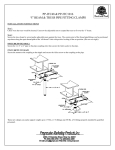
This section provides procedures for the checkout and replacement of the various parts used within the fryer. Before replacing any parts, refer to the Troubleshooting section. It will aid
you in determining the cause of the malfunction.
This section is arranged in groupings of the components that
work together within the fryer. The general groups are listed
below.
Removing the Control Panel
Probe
Electrical Components
Control Board
Pressure System
1. You may want to use a multimeter to check the electric
components.
2. When the manual refers to the circuit being closed, the
multimeter should read zero unless otherwise noted.
3. When the manual refers to the circuit being open, the
multimeter will read infinity.
4. The weights can be removed from the frame to easily
access the rear of cooker.
The following electrical components are described in this
section.
1.
2.
3.
4.
5.
6.
7.
High Limit
Fuse Holders
Power/Pump Switch
Contactors
Heating Elements
Temperature Probe
Complete Control Panel Henny Penny
This high temperature control is a manual reset control which
senses the temperature of the shortening. If the shortening
temperature exceeds 420°F (215OC), this control switch will
open and shut off the heat to the cookpot. When the
temperature of the shortening drops to a safe operation limit,
the control must be manually reset. The reset button is located
above the filter knob in the front of the cooker. This will allow
heat to be supplied to the cookpot.
Before replacing a high temperature limit control, check to
see that its circuit is closed.
The shortening temperature must be below 380°F
(193°C) to accurately perform this check.
1. Remove electrical power supplied to the fryer.
Remove electrical power supplied to the fryer by
unplugging the unit, or by turning off the wall circuit
breaker or electrical shock could result.
2. Remove the control panel.
3. Remove the two electrical
temperature limit control.
wires
from
the high
4. Manually reset the control, then check for continuity
between the two terminals after resetting the control. If
the circuit is open, replace the control, then continue with
this procedure. (If the circuit is closed, the high limit.is
not defective. Reconnect the two electrical wires.)
Remove electrical power supplied to the fryer by
unplugging the unit, or by turning off the wall circuit
breaker or electrical shock could result.
1. If the tube is broken or cracked, the control will open, shutting off electrical power. The control cannot be reset.
2. Drain shortening from the cookpot and discard. A
substance in the tube could contaminate the shortening.
3. Remove control panel.
4. Loosen small inside screw nut on capillary tube.
5. Remove capillary bulb from bulb holder inside the cookpot.
6. Straighten the capillary tube.
7. Remove larger outside nut that threads into pot wall.
8. Remove the two nuts securing the high limit bracket at
the front of the fryer, and remove bracket.
9. Remove the two screws that secure high limit to the high
limit bracket.
10. Remove defective control from control panel area.
Il.
Insert new control and replace screws.
12. Uncoil capillary line, starting at capillary tube, and insert
through cookpot wall.
To avoid electrical shock or other injury, the capillary
line must run under and away from all electrical power
wires and terminals. The tube must NEVER be in such
a position where it could accidentally touch the electrical power terminals.
13. Carefully bend the capillary bulb holder on heating
elements.
14. Slip capillary bulb into bulb holder located on heating
elements. Pull excess capillary line from pot and tighten
nut into cookpot wall.
Be sure capillary bulb of high limit is positioned as not
to interfere with carrier or when cleaning the cookpot
wall, or damage to capillary tube could result.
15. With excess capillary line pulled out, tighten smaller nut.
16. Replace front panel.
17. Refill with shortening.
There are two fuse holders on each model of the electric fryers.
There are no fuse holder assemblies for the gas models other
than that at the main power source.
Remove electrical power supplied to the fryer by
unplugging the unit, or turning off the wall circuit
breaker or electrical shock could result.
CONTROL PANEL FUSES 3 Phase Check from #54 to #55
and #68 to #69 on fuse assembly, or the fuse can be removed
to check for a closed circuit. If not, replace the fuse (HP#
EF02-007).
The Power/Pump
a center “OFF“
position the fryer
position the filter
not.
Switch is a three way rocker switch with
position. With the switch in the POWER
wiil operate. With the switch in the PUMP
pump will operate, but the heating unit will
1. Remove Control Panel.
Remove electrical power suppled to the fryer by unplugging the unit, or turning off the wall circuit breaker
or electrical shock could result.
2. “OFF” Position - should be open circuit anywhere on the
switch.
3. “Power” Position
Check from:
-5 to -6 closed circuit
-1 to -2 closed circuit
4. “Pump” Position
Check from:
#4 to #5 closed circuit
#3 to #2 closed circuit
Check across the jumpers on the wires of the
Power/Pump Switch. These jumpers have resistors and
capacitors which may be faulty.
1. With control panel removed and wires off of the switch,
push in on tabs on the switch to remove from the panel.
2. Replace with new switch, and reconnect wires to switch
following the wiring diagram.
3. Replace the control panel.
The electric fryer requires two switching contactors: a primary
contactor and a heat contactor. The primary contactor
energizes (contacts close) any time the Power/Pump Switch
is in the “Power” position and the temperature of the pot is
below 420°F (215OC). The hi limit will cut the power at the
primary contactor if temperatures in the cookpot exceed 420° F
(215O6). The primary contactor supplies power to one side of
the heat contactors.
The heat contactor is controlled by the computer controller.
en the controller calls for heat, the heat contactor applies
power to one side of the heating elements. When the heat
contactor and the primary contactor are energized (contacts
closed), the electric heating elements heat the shortening.
Primary
Heat
1. Remove electrical power supplied to the fryer.
Remove electrical power supplied to the fryer by
unplugging the unit, or turning off the wall circuit
breaker or electrical shock could result.
2. Remove the control panel.
3. Perform a check on both contactors as follows:
E?SL
Its
L3 - L3
L2 - L2
Ll - Ll
Open Circuit
Open Circuit
Open Circuit
4. Check across the coil terminals:
Standard Contactor - 415 ohms
Mercury Contactor - 1500 ohms
The following checks, are performed with the wall
circuit breaker on, and the Power/Pump Switch in the
ower” position. Extreme caution should be taken.
ake connections before applying power, take reading,
and remove power by unplugging the power cord, or
by turning off the wall circuit breaker, before removing meter leads or electrical shock could result.
5.
ith power re-applied and in a heat-up mode, check the
power going to both contactor coils. This is to be sure
power is going to the contactors.
If no voltage is found going into the coils, the
and drain switch for the primary contactor.
Section.) For the heat contactor, check wi
If either contactor is defective it must be replaced as follows:
Remove electrical power supplied to the fryer by
unplugging power cord or turning off the wall circuit
breaker, or electrical shock could result.
emove only those wires directly connected to the
contactor being replaced. Label the wires.
2. Remove the two mounting screws on the base plate and
remove standard contactor (primary). Proceed to step 5.
3. Remove the two nuts securing the mercury contactor
bracket to the base plate and remove bracket.
4.
move the two screws securing the mercury contactor
the bracket and remove contactor.
5. Install new contactor in reverse order of previous steps.
nstall control panel.
econnect power to fryer and test the fryer for proper
Each electric fryer uses two heating elements.
Heating elements are available for 208 or 220/240,380
and 415 voltage. Check the data plate on the right side
panel of unit to determine the correct voltage.
If the shortening’s temperature recovery is very slow, or at
a slower rate than required, this may indicate defective heating
element(s). A multimeter will quickly indicate if the elements
are shorted or open.
1. Remove electrical power supplied to the fryer.
Remove electrical power supplied to the fryer by
unplugging the unit, or turning off the wall circuit
breaker or electrical shock could result.
2. Remove the Control Panel.
The following checks are performed with the wall
circuit breaker closed and the Power/Pump switch in
“Power” position. Extreme caution should be taken.
Make connections before applying power, take reading,
and remove power by unplugging the power cord, or
by turning off the wall circuit breaker, before removing meter leads, or electrical shock could result.
3. Perform an amp check on one heating element at a time
with the wires connected to the contactors. The two
heaters actually have three small heating elements on the
inside of the outer plate. It is important to check between
the correct wires to obtain an accurate amp reading. The
wires are labelled for your convenience.
L3
L2
Ll
L3
L2
-
L2
Ll
L2
L2
Ll
ower
8500 w
8500 w
8500 w
8500 w
8500 w
8500 w
203
208
208
240
240
240
v
v
V
V
V
V
47.3
47.9
48.0
39.4
40.1
39.9
1. Drain the shortening.
2. Remove the high limit bulb holder from the heating
element.
3. Remove the Control Panel.
4. Disconnect the heating element wires from the contactors.
5. Loosen the screws on the element spreaders.
6. Slide the element spreaders to the back of the heating
elements.
7. Remove the brass nuts and washers which secure the ends
of the elements through the cookpot.
8. Remove the heating elements from the cookpot as a group
by lifting the far end and sliding them up and out toward
the rear of the cookpot.
rings when installing
Always install new
heater elements, or shortening may leak inside cooker.
9. Install new heating elements with new rubber “0” rings
mounted in the center of the stacked elements.
10. Replace the heating elements, terminal ends first at
approximately 45” angle, slipping the terminal ends
through the front wall of the cookpot.
11. Replace the brass nuts and washers on the heating element
terminals.
12.
ove the element spreaders from the back of the elements
to a position which will spread each element apart evenly
on all four sides, and tighten.
13. Replace the high limit bulb holder on the top element, and
position on the bulb above the top element and tighten
screws which hold bulb in place.
14. Reconnect the wires to the appropriate terminals.
15. Replace the front control panel.
16. Connect the power cord to the wall receptacle or turn wall
circuit breaker on.
nergized without
Heating elements shou
shortening in the cookpot, or damage to heating
elements could result.
All fryers are equipped with a drain valve micro-switch that
prevents heat from coming on when the drain valve is open.
With the drain valve open, the switch prevents power from
being applied to the coil of the primary and heat contactors,
and the solenoid coil.
Remove electrical power supplied to the fryer by
unplugging the unit, or turning off the wall circuit
breaker or electrical shock could result.
1. The following check should be made to determine if the
Drain Switch is defective.
a.) Remove the access panel on the right side of the unit.
b.) Remove switch from unit, using 9116” wrench.
c.) Check for continuity across the two outside terminals
on the Drain Switch. If circuit is open, the Drain
Switch is bad. The circuit should only be opened by
pressing on the actuator of the Drain Switch.
2. To replace the Drain Switch, remove the wires from
switch.
3. Connect wires to new
in unit.
rain Switch, and reposition switch
4. Test to see if drain valve extension rod actuates the switch.
NOTE - Listen for CLICK of switch while pulling drain
valve extension rod.
The Temperature Probe relays the actual shortening
temperature to the control. If it becomes disabled, PROB will
show in the display. Also, if the temperature is out of calibration more than loo F or Co, the probe should be replaced as
follows:
1. Remove electrical power supplied to the fryer.
Place the Power Switch to the “OFF” position, and
unplug the power cord or turn the wall circuit breaker
off or electrical shock could result.
I
2. Drain the shortening from the cookpot.
1\.*
Henny Penny
5-11. TEMPERATURE PROBE
REPLACEMENT
(Continued)
Model 580
3. Remove the Control Board.
4. Remove probe connections from PC board.
5. Using a ½” wrench, remove the nut on the compression
fitting.
6. Remove the probe from the cookpot.
7. Place the nut and new ferrule on the new probe and insert
the probe into the compression fitting until it extends
.475 inches (12 mm) into the cookpot.
8. Tighten hand-tight and then a half a turn with wrench.
Excess force damages the probe.
9. Connect new probe to PC board and replace Control
Panel.
10. Replace shortening.
11. Turn power “ON” and check out fryer.
501
5-11
Henny Penny
5-12. COMPLETE CONTROL
PANEL HENNY PENNY
Model 580
Should the Control Panel become inoperative, follow these
instructions for replacing the board.
1. Remove electrical power supplied to the fryer.
Place the Power/Pump Switch in the "OFF" position,
and unplug the power cord and/ or turn the wall circuit
breaker off or electrical shock could result.
2. Remove the two screws securing the Control Panel and
lift panel up and out.
3. Unplug the connectors going to the Control Board.
4. Install a new Control Panel.
When plugging connectors into new Control Panel be
sure connectors are put on in the correct manner, such
as, be sure connector isn't put on backwards.
5-13. PRESSURE REGULATION
The Henny Penny Fryer uses pressure as one of the
components of the cooking process. Once the lid is
sealed to the cookpot, and the solenoid valve closes, a
deadweight valve maintains the correct pressure in the
cookpot.
The lid has minimal and limited maintenance and
repair procedures, which are addressed in the
following sections.
5-12
1005
Henny Penny
Model 580
5-14. PREVENTIVE
MAINTENANCE
The following is a routine maintenance schedule for the Lid:
Every 90 days
• Clean and reverse lid gasket
Yearly Cleaning and Inspection
5-15. REVERSING LID
GASKET
•
Remove and clean Safety Relief Valve
•
Check Lid Gasket for splitting and tears - replace if necessary
•
Check Pressure Pads for wear - rotate if necessary
•
Check Cam Slide Guides - replace if worn or broken
•
Check Lid Rollers - replace if cracked or damaged.
The gray rubber gasket surrounding the inside of the lid is designed
to be reversed. HENNY PENNY RECOMMENDS THIS BE
DONE EVERY 90 DAYS.
Because heat expansion and the pressure used for the cooking
process, the gasket is constantly under extreme stress. Reversing
the lid gasket every 90 days helps to assure the fryer won’t lose
pressure through leakage.
1. Open the lid completely, tilt lid back, and lock lid in place with
the “kickstand”.
2. Using a thin blade screwdriver pry out the gasket at the corners.
Remove the gasket.
“kickstand”
402
5-13
Check the gasket for any tears or nicks. If the gasket
is damaged it needs to be replaced.
Be careful that the lid doesn’t fall down while it is in
the upright position, or serious injury could result.
3. Clean the gasket and gasket seat with hot water.
4. Rotate the gasket with the opposite side facing out.
Begin the installation by installing the four corners of
the lid gasket, and smoothing the gasket into place from
the corners. ,
The Lid Counterweight in the back of the fryer balances the
weight of the lid system to allow easier opening and closing
of the lid. The weight has two cables attached to it, and weighs
). One cable is centered on the weight
about 150 lbs. (67.5
and is the cable being used. The other cable is a safety cable
and is off center. In case the main cable becomes loose or
broken, the safety cable catches the weight and puts the weight
into a bind, not allowing the lid to be opened or closed.
1. Using a 3/8” socket, remove the back shroud of the fryer.
2. With one person holding the weight level, another person
locks the lid down.
3. Unthread the broken cable from the weight and the
bracket attached to the fryer, and remove broken cable.
4. Thread a 506” nut on each end of the new cable.
5. Screw the new cable into the weight, using a wrench, until
it is tight.
6. Using a l/Z” wrench, tighten the nut (already threaded
on the cable) against the weight securing the cable into
the weight.
.\ \ \.,“‘@l$
,” $,#
&i,!
\.,“,,
,;
‘,
ull cable over pulley and down behind the weight.
8. Thread the other end of the cable through a 5/16” nut on
the underside of the bracket.
9. Tighten the cable up by screwing the cable through the
nut, until the weight
becomes level.
-
The safety cable should now have some slack in it, with
the weight level.
10. Tighten the nut against the bracket, securing the cable.
11. Replace the back shroud. Repair is now complete.
Henny Penny
5-17. PRESSURE PAD
Model 580
The pressure pads are plastic strips that the lid cam presses
against to seal the lid.
1. Raise the lid.
2. Remove the four screws securing the lid cover and remove
cover.
3. Push the lid cam back, off of the pressure pads.
4. Using an Allen wrench, remove large bolt securing the pad.
5. Using a Phillips head screw driver, remove the small screw
securing the pad and remove the broken pad.
NOTE
If the pressure pad is worn, but not broken, it can be
reversed 180 degrees, and the other end of the pad used.
6. Install new pad in reverse order.
5-16
302
Henny Penny
5-18. LID ADJUSTMENT
Model 580
If steam leaks out from around the lid gasket, the pressure pads
could be worn or broken. If the pressure pad is worn, but not
broken, it can be reversed 180 degrees, and the other end of the
pad used. See Section 5-17.
Other problems could cause the steam to leak, such as a
cracked or worn gasket, or gasket not installed properly.
Be certain leaking is not caused by too much pressure
before making any lid adjustments. Fryer should be
operating at 12 psi. Refer to Operating Control Valve
section. All these areas should be checked, or serious burns
could result.
302
5-17
ith the carrier and racks installed on the lid, the lid should
down, in contact with the pot rim, when the lid is lowered.
The user will then be able to lock the lid in place. If the lid
has a tendency to rise up before getting t
the magnet plate probably needs adjusting
emove the six nuts securing the back shroud and remove
back shroud.
2. Loosen the bottom nut under the plate and unscrew both
nuts a couple turns, then lower the lid again to see if the
lid stays down. If not, repeat procedure.
3.
ten lower nut up against the other nut and install back
shroud - adjustment is now complete.
This is an electromechanical device that causes pressure to be
held in the cookpot. The solenoid valve closes at the beginning
of the cook cycle and opens automatically at the end of the
cook cycle. If this valve should become dirty, or the Teflon seat
nicked, pressure will not build up. The electric fryer uses a
208/240 volt, 60 hertz coil (50 hertz internationally).
starting
repair p
ump Switch to the ‘
nect main circuit breaker at the circuit breaker box
and/or unplug service cord from the wall receptacle or
electrical shock could result.
Remove the solenoid wires from the wire nuts which are found
behind the control panel. Check across wires.
2081240 Volt, 60
2081240 Volt, 50
230 Ohms
rior to servicing the solenoid valve, it is necessary to
remove the side panel on the right side of the unit.
1. Remove the “tru-arc”
housing.
retaining clip on top of the coil
2. Remove the cover.
3. If only the coil is to be replaced, disconnect the two coil
wires at the wire nuts in the coil housing.
insert new coil, and connect the wires at the wire nuts.
Assemble in reverse order of disassembly.
The wires may be connected in any order.
4. Loosen the screws on the strain relief and pull the wires
through the relief.
5. If the core-disc assembly is sticking due to build-up of
shortening, breading, and food particles, proceed with the
following steps:
a. Unscrew the solenoid bonnet assembly from the
solenoid valve body.
emove the solenoid bonnet assembly and bonnet
gasket.
c. Remove the core-disc assembly, core spring retainer,
and the core spring.
d.
ash all these parts in hot water.
If Teflon seals need to be replaced, proceed to Step 6;
otherwise, assemble in reverse order of disassembly.
Assemble valve core and blade with smooth side and
rounded edge of blade toward the disc spring guide.
6. A repair kit (Part No. 17120) is available if any of the seals
must be replaced. If any one seal is defective, they all
should be replaced.
Solenoid body must be removed from the fryer for
replacement of seals.
Henny Penny
5-20. SOLENOID VALVE
Replacement (Continued)
Model 580
7. With the bonnet assembly and core-disc assembly
removed, disconnect the two nut fittings. One connects
the solenoid valve to the dead weight system; the other is
attached to the condensation tank.
8. Remove the elbows from the solenoid valve.
9. Remove the two adapter screws which attach the pipe
adapter to the solenoid valve body.
10. Remove the disc spring, guide, and Teflon seat.
11. Clean the valve body.
12. Wet “O” ring around seat with water and insert “O” ring
assembly (flat side first) in valve through “IN” side of
body. Use an eraser end of pencil and press in the Teflon
seal until it snaps into place. BE CAREFUL NOT TO
MAR OR NICK THE SEAT.
NOTE
The smallest nick can cause a pressure leak. Replace all
“O” ring seals that are in the parts kit and reassemble
valve.
13. If the complete valve is being replaced, follow steps 1, 2,
3, 4, 5, 7, and 8, in this section.
5-21. OPERATING CONTROL
VALVE
DO NOT ATTEMPT TO REMOVE THE VALVE CAP
WHILE THE FRYER IS OPERATING, or severe burns
or other injuries could result.
The operating valves are located at the back of the unit. The
valve left of the pressure gauge is a 14 ½ lb. safety relief valve,
and to the right of the pressure gauge, the operating valve.
Valves are working properly, when “OPERATING ZONE”
indicates on the gauge by the pointer. The gauge pointer
should not normally exceed the operating zone. If the pressure
builds to 14 ½ lbs., the safety relief valve opens and releases
pressure from the frypot.
5-20
1200
Henny Penny
Model 580
5-21. OPERATING CONTROL
VALVE (Continued)
DO NOT MANUALLY ACTIVATE THE SAFETY
RELIEF VALVE. Hot steam will be released from the
valve when the ring is pulled. Keep away from safety
valve exhaust, or severe burns could result.
Cleaning Steps
ORIFICE
1.
CAP
WEIGHT
AT THE END OF EACH DAY’S USAGE OF THE
FRYER, THE OPERATING VALVE MUST BE
CLEANED. The fryer must be OFF and the pressure
released. Open the lid and then remove the dead weight
valve cap and dead weight.
Failure to clean the operating valve daily could result in
the fryer building too much pressure. Severe injuries and
burns could result.
5-22. REMOVAL & CLEANING
OF SAFETY VALVE
2.
Wipe both the cap and weight with a soft cloth. Make
certain to thoroughly clean inside cap, the weight seat, and
around valve orifice.
3.
Dry the parts and replace immediately to prevent damage
or loss.
The safety relief valve should be cleaned once a year.
SAFETY VALVE
Do not attempt to remove valve while fryer is operating,
or severe burns or other injuries could result.
1. Remove pressure gauge.
2. Use a wrench to loosen the valve from the elbow, turn
counterclockwise to remove.
402
5-21
Henny Penny
5-22. REMOVAL & CLEANING
OF SAFETY VALVE
(Continued)
Model 580
3.
Clean inside of the elbow with hot water.
NOTE
Turn the relief valve towards the left side of the fryer
when reinstalling relief valve.
4.
Immerse the safety relief valve in soapy water for 24
hours. Use a 1 to 1 dilution rate. The valve cannot be
disassembled. It is factory preset to open at 14 ½ pounds
of pressure. If it does not open or close, replace it!
DO NOT DISASSEMBLE OR MODIFY THIS VAVLE!
Tampering with this valve could cause serious injuries and
also voids agency approvals and appliance warranty.
5-23. PRESSURE GAUGE
Calibration Steps
PRESSURE GAUGE
Cleaning Steps
5-22
Recalibrate the pressure gauge if it is out of adjustment.
1.
Remove the rim and glass.
2.
If the indication hand shows a pressure or vacuum reading
when it should stand at “0”, turn the recalibrator screw in
the same direction in the indicating hand is to be moved
until the hand stands at proper “0” position.
3.
Replace the rim and glass.
1.
Remove the gauge and check inside the pipefittings from
dead weight body. Make certain fittings are clean and
open.
2.
Clean and reinstall the gauge.
402
The drain valve is found underneath the cookpot in the back
of the fryer. It is opened by pulling the red knob in the front
of the fryer, allowing the shortening to drain from the cookpot.
1.
rain the shortening from the cookpot.
2. Remove right side panel of fryer.
emove the two cotter pins from the drain valve fitting
and drain rod and pull extension from the drain valve, and
let rod drop down.
4. Unscrew the drain shield from the valve.
5. Unscrew drain valve from the cookpot.
6. Replace new drain valve in reverse order.
The nylatron strips fiil the gap in the shroud behind the lid.
1. Secure the lid with the lid stop bracket.
emove one of the tru-arc rings off of the lid pin and knock
the pin out of the lid.
3. Lift the lid from the unit.
The lid weighs 80 lbs. Care should be taken when lifting
the lid to prevent personal injury.
4. With one person on each lid arm, release arms from the
lid stop bracket and allow lid arms to rise all the way up.
5. Using a 318” socket remove the nuts securing the back
shroud and remove the back shroud.
6. Remove bolts securing the strips to the weights, and
remove strips from weights.
7. Remove the screws securing the front shroud.
8. Lift the front shroud up and out, over the arms of the lid.
9. Thread the new nylatron strip through the track in the
front shroud.
10. Lining up the holes in the strips, fit the front shroud over
the lid arms and secure to carriage frame.
2