1
GAS MONITORS
MODELS 2050-00 & 2050-10
MODELS 2060-00 & 2060-10
GAS MONITORS
MODELS 2050-00 & 2050-10
MODELS 2060-00 & 2060-10
APPLICABILITY & EFFECTIVITY
This manual provides instructions for the following Sierra Monitor products:
Model
2050-00
2060-00
Description
Ammonia Gas Monitor
Halocarbon Gas Monitor
The instructions are effective for the above models as of January 1, 2004
Instruction Manual Part Number T10013
Rev. C
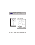
TABLE OF CONTENTS
SECTION
PAGE
1.PRODUCT DESCRIPTION
1.1 Introduction
1.2 Application
1.3 Configuration
1.4 Temperature Range
1.5 Sensor
1.6 Remote Alarm
1
1
1
1
2
2
2
2. QUICK START
2.1 Overview
2.2 Wiring
3
3
3
3. OPERATION
3.1 Introduction
3.2 Alarms
3.3 Outputs
4
4
4
4
4. ALARM CALIBRATION
4.1 Factory Alarm Calibration
4.2 Frequency of Alarm Calibration Check
4.3 Alarm Calibration Check Process
4.4 Equipment Required
4.5 Alarm Calibration Procedure
5
5
5
5
6
6
5. SERVICE
5.1 Sensor Replacement
7
6. INSTALLATION
6.1 Gas Sensor Module Locations
6.2 Mounting
6.3 Wiring
6.4 Power Supply
6.5 Alarm Devices
8
8
8
8
8
8
7. ALARM CONFIGURATION
10
8. SPECIFICATIONS
11
9. ACCESSORIES AND REPLACEMENT PARTS
11
10. LIMITED WARRANTY
11
Table of Contents
Instruction Manual
1.0 PRODUCT DESCRIPTION
1.1 Introduction
The Model 2050 Ammonia and Model 2060 Refrigerant/
Halocarbon Gas Monitors are continuous duty, low cost
stationary monitors for detection of high levels (50-500
PPM) of ammonia and halocarbon ("freons") refrigerant
gases. See the specifications page for a full list of available applicable halocarbons
This manual provides instructions for both the 2050 and
2060 series Gas Monitors, including the relay versions.
1.2 Application
These monitors are primarily used in and around freezers, refrigerators, and compressor rooms to warn of leaks
and dangerous levels of these gases.
1.3 Configuration
Model
2050-00
2060-00
Gas
Ammonia
Halocarbons
TTL
X
X
Relay
X
X
Table 1.1 Gas Monitor Configurations
factory setpoint for R12 is 500 ppm while the setpoint
for R134 a is 50 ppm. See the specifications for more
details.
The Model 2050 / 2060 is cross sensitive to other combustible gases. If combustible gasses in excess of 50
ppm are expected in the area please contact Sierra Monitor to determine amount of cross-sensitivity expected
for the specific combustible gas. It is not recommended
to use this unit in areas with combustible gases present.
An alarm is activated when the concentration of gas
exceeds the user-adjustable level. An alarm condition
activates the alarm light on the front of the monitor and
generates an output signal. On Models 2050-00 and the
2060-00 the output signal a TTL (Transistor-Transistor-Logic signal) can activate a remote alarm through
one of Sierra Monitor’s Alarm Panels. (The Model 2102
Dual Channel Alarm Panel can be connected up to 500
feet from the monitors. ) The models can be configured with a 0.5 amp, dry contact relay.
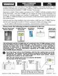
The monitors are housed in a
polystyrene enclosure that is suitable for installation in freezer, refrigerator or other applications.
Test connections and adjustment
controls are located on the outside of the enclosure and are easily used, even when the operator
is wearing hand protection.
The Model 2050 Ammonia monitor has a factory alarm setpoint of
100 ppm NH3. This setpoint is
user adjustible in the field over a
range of 50 to 500 ppm NH3. The
Model 2050 calibration can be
checked with Hydrogen gas.
The Model 2060 Halocarbon
monitor can be calibrated with
carbon monoxide and the factory
setpoint varies for the specific
type of halocarbon present. The
Page: 1
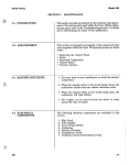
Figure 1.1 Outline View - 2050/2060 Series
2050/2060 Gas Monitors (5/04)
Instruction Manual
1.4 Temperature Range
The Model 2050 and 2060 have temperature compensated circuitry to provide stabilization in temperatures
ranging from -4o to 158oF.
However, for optimum operation the unit should be calibrated at the normal temperature expected for the sensor
location.
1.5 Semiconductor-Type Sensor
A solid-state semiconductor-type sensor and associated electronic circuitry ensure trouble-free, long-term
operation. All the electronic circuitry needed to operate
the monitor, except the DC input power, is contained in a
compact unit. There are no pumps, filters, or chemical
cells to replace or maintain. Except for periodic calibration to verify the alarm setting, no attention is required
after installation. The user may adjust the alarm level by
applying a different calibration gas concentration.
A sensor self-check feature will flash the alarms on and
off alternatively should the sensor fail (open circuit).
The alarm flash includes LEDs, audible alarm, relay or
alarm signal as applicable.
1.6. Remote Alarm Available
If a remote alarm is desired, Sierra Monitor’s Alarm Panels, the Model 2102 Dual Channel Alarm Panels can be
connected up to 500 feet away from the monitors.
2050/2060 Gas Monitors (5/04)
Page:
2
Instruction Manual
2.0 QUICK START
2.1 Overview
The Gas Sensor Module has been supplied factory
calibrated and ready for immediate installation and
operation. An installer familiar with installation and
operation of gas detection products can use this
section to begin immediate use of the monitor.
2.2 Wiring
Each module requires four-conductor wiring (two
wires for power and two wires for the signal).
During warm-up the monitor will, first, cycle
through safe/alarm/safe condition at one hertz.
This will be followed by a short period of continuous alarm before warm-up is completed.
2.2.4 Configuration
The default configuration for each module is to
operate with a buzzer and a normally operating
open (NOO) relay. The user can change this configuration using the jumpers provided. Refer to
table 6.2.
2.2.1. Model 2050-2060 Series
The Model 2050-2060 series are designed to
mount on any indoor vertical surface. Mount
the monitor in the desired location.
-
The installation must meet any hazardous environmental codes for AC/DC electrical instrumentation.
2.2.2 Wiring Connection
Terminal positions on the electronics board are
as follows:
Term inal
TB1-1
TB1-2
TB2-1
TB2-2
TB2-3
Function
+ VDC (9 – 24)
GND (0VDC)
Relay NC (Norm ally Closed) or
Output to Model 2102 Safe
Relay Com mon
Relay NO (Norm ally O pen) or
Output to Model 2102 Alarm
Table 2.1
2.2.3 Start-up & Operation
To begin operation of the Gas Sensor Module
provide 9 - 24 VDC from a regulated power
supply such as one of the Sierra Monitor Alarm
Panels, 2102-XX. Each time the sensor module is powered up it will perform a warm-up for
2 - 60 minutes.
Page: 3
2050/2060 Gas Monitors (5/04)
Instruction Manual
3.0 OPERATION
3.1 Introduction
Trouble Alarm
Under normal conditions the gas sensor module does
not require operator or technician intervention. The
following are conditions under which the module requires attention:
- Routine periodic calibration
- Sensor replacement on a planned schedule
or when a sensor failure occurs.
- Periodic cleaning as necessary.
Interrupted contact closure and “red/green” visual indication (once the warm-up time is completed) after unit has been in operation, indicating either a failed sensor or calibration problems.
Buzzer
Relay
Relay
Fail Safe
On/Off
Oscilating
Oscilating
3.2 Alarms
Three alarm conditions are possible. These can be
detected visually at the optional Sierra Monitor controller and at the module.
Warm-Up Alarm
Oscillating (On/Off) contact closure and “red/
green” visual indication when power is first connected to the module, followed by a continuous
closure of approximately 2-60 minutes indicating warm-up.
Buzzer
On/Off
Relay
Oscilating
Relay
Fail Safe
Oscilating
3.3 Outputs
For the non-relay configurations a 5 volt DC TTL
signal is provided to activate remote alarms such
as the Sierra Monitor Alarm Panels. Relay configuration alarm conditions described above are transmitted to the annunciator as relay contact closures
from the monitor.
The alarm outputs are non-latching closed contacts.
As soon as the gas concentration falls below the
alarm set-point, the alarm will stop and the alarm
output will cause the relay to de-energize and the
contacts will open.
During warm-up and failed sensor alarms the relays contact and the display LED's oscillate at approximately one hertz.
Gas Alarm
Sustained contact closure and solid red light
(once the warm-up time is completed) indicating the presence of gas at, or above, the pre-set
alarm limit.
Table 2.1
Buzzer
Relay
Relay
Fail Safe
On
Closed
Open
2050/2060 Gas Monitors =(5/04)
Page: 4
Instruction Manual
4.0 ALARM CALIBRATION
4.1 Factory Alarm Calibration
The module has been factory calibrated to alarm as
indicated in Table 4.1 and as marked on the calibration label shipped with the module.
Model
Time
Gas
cc/min
2050-XX
100 sec. 100 ppm NH3
50
2060-XX
60 sec. 500 ppm R11
500 ppm R12
50 ppm R22
100 ppm R113
70 ppm R123
50 ppm R134a
40 ppm R141b
40 ppm R142b
40 ppm R500
70 ppm R502
50
50
50
50
50
50
50
50
50
50
Table 4.1
4.2 Frequency of Alarm Calibration Check
The manufacturer recommends that the calibration
of each gas sensor module be verified monthly during the first three months of operation and then quarterly. More frequent checks are necessary during
periods of extreme humidity and temperature
changes. The monitor should have operated continuously (uninterrupted) for at least 24 hours prior
to calibration adjustment.
4.3 Alarm Calibration Check Process
The output signal of the gas sensor module is calibrated
using a calibration gas mixture containing a known
concentration of the gas of interest and a balance of air,
or using a substitute gas. The concentration of the span
gas must be equal to the alarm point desired.
The equivalent substitute gas is 80 ppm Hydrogen (H2)
for the Model 2050 and 150 ppm Carbon Monoxide
(CO) for the Model 2060.
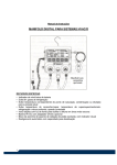
Calibration requires application of the span gas to the
sensor and adjustment of the sensitivity adjustment potentiometer.
Warning: During calibration the alarm will turn on and
remote alarms connected to the alarm relays will be
activated. Disable the remote alarm if necessary.
Fig. 4-1 Location of Calibration Voltmeter Connections and Adjustments
Page:
5
2050/2060 Gas Monitors (5/04)
Instruction Manual
4.4 Equipment Required
The following tools and equipment will be required for
calibration:
- Jewelers Screwdriver
- Calibration Gas
- Calibration gas delivery system
For accurate calibration use a gas mixture at the required concentration mixed in an air balance, rather
than with an inert gas like nitrogen. This gas and the
required delivery equipment such as the Model 120026 Calibrator is available from Sierra Monitor Corporation.
4.5 Alarm Calibration Procedure
1.
The monitor should be in the safe condition prior
to calibration (green LED “ON”).
- Be sure that the area is non-hazardous before proceeding.
2.
With the monitor in operation, expose the sensor
to a sample of calibration gas. Apply calibration
gas directly to the sensor insuring that the delivery
cup loosely covers the sensor. Use 80 PPM H2 for
the Model 2050 and 150 PPM CO for the Model
2060.
3.
The red LED on the face of the monitor should turn
"on". If the alarm occurs within 18-20 seconds and
stops within one minute of the removal of the calibration gas, the monitor is in calibration and requires no further adjustment.
4.
If the monitor fails to alarm within 90 seconds of
the application of the gas adjust the potentiometer
counter clockwise until the alarm turns "on".
5.
If the monitor fails to stop alarming within one
minute of the removal of the gas adjust the potentiometer clockwise until the alarm stops.
6.
After adjustment, repeat steps 4 and 5 to verify calibration.
7.
When the calibration is complete, reconnect any
alarm equipment as necessary.
2050/2060 Gas Monitors (5/04)
Page:
6
Instruction Manual
5.0 SERVICE
5.1 Sensor Replacement
The gas sensor needs replacement when:
-
-
-
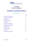
3. Unplug the sensor connector on the lower
right hand corner of the electronics board.
It is no longer possible to obtain correct
calibration
4.
Unscrew the sensor assembly from the end of the
enclosure.
The failed sensor alarm (oscillating
red/green LED) is on
5.
Reverse the preceding steps to install the new sensor assembly.
The sensor output signal is noisy,
causing incorrect gas alarms.
6.
Restore power and allow a minimum of 24 hours
for stabilization before recalibration. The calibration should be re-verified after 6 days of continuous operation.
To replace the sensor:
1.
2. Remove the cover from the main enclosure.
Confirm that the system power has been
removed.
Figure 5-1 Model 2050/2060 Electronics Board Connections
Page:
7
2050/2060 Gas Monitors (5/04)
Instruction Manual
6.0 INSTALLATION
6.1 Gas Sensor Module Locations
The gas sensor module is a diffusion type sensor
that should be located close to the anticipated source
or destination of the gas hazard. For heavy gases
such as H2S install the module within 24 inches of
the ground. For lighter gases such as CO and combustible gases use a higher elevation.
After optimum locations are determined based on
the above recommendations, consideration should
be given to placing the sensors in locations that are
accessible for calibration service. Slight adjustments
to the location of the sensor may have little impact
on effectivity but major effect on accessibility.
6.4 Power Supply
The power supplied by the controlling device or an
external power supply must meet the following specifications:
Voltage:9 - 24 VDC
Current: 250 mA
6.5 Alarm Devices
The internal relay is rated at 0.5 Amp, normally open
dry contact rated at 100 VDC/130 VAC.
6.2 Mounting
To mount the monitor, remove the four svrews in the
cover plate and move the cover plate aside. Use
screws through the monitoring holes visible in the
four corners of the housing to mount the monitor to
a wall.
- The installation must meed any hazardous environmental codes for AC/DC electrical instrumentation.
6.3 Wiring
Interconnect wiring from the controller to the module
is by 4 conductor 22 AWG (or lower AWG) cable,
conduit as necessary. Shielding is not required.
For installations where the distance from the controller to the sensor is greater than 500 feet, 18
AWG cable is recommended.
Terminal
TB1-1
TB1-2
TB2-1
TB2-2
TB2-3
Function
+ VDC (9 – 24)
GND (0VDC)
Relay NC (Normally Closed) or
Output to Model 2102 Safe
Relay Common
Relay NO (Normally Open) or
Output to Model 2102 Alarm
Table 6.1
The terminal strip on the electronics board in the
module. The wiring must be connected as indicated in Figure 6.1 depending upon the controller
or relay configuration being used.
2050/2060 Gas Monitors (5/04)
Page:
8
Instruction Manual
Figure 6.1
Interconnect Wiring Table
Page: 9
2050/2060 Gas Monitors (5/04)
Instruction Manual
7.0 ALARM CONFIGURATION
M ode l 20X or 200X Configure d w ith Ala rm Re la y Output
Configura tion Jum pe rs
Relay Operation
B uzzer A ctive
Norm ally
Norm ally
Y es
No
Not E nergized
E nergized
Default
Default
Ins tall Jum per Rem ove Jum per
Install Jum per
Install Jum per
JP 6
JP 6
JP 2 pins 1-2
JP 2 pins 2-3
(B est for 20X)
W iring Te rm ina tions
P ower S upply
Output Term inals
TB 1-1
TB 1-2
TB 2-1
TB 2-2
TB 2-3
+ DCV
0 DC
NC
Com m on
NO
(9-24 V DC)
Com m on
M ode l 20X or 200X Configure d for Inte rfa ce to M ode l 2102 Ala rm P a ne l
Configura tion Jum pe rs
B uzzer A ctive
Relay Operation
Interface S election
Norm ally
Norm ally
Y es
No
M odel 2102
Not E nergiz ed
E nergized
Default
Default
Ins tall Jum per Rem ove Jum per
N/A
N/A
Install Jum pers
JP 6
JP 6
JP 3 pins 1-2
(B est for 20X)
JP 2 pins 1-2
P ower S upply
TB 1-1
TB 1-2
+ DCV
0 DC
To M odel 2102 To M odel 2102
Term inal J5 -2 Term inal J5 -3
or J6-2
or J6-3
W iring Te rm ina tions
Output Term inals
TB 2-1
TB 2-3
S afe
A larm
To M odel 2102
To M odel 2102
Term inal J5 -1 Term inal J5 -4 or
or J6-1
J6-4
TB 2-2
Not Used
Ta ble 6.2
Jum pe r Configura tion a nd W iring Te rm ina tions
No Power
Sensor Fail
Safe
Alarm
No Power
Sensor Fail
Safe
Alarm
2050/2060 Gas Monitors (5/04)
Relay Operation
Normally Not Energized
TB2-1 NC
TB2-2 Common
TB2-3 NO
Open
Connected
Oscillating
Open
Connected
Connected
Open
Normally Energized - Fail Safe
TB2-1 NC
TB2-2 Common
TB2-3 NO
Connected
Open
Oscillating
Open
Connected
Connected
Open
Table 6.3
Relay Operating States
Page: 10
Instruction Manual
8.0 SPECIFICATIONS
Indicators:
Green LED for Monitor “ON”/Safe
Red LED for Alarm
Calibration Gas:
2050 Series
2060 Series
80 ppm Hydrogen (H2)
150 ppm Carbon Monoxide (CO)
Sensor Type:
Solid-state metal oxide semiconductor
Power:
9 VDC, 250 mA
Alarm Setpoint::
2050 Series
2060 Series
Signal Output::
2050-00/2060-00
100 ppm NH3
R11
R12
R22
R113
R123
R134a
R141b
R142b
R500
R502
500 ppm
500 ppm
50 ppm
100 ppm
70 ppm
50 ppm
40 ppm
40 ppm
40 ppm
70 ppm
Response Time:
Nominal 5 volt DC, source 25 mA.
SAFE and ALARM Signals
0.5 AMP dry contact, 100 VDC, 130
VAC
Less than 90 seconds
Operating Temperature Range:
-4o to 158oF (-20o to 70oC)
Enclosure Material:
Polystyrene
Size:
5.6 x 3.1 x 2.1 in.
(14.2 x 7.9 x 5.3 cm)
Weight:
0.3 lb (0.15 Kg)
User adjustable with calibration over
range of 50 to 500 ppm
9.0 ACCESSORIES AND REPLACEMENT PARTS
Alarm Panels
Model 2102-00 Alarm Panel - 2 channel
Model 2102-01 Alarm Panel - 2 channel with audible
Replacement parts
SPF22073
Sensor for 2050-XX
SPF22074
Sensor for 2060-XX
Calibration Accessories
1200-26 Gas Sensor Calibrator w/2 gas cylinders
(specify gas type/conc)
1290-10 Gas Cylinder - Carbon Monoxide 150 PPM
1290-11 Gas Cylinder - Hydrogen 80 PPM
10.0 LIMITED WARRANTY
SIERRA MONITOR CORPORATION warrants its products
to be free from defects in workmanship or material under
normal use and service for two year after date of shipment.
SMC will repair or replace without charge any equipment
found to be defective during the warranty period. Final
determination of the nature and responsibility for defective
or damaged equipment will be made by SMC personnel.
All warranties hereunder are contingent upon proper use in
the application for which the product was intended and do
not cover products which have been modified or repaired
without SMC approval or which have been subjected to
accident, improper maintenance, installation or application,
or on which original identification marks have been removed or altered. This Limited Warranty also will not apply
to interconnecting cables or wires, consumables (ie. calibration gases, batteries), nor to any damage resulting from battery leakage.
Page: 11
In all cases SMC’s responsibility and liability under this
warranty shall be limited to the cost of the equipment. The
purchaser must obtain shipping instructions for the prepaid
return of any item under this warranty provision and compliance with such instruction shall be a condition of this
warranty.
Except for the express warranty stated above, SMC disclaims
all warranties with regard to the products sold hereunder
including all implied warranties of merchantability and fitness and the express warranties stated herein are in lieu of all
obligations or liabilities on the part of SMC for damages
including but not limited to consequential damages arising
out of/or in connection with the use or performance of the
product.
2050/2060 Gas Monitors (5/04)