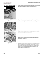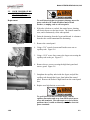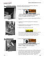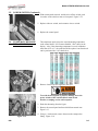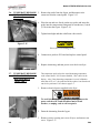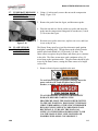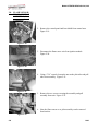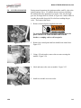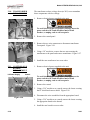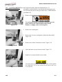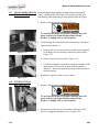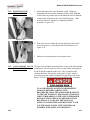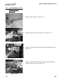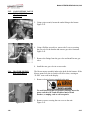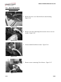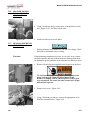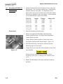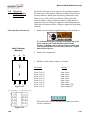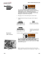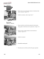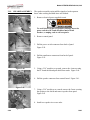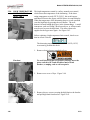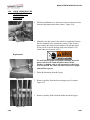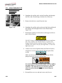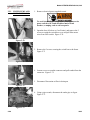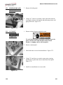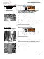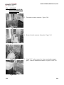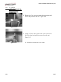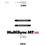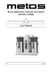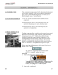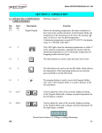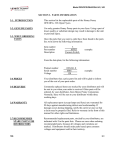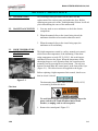
1
Model OFE/OFG/OEA/OGA-341, 342
SECTION 2. MAINTENANCE
2-1. INTRODUCTION
This section provides procedures for the check out and
replacement of the various parts used within the fryer. Before
replacing any parts refer to the Troubleshooting Section. It will aid
you in determining the cause of the malfunction.
2-2. MAINTENANCE HINTS
1. You may need to use a multimeter to check the electric
components.
2. When the manual refers to the circuit being closed, the
multimeter should read zero unless otherwise noted.
3. When the manual refers to the circuit being open, the
multimeter will read infinity.
2-3. HIGH TEMPERATURE
LIMIT CONTROL
(Gas Units)
This high temperature control is a safety, manual reset control,
which senses the temperature of the shortening. If the shortening temperature exceeds 425°F (218°C), this switch opens
and shuts off heat to the frypot. When the temperature of the
shortening drops to a safe operation limit, the control must be
manually reset by pressing the red reset button. The red reset
button is located under the control panel, in the front of the fryer.
(Figure 2-1). This allows heat to be supplied to the frypot.
Before replacing a high temperature limit control, check to see
that its circuit is closed.
Figure 2-1
The shortening temperature must be below 380°F (193°C)
to accurately perform this check.
Checkout
To avoid electrical shock or property damage, move the
power switch to OFF and disconnect main circuit
breaker, or unplug cord at wall receptacle.
1. Remove the control panel. Figure 2-2.
Figure 2-2
1003
2-1
Model OFE/OFG/OEA/OGA-341, 342
1-3. HIGH TEMPERATURE
LIMIT CONTROL
(Gas Units) (Continued)
2. Using a Phillip’s head screwdriver, remove the screws securing
the inner heat shield and remove from unit. Figure 2-3.
Figure 2-3
3. Remove the screw securing the high limit bracket to the frame
and remove the high limit and bracket from unit. Figure 2-4.
Figure 2-4
4. Remove the two screws securing the high limit to the bracket
and remove the high limit from bracket.
5. Remove the two electrical wires from the high temperature
limit control. Figure 2-5.
Figure 2-5
6. Manually reset the control, then check for continuity between
the two terminals after resetting the control. If the circuit is
open, replace the control, then continue with this procedure.
(If the circuit is closed, the high limit is not defective. Reconnect the two electrical wires.)
2-2
1003
Model OFE/OFG/OEA/OGA-341, 342
2-3. HIGH TEMPERATURE
LIMIT CONTROL
(Gas Units) (Continued)
Replacement
To avoid electrical shock or property damage, move the
power switch to OFF and disconnect main circuit
breaker, or unplug cord at wall receptacle.
1. If the tube is broken or cracked, the control opens, shutting
off electrical power to the heat circuit. The control cannot be
reset, and it continuously clicks when pushed.
2. Drain the shortening from the frypot and discard. A substance
from the tube could contaminate the shortening.
Figure 2-6
3. Remove the control panel.
4. Using a 5/16” wrench, loosen small inside screw nut on
capillary tube. Figure 2-6.
5. Using a 11/16” crows-foot, remove the larger nut securing the
capillary tube to the pot. Figure 2-7.
Figure 2-7
6. Remove the two screws securing the high limit guard and
remove guard. Figure 2-8
7. Straighten the capillary tube inside the frypot, and pull the
capillary tube through the frypot, from behind the control
panel. Remove the defective high limit from the control panel
area.
8. Replace new high limit in reverse order.
Figure 2-8
To avoid electrical shock or other injury, run the
capillary line under and away from all electrical power
wires and terminals. The tube must never be in such a
position where it could accidentally touch the electrical
power terminals.
1003
2-3
Model OFE/OFG/OEA/OGA-341, 342
2-4. COMPLETE CONTROL
PANEL REPLACEMENT
Should the control board become inoperative, follow these
instructions for replacing the board.
1. Remove electrical power supplied to the unit.
To avoid electrical shock or property damage, move the
power switch to OFF and disconnect main circuit
breaker, or unplug cord at wall receptacle.
Figure 2-9
2. Remove the two screws securing the control panel and lift out.
Figure 2-9.
3. Unplug the wire connectors going to the control panel.
Figure 2-10.
4. Remove transformer(s) from control panel. They must be
installed on the replacement panels.
5. Install new control panel in reverse order.
Figure 2-10
2-5. POWER SWITCH
When plugging connectors onto new control panel, be sure the
connectors are inserted onto all of the pins, and that the
connectors are not forced onto the pins backwards. If not
connected properly, damage to the board could result.
1. Remove electrical power supplied to fryer.
To avoid electrical shock or property damage, move the
power switch to OFF and disconnect main circuit
breaker, or unplug cord at wall receptacle.
2. Remove control panel.
Figure 2-11
2-4
3. Label and remove wires from the switch. With test instrument
check across the terminals of the switch with switch in the on
position, and the circuit should be closed. In the off position,
the circuit should be open. If the switch checks defective,
replace by continuing with this procedure. Figure 2-11.
504
Model OFE/OFG/OEA/OGA-341, 342
2-5. POWER SWITCH (Continued)
4. With control panel removed, and the wires off the switch, push
in on tabs on the switch to remove from panel. Figure 2-12.
5. Replace with new switch, and reconnect wires to switch.
6. Replace the control panel.
Figure 2-12
2-6. TEMPERATURE PROBE
REPLACEMENT (Gas)
The temperature probe relays the actual shortening temperature
to the control board. If it becomes disabled, “E06” shows in the
display. Also, if the shortening temperature is out of calibration
more than 10°F or C°, the probe should be replaced. An Ohm check
can be performed also. See chart below.
1. Remove electrical power supplied to the fryer.
Figure 2-13
To avoid electrical shock or property damage, move the
power switch to OFF and disconnect main circuit
breaker, or unplug cord at wall receptacle.
2. Drain the shortening from the frypot.
3. Remove the control panel and heat shield from control area.
Figure 2-13.
Figure 2-14
806
4. Using a ½ inch wrench, remove the nut on the compression
fitting. Figure 2-14.
2-5
Model OFE/OFG/OEA/OGA-341, 342
2-6. TEMPERATURE PROBE 5. Remove the probe from the frypot, and disconnect wire
REPLACEMENT (GAS)
connector from the control panel. Figure 2-15.
(Continued)
6. Place the nut and new ferrule on the new probe and insert the
probe into the compression fitting until it extends one (1) inch
(2.54cm) into the frypot. Figure 2-16.
7. Tighten hand tight and then a half turn with wrench.
Figure 2-15
Excess force will damage probe.
8. Connect new probe to PC board and replace control panel.
9. Replace shortening, and turn power on to check out fryer.
Figure 2-16
2-7. TEMPERATURE PROBE
REPLACEMENT (Gas)
REPLACEMENT
(ELECTRIC)
The temperature probe relays the actual shortening temperature
to the control board. If it becomes disabled, “E06” shows in the
display. Also, if the shortening temperature is out of calibration
more than 10°F or C°, the probe should be replaced. An Ohm check
can also be performed. See chart on page 2-5.
1. Remove electrical power supplied to the fryer.
To avoid electrical shock or property damage, move the
power switch to OFF and disconnect main circuit
breaker, or unplug cord at wall receptacle.
2. Drain the shortening from the frypot.
Figure 2-17
2-6
3. Remove screws securing rear cover of fryer, and remove rear
cover. Figure 2-17.
1209
Model OFE/OFG/OEA/OGA-341, 342
2-7. TEMPERATURE PROBE 4. Using a ½ inch wrench, remove the nut on the compression
REPLACEMENT
fitting. Figure 2-18.
(ELECTRIC) (Continued)
5. Remove the probe from the frypot, and disconnect probe.
6. Place the nut and new ferrule on the new probe and insert the
probe into the compression fitting until it extends one (1) inch
(2.54cm) into the frypot.
Figure 2-18
2-8. FLAME SENSOR/
PILOT / IGNITOR
ASSEMBLY (GAS)
7. Reconnect new probe onto wires, replace rear cover, and fryer
is now ready for use.
The Henny Penny open fryer (gas) has electronic spark ignition
that lights a standing pilot. The gap between the spark electrode
and the pilot hood should be1/8 of an inch (3.18 mm). The
flame sensor recognizes the pilot flame and allows gas to continue
to the pilot. The flame sensor must send a minimum of two (2)
micro amps to the ignition module. The pilot flame should be split
in two by the flame sensor, causing the flame sensor to be bright
red in color.
1. Remove electrical power supplied to the unit.
To avoid electrical shock or property damage, move the
power switch to OFF and disconnect main circuit
breaker, or unplug cord at wall receptacle.
TO AVOID PERSONAL INJURY OR PROPERTY
DAMAGE, BEFORE STARTING THIS
PROCEDURE, MOVE THE MAIN POWER SWITCH
TO THE OFF POSITION. DISCONNECT THE MAIN
CIRCUIT BREAKERS AT THE CIRCUIT BREAKER
BOX OR UNPLUG SERVICE CORD FROM WALL
RECEPTACLE. TURN OFF THE MAIN GAS
SUPPLY TO THE FRYER AND DISCONNECT AND
CAP THE MAIN SUPPLY LINE TO FRYER, OR
POSSIBLE EXPLOSION COULD RESULT.
1003
2-7
Model OFE/OFG/OEA/OGA-341, 342
2-8. FLAME SENSOR/
PILOT / IGNITOR
ASSEMBLY (Gas)
(Continued)
2. Remove the control panel and heat shield from control area.
Figure 2-19.
Figure 2-19
3. Disconnect the flame sense wire from ignition module.
Figure 2-20.
Figure 2-20
4. Using a 7/16” wrench, loosen the nut on the pilot tube and pull
tube from assembly. Figure 2-21.
Figure 2-21
5. Remove the two screws securing the assembly and pull
assembly from unit. Figure 2-22.
6. Now the flame sensor or or pilot assembly can be removed
from bracket.
Figure 2-22
2-8
1003
Model OFE/OFG/OEA/OGA-341, 342
2-9.
IGNITION MODULE
During normal operation, the ignition modules send 24 volts to the
ignitors and gas valve. If a module does not sense a pilot flame,
the module starts the ignition process again. But, if a pilot light
goes out for longer that 10 seconds, or it goes out 3 times within 10
seconds, the module keeps the 24 volts from reaching the gas
valve. The burners shut down.
1. Remove electrical power supplied to the unit.
To avoid electrical shock or property damage, move the
power switch to OFF and disconnect main circuit
breaker, or unplug cord at wall receptacle.
Figure 2-23
2. Remove the control panel and heat shield from control area.
Figure 2-23.
3. Using a 3/8 inch socket, remove the two nuts securing the
module. Figure 2-24.
Figure 2-24
4. Label and remove the wires at module. Figure 2-25.
5. Install new module in reverse order.
Figure 2-25
1003
2-9
Model OFE/OFG/OEA/OGA-341, 342
2-10. TRANSFORMER
REPLACEMENT
The transformer reduces voltage down (to 24V) to accommodate
those components with low voltage.
1. Remove electrical power supplied to the unit.
To avoid electrical shock or property damage, move the
power switch to OFF and disconnect main circuit
breaker, or unplug cord at wall receptacle.
2. Remove the control panel
Figure 2-26
3. Remove the two wire connectors to disconnect transformer
From panel. Figure 2-26.
4. Using a 3/8” nut-driver, remove the two nuts securing the
transformer to the panel and remove transformer. Figure 2-27.
5. Install the new transformer in reverse order.
Figure 2-27
2-11.
CONTROL & I/O
BOARDS
REPLACEMENT
I/O Power Supply
1. Remove electrical power supplied to the unit.
Control
To avoid electrical shock or property damage, move the
power switch to OFF and disconnect main circuit
breaker, or unplug cord at wall receptacle.
2. Remove the control.
3. Using a 5/16” nut-driver or wrench, remove the 4 nuts securing
the PC shield and remove shield. Figure 2-28.
4. Disconnect the wire assemblies from the appropriate board.
Figure 2-28
5. Using a 5/16” nut-driver or wrench, remove the 4 nuts securing
the appropriate board to the shroud.
6. Install the new board in reverse order.
2-10
1003
Model OFE/OFG/OEA/OGA-341, 342
2-12. VACUUM SWITCHThis switch senses the airflow from the induction blower. If
REPLACEMENT
the airflow is reduced below a set amount, the switch opens and
the I/O board cuts power to the gas control valve, which shuts the
pilot flame off.
1. Remove electrical power supplied to the unit.
Figure 2-29
To avoid electrical shock or property damage, move the
power switch to OFF and disconnect main circuit
breaker, or unplug cord at wall receptacle.
2. Remove the control panel.
3. Remove the 2 screws securing the switch to the heat shield.
Figure 2-29.
4. Remove the air hose from the air switch. Figure 2-30.
Figure 2-30
5. Label and remove wires from air switch. Figure 2-31.
6. Install new vacuum switch in reverse order.
Figure 2-31
1003
To avoid property damage, do not tamper with, or disas semble
this component. It is set and sealed from the factory and is not
to be adjusted.
2-11
Model OFE/OFG/OEA/OGA-341, 342
2-13. DRAIN MICROSWITCH Upon turning the drain handle, the drain microswitch should
REPLACEMENT
“open”, cutting off the pilot flame. This will prevent the fryer
from heating while shortening is being drained from the frypot.
1. Remove electrical power supplied to the unit.
To avoid electrical shock or property damage, move the
power switch to OFF and disconnect main circuit
breaker, or unplug cord at wall receptacle.
2. The following check should be made to determine if the drain
microswitch is defective.
Figure 2-32
a. Remove the two screws and nuts securing the microswitch
to the drain rod valve bracket, and remove microswitch.
Figure 2-32.
b. Remove wires from the switch. Figure 2-33.
c. Check for continuity across the two outside terminals of the
drain switch. If the circuit is open, the drain switch is
defective. The circuit opens by pressing on the actuator of
the microswitch.
3. If defective, replace switch in reverse order.
Figure 2-33
2-14. FILTER SWITCH
REPLACEMENT
1. Remove electrical power supplied to the unit.
To avoid electrical shock or property damage, move the
power switch to OFF and disconnect main circuit
breaker, or unplug cord at wall receptacle.
Figure 2-34
2-12
2. Open the door (left door on 2 well units), and remove the 2
screws securing the switch box cover. Figure 2-34.
1003
Model OFE/OFG/OEA/OGA-341, 342
2-14. FILTER SWITCH
REPLACEMENT
(Continued)
3. Label and remove the wires from the switch. With test
instrument check across the terminals of the switch. With the
switch in the on position, the circuit should be closed. With the
switch in the off position, the circuit should be open. If the
switch is defective, replace by continuing with this
procedure. Figure 2-35.
Figure 2-35
4. With wires removed from the switch, push in on tabs on the
switch and remove switch from front of switch box cover.
Figure 2-36.
5. Push new switch into panel and reconnect wires.
Figure 2-36
2-15. GAS CONTROL VALVE The gas valve assembly controls the flow of gas to the pilot and the
REPLACEMENT
main burner. The valve has two 24-volt coils, which are regulated
by the P and M terminals on the valve. The C terminal is the
common terminal. For gas flow to the pilot, 24 VAC must be
present between the P and C terminals. For gas flow to the main
burner, 24 VAC must be present between the M and C terminals.
TO AVOID PERSONAL INJURY OR PROPERTY
DAMAGE, BEFORE STARTING THIS
PROCEDURE, MOVE THE MAIN POWER SWITCH
TO THE OFF POSITION. DISCONNECT THE MAIN
CIRCUIT BREAKERS AT THE CIRCUIT BREAKER
BOX OR UNPLUG SERVICE CORD FROM WALL
RECEPTACLE. TURN OFF THE MAIN GAS
SUPPLY TO THE FRYER AND DISCONNECT AND
CAP THE MAIN SUPPLY LINE TO FRYER, OR
POSSIBLE EXPLOSION COULD RESULT.
1003
2-13
Model OFE/OFG/OEA/OGA-341, 342
2-15. GAS CONTROL VALVE
REPLACEMENT
(Continued)
1. Remove right side panel. Figure 2-37.
Figure 2-37
2. Label and remove wires from gas valve. Figure 2-38
Figure 2-38
3. Using a 7/16 wrench, remove the pilot line from the gas valve.
Figure 2-39.
Figure 2-39
4. Using a 1-inch wrench, loosen the nut securing the main gas
inlet line to the gas valve. Figure 2-40.
Figure 2-40
2-14
1003
Model OFE/OFG/OEA/OGA-341, 342
2-15. GAS CONTROL VALVE
REPLACEMENT
(Continued)
5. Using a pipe wrench, loosen the outlet fitting to the burner.
Figure 2-41.
Figure 2-41
6. Using a Phillips screwdriver, remove the 2 screws securing
the gas valve to the bracket and remove gas valve from unit.
Figure 2-42.
7. Remove the fittings from the gas valve and install in new gas
valve.
Figure 2-42
8. Install the new gas valve in reverse order.
2-16. BLOWER MOTOR
REPLACEMENT
The blower motor assembly induces the draft for the burners. If the
blower motor fails, the air switch will fail to close, causing an
“E-20B” error code in the display.
1. Remove electrical power supplied to the unit.
To avoid electrical shock or property damage, move the
power switch to OFF and disconnect main circuit
breaker, or unplug cord at wall receptacle.
Figure 2-43
106
2. Remove screws securing the rear cover to the unit.
Figure 2-43.
2-15
Model OFE/OFG/OEA/OGA-341, 342
2-16. BLOWER MOTOR
REPLACEMENT
(Continued)
3. Remove the wire cover from the blower motor housing.
Figure 2-44.
Figure 2-44
4. Remove wire nuts connecting blower motor wires to wires in
conduit. Figure 2-45.
Figure 2-45
5. Loosen conduit from blower motor. Figure 2-46.
Figure 2-46
7. Remove screws connecting flue to blower. Figure 2-47.
Figure 2-47
2-16
1003
Model OFE/OFG/OEA/OGA-341, 342
2-16. BLOWER MOTOR
REPLACEMENT
(Continued)
8. Using 3/8 inch nut driver, remove nuts securing blower to the
unit. Figure 2-48. Pull blower from unit.
Figure 2-48
9. Install new blower in reverse order.
2-17. HEATING ELEMENTS
(ELECTRIC)
Heating elements are available for 208 and 230 voltage. Check
data plate to determine correct voltage.
Checkout
If the shortening temperature recovery is very slow or at a slower
rate than required, this may indicate defective heating element(s).
An ohmmeter quickly indicates if the elements are shorted or open.
1. Remove electrical power supplied to the frypot to be checked
Figure 2-49
To avoid electrical shock or property damage, move the
power switch to OFF and disconnect main circuit
breaker, or unplug cord at wall receptacle, to the frypot
to be worked on. Be aware the other control on 2-frypot
units will have power.
2. Remove rear cover. Figure 2-49.
3. Using a flat-head screwdriver, remove the appropriate wires
from the terminal blocks. Figure 2-50.
Figure 2-50
106
2-17
Model OFE/OFG/OEA/OGA-341, 342
2-17. HEATING ELEMENTS
(ELECTRIC)
(Continued)
Replacement
4. Perform an ohm check on one element at a time, with wires
disconnected. The 2 elements actually have 3 small heating
elements inside the outer plate. It’s important to check
between the correct wires to obtain an accurate ohm reading.
The wires are labeled for your convenience. If the resistance
is not within tolerance, replace the element.
Wire Nos.
1L1 to 1L1
1L2 to 1L2
1L3 to 1L3
Voltage
208
208
208
Wattage
11000
11000
11000
1L1 to 1L1
1L2 to 1L2
1L3 to 1L3
240
240
240
11000
11000
11000
Ohms (cold)
11.7
11.7
11.7
15.7
15.7
15.7
1. Drain the shortening from the frypot
2. Remove the high limit bulb holder from the heating
element inside the frypot. See High Limit Temperature
Control-Electric Section.
3. Using a Phillip’s-head screwdriver, remove the screws
securing the element to the element hinges. Figure 2-51.
4. Pull element from fryer and replace with new element,
following steps in reverse order.
5. Connect the power cord to the wall receptacle or close wall
Figure 2-51
circuit breaker.
Heating elements should never be energized without
shortening in the frypot, or damage to the elements could
result.
6. Replace the shortening in the frypot, and unit is ready for
operation.
2-18
1003
Model OFE/OFG/OEA/OGA-341, 342
2-18.
HEATING
CONTACTORS
(ELECTRIC)
Checkout (Power Removed)
Heat Contactor
(Mercury)
Each well of an electric fryer requires two switching contactors.
The first in line is the primary contactor and the second in line is
the heat contactor. When open, the primary contactor does not
allow power to flow to the heat contactor. When closed, the
primary supplies voltage to the heat contactor. When the heat
contactor is open, no voltage is supplied to the heating elements.
When the heat contactor closes, voltage is supplied to the heating
elements.
1. Remove electrical power supplied to frypot to be worked on.
To avoid electrical shock or property damage, move the
power switch to OFF and disconnect main circuit
breaker, or unplug cord at wall receptacle, to the frypot
to be worked on. Be aware the other control on 2-frypot
units will have power.
2. Remove the control panel.
30
31
32
3. Perform a check on the contactor as follows:
33
Test Points
37
34
35
36
Figure 2-52
From 23 to 29
From 24 to 28
From 25 to 27
From 30 to 34
From 31 to 35
From 32 to 36
From 33 to 37
From 22 to 26
Results
open circuit
open circuit
open circuit
open circuit
open circuit
open circuit
ohm reading 1700
ohm reading 415
Wires should be removed and labeled to obtain an accurate
check of contactors.
Figure 2-53
1003
2-19
Model OFE/OFG/OEA/OGA-341, 342
2-18. HEATING
CONTACTORS
(ELECTRIC)
(Continued)
To avoid electrical shock, make connections before
applying power, take reading, and remove power before
removing meter leads. The following checks are
performed with the wall circuit breaker closed and the
main power switch in the ON position.
1. Re-apply power to unit and turn power switch to ON.
2. Using illustrations from previous page, check voltage as
follows:
Test Points
Heat Contactor
From terminal 34 to 35
From terminal 35 to 36
From terminal 34 to 36
Test Points
Primary Contactor
From terminal 27 to 28
From terminal 28 to 29
From terminal 27 to 29
Replacement
(Heat Contactor)
Results
The voltage should read
the same at each terminal
It should correspond to the
voltage stated on the data
plate.
If neither contactor is defective it must be replaced as follows:
To avoid electrical shock or property damage, move the
power switch to OFF and disconnect main circuit
breaker, or unplug cord at wall receptacle, to the frypot
to be worked on. Be aware the other control on 2-frypot
units will have power.
Figure 2-54
2-20
1. Remove only the wires directly connected to the contactor
being replaced. Label the wires for replacement. Figure 2-54.
1003
Model OFE/OFG/OEA/OGA-341, 342
2-18. HEATING
CONTACTORS
(ELECTRIC)
Continued)
2. Remove the screws securing the contactor to the shroud, and
remove contactor. Figure 2-55.
3. Install new contactor, and see steps 4 and 5.
Figure 2-55
Replacement
(Primary Contactor)
1. Remove only the wires directly connected to the contactor
being replaced. Label the wires for replacement. Figure 2-56.
2. Remove screws securing contactor to unit and remove
contactor. Figure 2-57.
Figure 2-56
3. Install new contactor.
4. Reinstall the control panel.
Figure 2-57
5. Reconnect power to the fryer and test for proper operation.
1003
2-21
Model OFE/OFG/OEA/OGA-341, 342
2-19. SPEAKER ASSEMBLY
The speaker assembly emits audible signals to let the operator
know when cooking and hold times are finished.
1. Remove electrical power supplied to unit.
Figure 2-58
To avoid electrical shock or property damage, move the
power switch to OFF and disconnect main circuit
breaker, or unplug cord at wall receptacle.
2. Remove control panel.
3. Pull the power switch connector from back of panel.
Figure 2-58.
Figure 2-59
4. Pull the transformer connectors from back of panel.
Figure 2-59.
Figure 2-60
5. Using a 5/16” nutdriver or wrench, remove the 4 nuts securing
the PC board shield and pull shield from studs. Figure 2-60.
6. Pull the speaker connector from control board. Figure 2-61.
Figure 2-61
7. Using a 5/16” nut-driver or wrench, remove the 2 nuts securing
the speaker to the shield and remove speaker from panel.
Figure 2-62
8. Install new speaker in reverse order.
Figure 2-62
2-22
1003
Model OFE/OFG/OEA/OGA-341, 342
2-20. HIGH TEMPERATURE
LIMIT CONTROL
(ELECTRIC)
This high temperature control is a safety, manual reset control,
which senses the temperature of the shortening. If the shortening temperature exceeds 425°F (218°C), this switch opens
and shuts off heat to the frypot, and E10 shows in control display.
When the temperature of the shortening drops to a safe operation
reset the high limit by pressing the reset button. The reset
button is located behind the frypot, in the element hinge. A small
instrument, such as a Phillip’s head screwdriver, or Allen wrench
must be used to reset the high limit. This allows heat to be
supplied to the frypot once again. See Figure 2-63.
Before replacing a high temperature limit control, check to see
that its circuit is closed.
Figure 2-63
The shortening temperature must be below 380°F (193°C)
to accurately perform this check.
1. Remove electrical power supplied to fryer.
Checkout
To avoid electrical shock or property damage, move the
power switch to OFF and disconnect main circuit
breaker, or unplug cord at wall receptacle.
2. Remove rear cover of fryer. Figure 2-64.
Figure 2-64
3. Remove the two screws securing the high limit to the bracket
and pull high limit from bracket. Figure 2-65.
Figure 2-65
106
2-23
Model OFE/OFG/OEA/OGA-341, 342
2-20. HIGH TEMPERATURE
LIMIT CONTROL
(ELECTRIC)
(Continued)
4. Pull back cardboard cover and remove the two electrical wires
from the high temperature limit control. Figure 2-66.
Figure 2-66
5. Manually reset the control, then check for continuity between
the two terminals after resetting the control. If the circuit is
open, replace the control, then continue with this procedure.
(If the circuit is closed, the high limit is not defective. Reconnect the two electrical wires.)
Replacement
To avoid electrical shock or property damage, move the
power switch to OFF and disconnect main circuit
breaker, or unplug cord at wall receptacle, to the frypot
to be worked on. Be aware the other control on 2-frypot
units will have power.
1. Drain the shortening from the frypot.
Figure 2-67
2. Remove capillary from brackets on upper part of element.
Figure 2-67.
3. Remove capillary bulb from bulb holder inside the frypot.
Figure 2-68
2-24
1003
Model OFE/OFG/OEA/OGA-341, 342
2-20. HIGH TEMPERATURE
LIMIT CONTROL
(ELECTRIC)
(Continued)
4. Straighten the capillary tube, and pull capillary tube through
the hole in the element hinge, from the rear of the fryer.
5. Remove the defective control from the fryer.
Figure 2-69
6. Straighten the capillary tube on the new high limit, and thread
the capillary tube through the hole in the element hinge.
Figure 2-69.
7. Reattach the capillary to the brackets on the upper and lower
parts of the elements.
DO NOT crimp or kink the capillary tube during installation.
Also, keep capillary tube behind element to protect from
damage from the basket or during cleaning. Damage to the
capillary tube reduces the life of the high limit, or causes the
high limit to fail.
8. Connect wires to new high limit body and fasten to bracket,
using the two screws removed in the checkout part of this
section.
Make sure red reset button of high limit lines up with the
plunger that inserts into the element hinge.
To avoid electrical shock or other injury, run the capillary
line under and away from all electrical power wires and
terminals. The tube must never be in such a position
where it could accidentally touch the electrical power
terminals
9. Re-install the rear cover and unit is now ready for use.
1003
2-25
Model OFE/OFG/OEA/OGA-341, 342
2-21. FILTER PUMP AND
MOTOR REMOVAL
1. Remove electrical power supplied to unit.
To avoid electrical shock or property damage, move the
power switch to OFF and disconnect main circuit
breaker, or unplug cord at wall receptacle.
2. Open the door (left door on 2 well units), and remove the 2
screws securing the switch box cover and pull filter motor
wires from filter switch. Figure 2-70.
Figure 2-70
3. Remove the 2 screws securing the switch box to the frame.
Figure 2-71
Figure 2-71
4. Loosen screws on conduit connector and pull conduit from the
connector. Figure 2-72.
5. Disconnect filter union to filter in drain pan.
Figure 2-72
6. Using a pipe wrench, disconnect the outlet pipe to frypot.
Figure 2-73.
Figure 2-73
2-26
1003
Model OFE/OFG/OEA/OGA-341, 342
2-21. FILTER PUMP AND
MOTOR REMOVAL
(Continued)
7. Remove left side panel.
8. Using 9/16” socket or wrenches, remove the bolts and nuts
securing the motor to the bracket and pull pump, motor, and
piping from unit. Figure 2-74.
Figure 2-74
2-22. AUTOLIFT
TRANSFORMER
REPLACEMENT
(if applicable)
1. Remove electrical power supplied to unit.
To avoid electrical shock or property damage, move the
power switch to OFF and disconnect main circuit
breaker, or unplug cord at wall receptacle.
2. Remove control panel.
3. Label and remove wires from transformer. Figure 2-75.
Figure 2-75
4. Using 3/8” nut-driver or wrench, remove nuts securing
transformer to panel and remove transformer from panel.
Figure 2-76.
5. Install new transformer in reverse order.
Figure 2-76
1003
2-27
Model OFE/OFG/OEA/OGA-341, 342
2-23. AUTOLIFT PC BOARD
REPLACEMENT
(if applicable)
Autolift PC Board
1. Remove electrical power supplied to unit.
To avoid electrical shock or property damage, move the
power switch to OFF and disconnect main circuit
breaker, or unplug cord at wall receptacle.
2. Remove control panel
3. Disconnect connectors from PC board.
Figure 2-77
4. Using 5/16” nut-driver or wrench, remove the 4 nuts securing
the autolift PC board to the panel and remove PC board from
panel.
5. Install new panel in reverse order.
2-24. AUTOLIFT
ACTUATOR (MOTOR)
REPLACEMENT
(if applicable)
1. Remove electrical power supplied to unit.
To avoid electrical shock or property damage, move the
power switch to OFF and disconnect main circuit
breaker, or unplug cord at wall receptacle.
2. Drain shortening from frypot.
Figure 2-78
3. Remove basket and knock pin from basket hanger. Figure 2-78.
4. Remove rear cover. Figure 2-79.
Figure 2-79
2-28
106
Model OFE/OFG/OEA/OGA-341, 342
2-24. AUTOLIFT
ACTUATOR (MOTOR)
REPLACEMENT
(if applicable)
5. Disconnect actuator connector. Figure 2-80.
Figure 2-80
6. Remove female connector from plate. Figure 2-81.
Figure 2-81
Figure 2-82
7. Using 7/16” socket, remove the 4 nuts securing the support
plate. 2 nuts are behind the insulation. Figures 2-82 & 2-83.
Figure 2-83
1003
2-29
Model OFE/OFG/OEA/OGA-341, 342
2-24. AUTOLIFT
ACTUATOR (MOTOR)
REPLACEMENT
(if applicable)
8. Remove the 2 top screws securing the support plate and
remove the plate from the unit. Figure 2-84.
Figure 2-84
9. Using a 15T torx driver, remove the 2 torx screws from
the back shroud, and pull the actuator from the unit.
Figure 2-85.
Figure 2-85
2-30
10. Install new actuator in reverse order.
1003