1
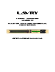
LavryBlue Series Model LE•4496 Modular Audio System Operations Manual Lavry Engineering, Inc. PO Box 4602 Rolling Bay, WA 98061 (360) 598-9757 http://lavryengineering.com/ e-mail: [email protected] Revision 2.0C April 2007 LavryBlue Operations Manual Table of Contents Page 1) LavryBlue 4496 System Overview 3 2) M•SYNC Multi-channel Sync Module a) Overview 4 b) Operation 5 c) Specifications 6 3) M•AD-824 Analog to Digital Converter a) Operation 7 b) Settings 10 c) Specifications 12 3.) M•DA-824 Digital to Analog Converter a) Operation 13 b) Settings 15 c) Specifications 16 4.) MicPre Microphone Preamplifier a) Operation 17 b) Settings 18 c) Specifications 18 5.) Opening the 4496 19 6.) 4496 Chassis Specifications 19 7.) Warranty 20 2 LavryBlue Operations Manual LavryBlue 4496 System Overview The LavryBlue System is a modular 1U high 19 inch rack unit, configurable to accommodate multiple functions including Digital to Analog conversion, Analog to Digital conversion, and Microphone Preamplification. The hardware is designed to operate at industry standard 44.1, 48, 88.2 and 96 kHz sampling rates, with the additional flexibility in “Wide Mode” of operation from external clocks at non-standard or variable sample rates in the ranges of 42 to 50 kHz and 84 to 100 kHz. The Lavry Blue chassis contains a power supply equipped with additional output power noise filtering. The modules are bolted in and connected to each other in a daisy chain manner, enabling power distribution across the chassis. This interconnection also provides for communication between the units that in some cases are user selectable. One of the advantages of this approach is the ability for AD converters to “share” a common clock source- the M·SYNC- to minimize jitter and operate multiple channels in phase. The chassis provides room for up to 4 “single width” modules. Most modules are single width 2-channel units, so the chassis has space for up to eight channels of conversion or processing. The MicPre is also 2channel, but it takes up the space of two AD or DA modules, so one chassis can provide up to four channels of microphone preamplification. Each module has a front panel and a rear panel that are directly in-line with each other from front-to-back in the 4496 chassis. This flexible design means that the Lavry Blue chassis can be configured to accommodate anything from a single module for stereo AD or DA conversion, to a maximum of eight channels of conversion. The unit may be configured for any mix of functions- for example: 2 channels of AD and 2 channels of DA, or 6 channels of AD plus 2 channels of DA. One popular configuration is 2-channels AD, 2-channels of DA and 2-channels of MicPre. Another advantage is that the LavryBlue can initially be purchased in a “minimal” configuration and then later upgraded to add more channels or different functions, as the user’s needs change. Please see “Opening the LavryBlue 4496” on page 20 for details. All modules are added left-to-right. Because the M•SYNC provides the clock source for all A-to-D conversion, the M•AD-824 A-to-D modules must be grouped together on the left side of the 4496 chassis. M•DA-824 D-to-A converters are placed in the next available slots to the right of the A-to-D’s. The MicPre would be furthest to the right in 4496 units with converter modules. The MicPre is a doublewide module, and thus would occupy two “slots.” Another aspect of the modular approach is that all analog audio and AES/SPDIF digital connections are made externally. The only interconnecting signals internal to the 4496 are detailed below under “Shared clocks and settings.” For example, this means that if you wanted to record the MicPre output using the M•AD-824, you would need to connect XLR cables from the MicPre output to the M•AD-824 input. Or, if you wanted to monitor the M•AD-824’s digital output through the M•DA-824, you would need to provide an AES digital connection to the M•DA-824 from the M•AD-824 or the device the M•AD-824 is feeding. Shared AD clocks and settings: Operating multiple channels of Analog to Digital conversion with independent clocks can creates timing or “phase-shift” differences that degrade sonic imaging. To avoid this problem, a Master Sync unit (the “M•SYNC”) controls the clocks of all AD converters in the 4496 simultaneously. It takes the form of an additional printed circuit board that is controlled by the panel on the left side of a LavryBlue equipped with AD converters. In multichannel systems, user settings such as word length or dither are typically the same across all channels, so a selectable “Master-Slave” mode is available on the M•AD-824 module. This allows the front panel parameters set on the Master module to be sent to the Slave modules so that each module does not need to be set individually. Stand alone DA modes: The M•DA-824 digital to analog converter functions well as a stand-alone unit. CrystalLock jitter elimination enables the M•DA-824 to clock externally while virtually eliminating the audible effects of source jitter. Independent operation also means multiple signals at different sample rates can be converted asynchronously from digital to analog in the same 4496 unit equipped with multiple DA modules. Although the DA’s operate independently, the CrystalLock™ and Narrow modes have a fixed “propagation delay,” so the outputs from multiple DA’s clocked from a common source remain coherent. 3 LavryBlue Operations Manual M●SYNC Multi-Channel Sync Module 1.) M•SYNC OVERVIEW The M•SYNC supplies the clock signal for all M•AD-824’s in a 4496 frame. It is controlled by the leftmost panel on the front of the 4496. If there are no M•AD-824’s in your 4496, there will not be an M•SYNC. In this case, a LAVRY ENGINEERING logo panel takes the place of the M•SYNC panel. For A-to D Clocking Modes, there are three options: -For Internal Clock operation set the far right switch on the M•SYNC to INT. There are different types of “jitter” that can affect digital systems; some become part of the recording and others don’t. Jitter in the A-to-D converter’s master clock can cause inaccuracies that DO become part of the recording. Jitter in transmission from the converter to the device it is feeding (a recording PC for example) DOES NOT become part of the recording. Therefore, Lavry Engineering recommends that you operate A-to-D converters on “Internal Clock” if possible. -For External Clock operation, set the far right switch on the M•SYNC to one of two external sync modes: WRD CLK to lock the M•SYNC to an incoming external word clock signal. The lock condition is indicated when the lock lamp illuminates. AES to lock the M•SYNC to an incoming external AES Sync signal. The lock condition is indicated when the lock lamp illuminates. -The SYNC IN BNC connector is for feeding WORD CLOCK and AES SYNC signals to the M•SYNC. -The SYNC OUT BNC connector is for supplying WORD CLOCK from the M•SYNC to external devices. -There is a 2X SWITCH on the M•SYNC rear panel near the BNC connectors. Select “ON” to enable the unit to receive standard sync rates (42-50 kHz) while facilitating conversion at double speed (84-100 kHz). See External Clock Operation (below) for details. -PLEASE NOTE: The M•SYNC is NOT internally terminated. See “Regarding Termination” under the M•SYNC Specifications section (Page 6). 4 LavryBlue Operations Manual 2.) M•SYNC OPERATION INTERNAL CLOCK OPERATION: Set the right-hand switch on LavryBlue M•SYNC to “INT.” The Narrow/Wide switch has no effect when the M•SYNC is set to “Internal” operation. The “Lock" lamp does not illuminate during Internal Clock operation. The 2 left switches set the sample frequency for Internal Clock and External Clock Narrow Mode. The HIGH/LOW switch is set to High for 88.2 and 96 kHz, and to Low for 44.1 and 48 kHz. SAMPLE RATE SWITCH POSITIONS: Sample Rate-indicated by LED 44.1 kHz 48 kHz 88.2 kHz 96 kHz 48/96 - 44/88 Switch Down Up Down Up High – Low Switch Down Down Up Up EXTERNAL CLOCK OPERATION: Set the right-hand switch to “WRD CLK” or “AES.” The unit locks to a signal applied to the rear panel BNC connector labeled “SYNC IN.” -WRD CLK locks the M•SYNC to incoming word clock. When lock is achieved, it is indicated by the LOCK lamp illuminating. -AES locks the M•SYNC to an incoming AES signal. When lock is achieved, it is indicated by the LOCK lamp illuminating. The use of “AES BLACK” for AES Sync is recommended, whenever possible. This is an AES signal with all of the audio data set to “0” or in other words “Mute.” Setting the WIDE/NARROW switch to NARROW provides a +/- 150 PPM lock range. Use this setting for standard sample rates: 44.1, 48, 88.2, & 96 kHz. In Narrow mode, the incoming Sync signal’s sample rate MUST MATCH the settings of the M•SYNC to “Lock” (see Sample Rate Switch Positions- above, and 2X Switch- below). Setting the WIDE/NARROW switch to WIDE and the HIGH/LOW switch to LOW provides external clock operation in the 42-50 kHz range. Setting the WIDE/NARROW switch to WIDE, and the HIGH/LOW switch to HIGH provides external clock operation in the 84-100 kHz range. The rear panel 2X switch must be “OFF” for this configuration. -When in NARROW lock, one frequency indicator lamp shows the selected output rate. -When in WIDE lock and LOW, the top lamps (44.1 and 48 kHz) are lit simultaneously to indicate 42-50 kHz range. -When in WIDE lock and HIGH, the bottom lamps (88.2 and 96KHz) are lit simultaneously to indicate 84-100 kHz range. 5 LavryBlue Operations Manual (External Clock Operation-cont.) -There is a 2X SWITCH on the rear panel near the BNC connectors. Set the 2X SWITCH to “ON” and the M•SYNC’s HIGH/LOW switch to “HIGH” to enable the unit to receive standard sync rates while facilitating conversion at double speed. This feature allows high-speed sampling in facilities without highspeed sync capability. “2X” mode works in both narrow and wide lock. In NARROW mode this means sync signals of 44.1 or 48 kHz would allow AD operation at 88.2 or 96 kHz respectively. In WIDE mode this means a sync signal in the range of 42-50 kHz will allow conversion at twice the frequency (84-100 kHz). The front panel lamps indicate the AES output sample rate. The 2X SWITCH “OFF” position requires the frequency of the external sync signal and M•SYNC sample rate switch settings to match in Narrow Mode. FOR EXAMPLE: if you have 48kHz external word clock source, the M•SYNC module can generate a signal at 96kHz to clock the A-to-D converter(s) when the 2X Switch is “ON,” and the M•SYNC’s switches are set to “48/96,” “High,” “Narrow,” and “Wrd Clk.” 3.) M•SYNC SPECIFICATIONS INTERNAL CLOCK ACCURACY+/- 25 ppm (parts per million) NARROW MODE LOCK RANGE: +/- 150 PPM for standard sample rates: 44.1, 48, 88.2, & 96 kHz. WIDE MODE LOCK RANGE: 42-50 kHz range in “LOW” 84-100 kHz range in “HIGH” SYNC INPUT: The unit accepts an input sync signal at the rear panel BNC labeled “SYNC IN.” This can be either a standard: Sample rate WORD CLOCK “5V TTL level” (2.5V-5V amplitude) or an AES SYNC SIGNAL (2.5V-5V amplitude). The input IS NOT internally terminated- please see “Regarding Termination” (below). SYNC OUTPUT: The unit provides an output sync signal at the rear panel BNC labeled “SYNC OUT.” The signal is useful for driving another LavryBlue 4496 system (for example a multi-channel application requiring more than 8 channels of A-to-D). The output clock is a 75-ohm back terminated 3V signal (compatible with the BNC input of the next 4496 chassis and standard WORD CLOCK inputs). REGARDING TERMINATION: If the 4496 is the only unit being fed the Word Clock signal, connect the cable using a BNC "T" adapter plugged into the “Sync In.” On the other side of the “T”, place a 75 Ohm BNC terminator connector. If the Word Clock is “chained” using “T” connectors to other devices, be sure that there is a 75 Ohm terminator on the “T” of the LAST device in the chain, and that none of the other devices have INTERNAL TERMINATION. Alternately, if there is only ONE device with internal termination, it can be wired at the “end of the chain” in place of the terminator. The important point is that there is only ONE termination and it is located at the end of the chain. 6 LavryBlue Operations Manual M•AD-824 Analog to Digital Converter M●AD-824 OPERATION The M•AD-824 is a two-channel unit, converting analog audio to AES digital output in wordlengths of 16, 20, or 24 bits. It receives its clock (internal or external) from the M•SYNC board (multi channel sync). All M•AD-824 units in a 4496 frame receive the same clock signal from the M•SYNC to minimize jitter and inter-channel timing differences. Looking at the back of the 4496, each M•AD-824 module has a group of three XLR connectors. In each group, the LEFT INPUT is the right female XLR and the RIGHT INPUT is the left female XLR connector. The male XLR is the AES digital output. This “mirror image” position of the analog inputs is due to the straight-through construction of the modules. Facing the front of the 4496, the Left channel is on the LEFT and the Right channel is on the RIGHT side of each module’s PC board. The analog inputs are electronically balanced +4dBu nominal level, configured by internal DIP switch for Pin 2 “+” (non-inverting) operation. The output of the M•AD-824 is AES digital format, which is a 110 ohm balanced 5V standard. The output is compatible with SPDIF format (75 ohm unbalanced), and can be made compatible by using a simple adapter cable or “barrel” adapter from RCA to XLR. In some cases with older SPDIF I/O, it may be necessary to use a transformer or simple electronic “level shifting” interface designed for this purpose, but this is not typically the case. Because the M•AD-824’s AES output is transformer coupled, the signal conductors MUST connect to pin 2 and pin 3 of the XLR connector. It is also OK to connect either Pin 3 or Pin 2 to Pin 1 (but not both) in the XLR connector that plugs into the AES output. Interface Standard/ Connector type AES XLR SPDIF RCA Signal + Pin 2* Center Pin Signal Pin 3* Outer Contact Shield Pin 1 Outer Contact *Please Note: Because the AES/SPDIF signal is “polarity independent,” Pin 2 and Pin 3 can be interchanged in the wiring scheme. All analog audio and digital audio connections to the M•AD-824 are made with the three XLR connecters on the back panel. There are no connections internal to the 4496 for these signals. 7 LavryBlue Operations Manual 1.) USING THE “SET/SELECT” SWITCH ON THE M●AD-824 The SET/SELECT switch is intuitive and actually far easier to use than to describe! Use it to enter (or exit) the Program Mode by holding the switch either up or down for 3 seconds. There are individual functions (Saturation Modes, Reference, & Peak Hold) and multiple parameter functions (Wordlength, & Dither/ABC). SELECT- click switch “Down” to moves the indicator from one function to the next. In all cases, toggling the switch “Down” enables the indicated parameter as the next function is selected. SET-click switch “Up” to toggle individual functions “On” and “Off”. For individual functions, a constantly illuminated lamp means “On” and blinking lamp means “Off.” For multiple parameters, SET moves the indicator sequentially through each parameter. In multiple parameters possible choices are indicated by a blinking lamp, and the current selection is indicated by a constantly illuminated lamp. To move through all functions, continue toggling SELECT. The lamps for the parameters or function will illuminate to indicate their status as you toggle through each function, then move on to the next function. To exit the program mode, hold the switch either UP or DOWN for 3 seconds. If you don’t use the switch for 10 seconds, the unit will automatically exit the program mode, except in Reference Mode, which will remain active until you toggle down (SELECT). All settings are retained in a non-volatile memory; thus, turning the power on will restore the last set of parameters programmed by the user 2.) SELECTING THE DESIRED WORD LENGTH (16, 20, 24 bit). Enter program mode and the Word Length lamps illuminate (the first group of parameters in the list). To set the Word Length, Toggle up (SET) until the lamp next to the desired word length of 16, 20, or 24 bits stops blinking. Remember: while in “SELECT MODE,” if the lamp is blinking the function is not selected or “OFF”. If it stays lit, it is selected or “ON.” The indicated Word Length can now be enabled by toggling down (SELECT). By “Selecting,” the status of the next function is also displayed3.) Analog Soft Saturation This is an analog peak limiter before the input of the A-to- D converter to protect against overloads. An internal 3-position jumper, J6, enables the threshold to be lowered or raised for the analog soft saturation feature. Please refer to the “Settings” section (below) for details. Default setting is a –3dBFS threshold. 4.) Digital Soft Saturation Select this option to emulate an overdrive condition of magnetic tape. Signal levels below -12 dBFS digital are raised 6db’s. Above this level, a transfer function that emulates analog tape saturation is applied to the waveform. As a result signal peaks that would have reached “0dBFS”are reduced by 6dB’s. Please keep in mind that enabling this mode automatically adds 6dB more level as seen on the meters of the M•AD-824 (for signals below the –12dBFS “threshold”), so the point at which the “saturation” starts is “-6dB” on the meters. The MAX lights still indicate when the maximum input level of the converter is exceeded and the resulting digital waveform will be “clipped.” Please Note- If your music source has a fairly high average level, and the input is already high enough that the signal peaks are near “0dB” on the meters, you may find that you want to lower your input level when you switch this function “ON.” This may mean that the increase in level is less than the maximum 6dB’s possible, but at that point (with that much “saturation”) it will probably sound noticeably distorted. This function is not supposed to replace a limiter, if that is what is called for. The design is optimized to prevent an occasion loud peak from causing clipping if the level was raised in a program source that has a relatively low average level with occasional peaks that are much louder- a “wide dynamic range.” The next two functions in Program Mode are METER functions; they will be addressed later. 8 LavryBlue Operations Manual 5.) SELECT DITHER & OPTIONAL NOISE SHAPING for 16bit or 20 bit modes. Dither, ABC-1 and ABC-2 are grouped together (similar to Word Length). • Acoustic Bit Correction® is dither plus psycho-acoustic enhancement of the converter’s dynamic range for word length reduction to 20 or 16 bits. (Some describe this as getting more than 16 bits performance with a 16 bit word length.) • ABC-1 provides a gentler enhancement curve. • ABC-2 provides a more aggressive enhancement curve. • NOTE: Setting the position of the internal DIP switch position to “ON” changes ABC-1 and ABC-2 to less aggressive curves. Please refer to the SETTINGS SECTION on pages 10-11. 6.) METER FUNCTIONS The meters on the M•DA-824 display the “digital level”- or in other words the peak level of the signal after it has been encoded by the A-to-D converter. This means they are extremely accurate, and will reflect adjustments made to the analog input trimmers. This also means that there is no way to show actual signal level above “0 dB” or “Full Scale Digital” (all bits “On”). The MAX lamps indicate that this level has been exceeded, but not by how much. This is why the lamps from –5 dB to 0 dB are red- to indicate that with typical audio signals you are approaching the level where a loud peak might be “clipped” by exceeding 0 dB. It is desirable to record as loud as possible without exceeding 0 dB and thus making the MAX lamps light. So don’t be afraid to “record in the red” of the M•DA-824’s meters, but it is best to avoid lighting the MAX lamps. See “Saturation Modes” (sections 3&4 above) for ways to record higher levels without “clipping.” 7.) PEAK-HOLD- Enabling this function will indicate and “hold” the highest peak level. The peak that is held can be reset by quickly activating the front panel switch. 8.) REFERENCE METER BRIDGEIn this mode, the range of the M•AD-824’s meters are “expanded” around the reference level so that each lamp indicates approximately 0.2dB of input level change above or below the reference level. To use this mode you need an analog audio reference tone source (1 kHz for example). The tone needs to be at a level that corresponds to the AVERAGE level of the music source. This “average” level will typically be in the range of 10 to 20dB’s below analog PEAK level of the music program. For those with VU meters, this would typically be “0dBVU.” For those without VU meters, that have a PC interface with fixed “+4” level outputs, the equivalent would be a digital tone at a level 14dB below 0dBFS routed to a pair of analog outputs that are feeding the M•AD-824’s analog inputs. (The digital level “0dBFS” is sometimes referred to as digital “clipping” level) Before applying the tone, use the “Select/Set” switch to select “Reference.” An illuminated pair of lamps (Left and Right channel) indicates the reference level between -10 and -20dB on the meters- they will be near the middle of the meters’ range. Toggle “SET” to move these lamps to the desired reference level (-10, -12, -14, -16, -18 or –20dBFS as indicated by the scale printed on the meter of the M•AD-824). Apply the tone to the analog inputs of the M•AD-824. If the top lamps of the meter are lit, it means that the analog input level is ABOVE the meter range, and if the bottom lamps are lit the level of the tone is BELOW the range. Use a small screwdriver to adjust the front panel 20-turn pots to bring the input level “on scale” and the lamps will appear to move up from the bottom or down from the top until they coincide with the selected reference level. This indicates that you analog reference level (“0dBVU” for example) corresponds to the digital reference level of the M•AD-824. You can also set the level above or below the reference mark for reference levels between the available marks (for example, five lamps below “–10 reference level” would be “-11dB”). Remember each lamp is ~0.2 dB’s of level change in reference mode. 9 LavryBlue Operations Manual 9.) MASTER-SLAVE MODES A module may operate in either master or slave mode. The slaves copy parameters set on the master to their immediate left. A Master module is located in the leftmost chassis position and set to “master” via its internal DIP switch (position 1 set to “ON”). All the other modules can be set to “slave” (using each one’s DIP switch- position 1 set to “OFF”). Slave module parameters may be programmed independently via the slave module’s own front panel switch. However, the master-slave relationship will override such settings; the next time the master module parameters are programmed, the settings will change immediately on all the slaves as well. So if you want to program different settings on Slave modules, be sure to program the MASTER FIRST. When the frame is powered “ON,” the slaves will always emulate the nearest master module. ●When the power is turned on, the -9dB lamps will remain steady on slave modules. The -9dB lamps will flash for a few seconds on any master modules. See the “Settings” section (below) for DIP switch location. M•AD-824 SETTINGS EXTERNAL SETTINGS on M•AD-824 front panel: Wordlength selection between 24, 20 and 16 bits Analog soft saturation, “rounding off signal peaks” to enable driving the ADC harder for extra hot recording Digital soft saturation, emulates tape saturation – enabling 6dB hotter operation for signals under 12dBFS Reference Meter Bridge with –10, -12, -14, -16, -18 and –20dBFS reference points Peak-Hold, to hold and indicate the highest peak indicated by the meters. It is reset when quickly operating the front panel switch Dither, for proper truncation to 20 or 16 bit word length. ABC-1 and ABC-2, similar to dither, but with added noise-shaping processing. The various parameters are retained in a non-volatile memory; thus, turning the power on will restore the last set of parameters programmed by the user INTERNAL SETTINGS: The M•AD-824 has a number of internal settings, which can be accessed by removing the top cover (please see “Opening the LavryBlue” Page 20). There is a “DIP switch” located on the M•AD-824 PC board that controls a number of parameters. There is also a “jumper” which can be used to set the threshold for Analog Saturation mode. The polarity of the XLR inputs on the M•AD-824 is configured at the factory for: Pin 2 “+” (non-inverting) & Pin 3 “-” (inverting) It is possible to switch the polarity to Pin 2 “-” & Pin 3 “+” by changing the setting of the DIP switch Position 2 from “OFF” to “ON.” 10 LavryBlue Operations Manual ( M•AD-824 Internal Settings- cont.) DIP switch settings: Position 1: Position 2: Position 3: Position 4: On – Master On – XLR Pin 3 “+” On – gentle ABC future enhancements Off - Slave Off- XLR Pin 2 “+” Off – aggressive ABC ● Please Note: “XLR Pin “+” refers to the “non-inverting” input. The opposite signal pin would be the “inverting input” for balanced operation. For example Pin 2 “+” would mean Pin 3 was “-” or “inverting.” Jumpers Settings: Balanced Audio Input Configuration: ● Please Note: In order to maintain good noise rejection qualities, Lavry Engineering recommends that you use balanced inputs for unbalanced sources as well. Four jumpers (J1, J2, J3 and J4) are located behind the analog input XLR connectors: Please be sure to leave the jumpers set for balanced operation. The settings are: J1 to “IN-P3,” J2 to “IN-P2,” J3 to “IN-P3,” and J4 to “IN-P2” Soft Saturation: Jumper- J6 enables the lowering of the threshold for the analog soft saturation feature, and is labeled to denote the THRESHOLD. The default mode is a connection between the center pin and the front pin- HIGH position. A more aggressive saturation curve occurs when lowering the saturation threshold by connecting the center pin to the rear pin- LOW position). Default setting- High threshold saturation starts at –3dBFS, J6 jumper set to LOW threshold saturation starts at –6dBFS. 11 LavryBlue Operations Manual M•AD-824 Specifications Dynamic Range (22Hz – 22KHz unweighted) -114dBFS +/- 1dBFS THD+N (1KHz unweighted), Internal clock or NARROW lock, typical and worst case: -1dBFS -98dBFS typical. -96dBFS worst case. -3dBFS -102dBFS typical, -98dBFS worst case. -10dBFS -109dBFS typical, -107dBFS worst case. -20dBFS -112dBFS typical, -110dBFS worst case. Common mode rejection Greater then 100dBFS for AC power line frequencies (measured by applying 24dBu 100Hz common mode input signal, with no internal gain) Analog input levels (balanced or unbalanced source) 24dBu peak level with no internal gain (front panel pots counter clockwise) 13dBu peak level with maximum internal gain (front panel pots clockwise) Analog input Gain 11dB’s available internal gain. Gain increases when turning Front Panel pots clockwise. Analog inputs Female XLR Electronically balanced +4dBu nominal level, Input impedance 5k Ohms, configured for XLR Pin 2 “+” factory default (user selectable by internal DIP switch). Digital Output Male XLR AES Digital interface- transformer coupled, SPDIF compatible with appropriate adapters. Output Word length 24, 20 or 16 bits selectable from the front panel. Bar Graph display 21 lamps indication (color coded) for each channel, including MAX lamp (for digital overload), 0 to – 10dBFS in 1 dB increments, -12 to –20dBFS in 2dB increments, followed by –25, -30, -40 and –50dBFS to indicate low level activity. Reference Meter Bridge Enables selection of reference points (indication lamps) on the bar graph display, to –10, -12, -14, -16, -18 or –20dBFS levels. The magnified input signal is indicated in reference to the selected reference level in 0.2 dB steps. Dither Enables distortion and noise floor modulation free truncation to 20 or 16 bits word length. Acoustic Bit Correction™ Dither plus psychoacoustic enhancement of the converter dynamic range for truncation to 20 or 16 bits. ABC-1 provides a gentler enhancement curve. ABC-2 provides an aggressive enhancement curve. Note: ABC-1 and ABC-2 may be replaced by less aggressive curves using the internal DIP switch. 12 LavryBlue Operations Manual Digital to Analog Converter M•DA-824 M●DA-824 OPERATION The M•DA-824 is a two-channel module that converts digital audio to analog audio with word-lengths of 16, 20 or 24 bits at sample rates of 44.1, 48, 88.2 or 96 kHz. The M•DA-824 always clocks to the digital audio signal feeding its XLR input*. In CrystalLock or Narrow modes, it can lock to standard sample rates (44.1, 48, 88.2 or 96 kHz). In Wide mode, the module can lock to vari-speed frequencies in the ranges of 42-100 kHz. *Please Note: This means that the settings of the M•SYNC and any signal on its “Sync In” connector have no effect on the M•DA-824. One benefit to this approach is that multiple M•DA-824’s in the same 4496 unit can operate asynchronously at different sample rates. The 4496 is configured at the factory with the audio XLR outputs of the M•DA-824 set for electronically balanced line level operation (nominal +4dBm). DO NOT CONNECT Pin 2 or Pin 3 to Pin 1 in the XLR for unbalanced operation without first setting the internal jumpers. Doing so will cause distortion; although the equipment is protected against damage from short-circuit. Please see “M•DA-824 SETTINGS” (page 16) for details on operating the M•DA-824 with Unbalanced outputs. The analog outputs are electronically balanced, and the polarity can be configured by the front panel switch for Pin 2 “+” (non-inverting) operation or Pin 3 “+” operation. The setting which matches the default setting of the M•AD-824 analog-to-digital converter is: Pin 2 “+”. All analog audio and digital audio connections to the M•DA-824 are made with the three XLR connecters on the back panel. There are no connections internal to the 4496 for these signals. 13 LavryBlue Operations Manual (M•DA-824 Operation cont.) Looking at the back of the 4496, each M•DA-824 module has a group of three XLR connectors. In each group, the LEFT OUTPUT is the right male XLR and the RIGHT OUTPUT is the left male XLR connector. The female XLR is the AES digital input. This “mirror image” position of the analog outputs is due to the straight-through construction of the modules. Facing the front of the 4496, the Left channel is on the LEFT and the Right channel is on the RIGHT side of each module’s PC board. The Digital input of the M•DA-824 is AES digital format, which is a 110 ohm balanced 5V standard. The input is compatible with SPDIF format (75 ohm unbalanced), and can be “adapted” by using a simple adapter cable or “barrel” adapter from RCA to XLR. In some cases it may be necessary to use a transformer or simple electronic “level shifting” interface designed for this propose, but this not usually necessary. Because the AES input is transformer coupled, the signal MUST connect to pin 2 and pin 3 of the XLR connector. It is also OK to connect either Pin 3 or Pin 2 to Pin 1 (but not both) in XLR connector that plugs into the AES input ONLY. DO NOT connect Pin 1 to Pin 2 or Pin 3 of the AUDIO XLR’s for unbalanced operation without setting the internal jumpers first! Please see “M•DA-824 Settings” section below (Page 16). Interface Standard/ Connector type AES XLR SPDIF RCA Signal + Pin 2* Center Pin Signal Pin 3* Outer Contact Shield Pin 1 Outer Contact *Please Note: Because the AES/SPDIF signal is “polarity independent,” Pin 2 and Pin 3 can be interchanged in the wiring scheme. FRONT PANEL SWITCHESLOCK MODEUse the front panel switch to choose the lock mode that is best suited for your source. Choose CrystalLock™ to activate specialized hardware to provide almost total jitter elimination from the incoming digital signal This proprietary circuit utilizes a temporary buffer memory and a DSP controlled instrumentation digital-to-analog converter to effectively “re-clock” the incoming data to a vastly more stable internal crystal clock. The result is extremely low distortion and transparent imaging, even if the source is especially "jittery." Choose Narrow Lock to reduce the sampling frequency input range to lock to signals within +/-100ppm (parts per million) around a fixed rate (44.1, 48, 88.2 or 96 kHz). Narrow lock operation provides improved jitter rejection over Wide Lock when operating with a known fixed frequency. Choose Wide Lock for applications requiring non-standard sample rates, including most normal varispeed operations. It allows the sampling rate to run automatically between 42-50 kHz or 84-100 kHz. The indicators for 44.1 AND 48 kHz light to indicate non-standard frequencies in the 42-50 kHz range, and the 88.2 AND 96 kHz indicators light to indicate non-standard frequencies in the 84-100 kHz range. SAMPLING RATE AND LOCK INDICATORSThe converter automatically detects the incoming sample rate and displays it via one of the 4 LED indicators marked as 44.1, 48, 88.2 or 96 kHz. The Lock LED indicates that the module is locked to a digital input when it is constantly illuminated. When the Lock indicator is flashing, it indicates that a signal is not present or an unlocked condition exists (such as no signal or a missing cable at the digital input, or a digital signal with an out-of-range sample frequency). 14 LavryBlue Operations Manual POLARITY SWITCHThis switch on the front panel, with positions marked as “Pin 2 +” and “Pin 3 +”, provides the ability to invert the signal polarity. When set to “Pin 2 +”, a increasing value (positive slope) of the digital input’s waveform causes the voltage on Pin 2 of the XLR analog output to increase, and the voltage on Pin 3 to decrease. The converse is true with the “Pin 3 +” switch setting. The setting for this switch that matches the factory configuration of the M•AD-824 Analog to Digital converter is: “PIN 2 +”. Please don’t confuse the function of the polarity switch with the Balanced or Unbalanced configuration of the Analog Outputs. It is electronically switched before the output stage, so it will not physically change the connections to the XLR pins. OUTPUT LEVEL Individual front-panel volume controls (20 turn potentiometers for each channel) provide 24dB’s of adjustment range for the analog outputs. These are located in the lower left and right corners of the front panel and are marked “L” and “R.” For balanced outputs, this means a full scale digital signal “0dBFS”can be set for analog output levels in the range from 0dBu to +24dBu, and for unbalanced operation “0dBFS”can be set for analog output levels in the range from -6dBu to +18dBu. M•DA-824 SETTINGS The M•DA-824 has a number of internal settings, which can be accessed by removing the top cover (please see “Opening the LavryBlue” Page 20). 15 LavryBlue Operations Manual For unbalanced operation, you will need to set the analog output mode by positioning the user-selectable jumpers J2, J3, J4 and J5 inside the 4496. After you open the top cover, they are located next to each analog XLR output connector near the back of the module’s PC board. Jumper positions (left or right) are viewed looking at the module’s PC board with the front of the 4496 facing towards you. There are 3 pins on each jumper block. Choose the mode for each channel by selecting which position these jumpers will be in: if "Left" - jumper the two leftmost pins, if "Right" - jumper the two rightmost pins. Analog Output Mode Balanced output (as shipped from factory) Unbalanced Output – Pin 2 active, Pin3 to ground Unbalanced Output – Pin 3 active, Pin2 to ground J2 Left Left Right J3 Left Right Left J4 Left Left Right J5 Left Right Left •PLEASE NOTE: Pin 1 of each XLR is always grounded, to provide driver-side shield ground. It is highly recommended to have only the cable shield connected to Pin 1 for proper cable shield connection. Lavry Engineering does not recommend using Pin 1 as signal return for unbalanced configuration, thus all the jumpers J2-J5 should be on the board in their proper selected position and the shield should be connected on the XLR end of the cable. Clock Modes setup: a 4 position DIP switch (designated as U18) determines the clock settings as follows. Mode description Independent operation Position 1(left most) OFF Position 2 OFF Position 3 OFF Position 4 (right most) ON M•DA-824 Specifications: Noise -110dBFS (20Hz – 22KHz unweighted) Distortions 1kHz tone at -1dBFS: .002%FS 1kHz tone at -20dBFS: .0013%FS 1kHz tone at -60dBFS: .0006%FS Sample rates 96kHz, 88.1kHz, 48kHz, 44.1kHz in CrystalLock™ or Narrow with a +/- 100ppm lock range (+/- 150ppm typical) (Front panel lamps indicate sample frequency and “Lock”) 42-100kHz Wide lock mode (varispeed) Crystal lock accuracy .1ppm / 10 sec maximum Channel separation -100dBFs at 1KHz Flatness response +/- .05dB (10Hz -20KHz) Phase linearity 2 degrees (10Hz - 22 kHz) Polarity Front panel switch selects “Pin 2 +” or “Pin 3 +” Analog Outputs Balanced XLR “+4dBu nominal level” (maximum level of 24dBu +/-. 25dB) or Unbalanced (Maximum level of 18dBu +/-. 25dB). Balanced /Unbalanced settings are configurable for Pin 2 or Pin 3 “Hot” operation via user-selectable jumpers. Individual analog output front panel volume control adjustments (20 turn potentiometers for each channel) provide 0 to +24dBu range for balanced outputs, and –6dBu to +18dBu for unbalanced operation for a digital signal of “0dBFS” (full scale digital level). Digital Input AES/EBU Balanced XLR, 110 Ohm, transformer isolated. Compatible with coaxial SPDIF using appropriate adapter. 16 LavryBlue Operations Manual MICROPHONE PREAMP OPERATIONThe LavryBlue Microphone Preamplifier is a dual channel “double width” unit. This means that a 4496 frame can hold a total of two MicPre’s or one MicPre and two other modules. One popular configuration is the “2A2D2MicPre,” which has two channels each of A-to-D, D-to-A, and microphone preamplification. Use of a digitally controlled ANALOG level control ensures the precision of gain adjustment as well as consistently low noise and distortion across a gain range of 21to 70dB’s (or 11to 60dB’s of gain when using the “Pad” switch). The transformerless input employs special circuitry for very high Common Mode Rejection with extended frequency response. Impedance matching at the input stage optimizes the response for Ribbon, Dynamic, and Condenser microphones. Phantom power is enabled only in the “Condenser” setting which is indicated by the “decimal point” illuminating on the right side of both channels’ Gain Display. Phantom power can be disabled for use with vintage condenser microphones that have their own power supply, by changing an internal jumper setting (see “settings” section, below). The output is electronically balanced XLR +4dBu nominal level. The inputs and outputs are electronically balanced, and configured for Pin 2 “+” (non-inverting) operation. There are internal jumpers to reconfigure the output for unbalanced operation (see “settings” section, below). Looking at the back of the 4496, each MicPre module has two sets of two XLR connectors- two female inputs and two male outputs. In each set, the LEFT CHANNEL is the right XLR and the RIGHT CHANNEL is the left XLR connector. This “mirror image” position of the XLR connectors is due to the straight-through construction of the modules. Facing the front of the 4496, the Left channel is on the LEFT and the Right channel is on the RIGHT side of each module’s PC board. All audio connections to the MicPre are made with the four XLR connecters on the back panel. There are no connections internal to the 4496 for these signals. As a safety feature to prevent unwanted “pops” or “thumps,” the MicPre enters Protected Mode when power is applied to the MicPre. This is indicated by the level display numerals “flashing.” In this mode, they will indicate the last level that was set before power was removed as a convenient reminder, but the actual gain will be set to “Minimum.” Each channel has its own Protected Mode. To exit Protected Mode, you simply need to adjust the gain “up” or “down.” Even a quick activation of the toggle switch will cause the display to stop flashing and set the MicPre to the indicated gain. Please Note: You should always exit Protected Mode on BOTH channels after powering the 4496 “On,” even if you are not using one or both of the MicPre channels at that time. 17 LavryBlue Operations Manual SETTINGSThe MicPre has a number of internal settings, which can be accessed by removing the top cover (please see “Opening the LavryBlue” Page 20). Configuring the output for Balanced or Unbalanced operation- the outputs can be configured for Unbalanced operation by placing the jumpers U6, U7, U8, and U9 on the appropriate pins. They are located next to the male output XLR connectors. Please note that the polarity is Pin 2 “+” on the input connectors, so configuring the outputs for Pin 3 active unbalanced operation would result in the polarity of the output signal being inverted with most microphones. Lavry Engineering would therefore recommend when configuring the output for Unbalanced operation to use the “Pin 2 active” setting, and wiring the cables that plug into the MicPre outputs accordingly. The “Left” or “Right” refer to which two of the three pins the jumper is placed, as viewed facing the front of the 4496 while looking towards the inside of the back panel. Analog Output Mode Balanced output (as shipped from factory) Unbalanced Output – Pin 2 active, Pin3 to ground Unbalanced Output – Pin 3 active, Pin2 to ground U6 Left Left Right U7 Left Right Left U8 Left Left Right U9 Left Right Left Phantom Power disabling- In the special case of vintage condenser microphone that have their own power supply, it may be desirable to disable the Phantom Power when using the “Condenser” setting on the front panel switch. There is a jumper (U101) near the middle of the PC board towards the front panel for this function. It is labeled “Phantom” and the “Off” position disables Phantom Power completely. Optimizing for longer cable lengths- near the “Phantom Power” jumper is a second jumper (U80) labeled “CMMR.” The default setting of this jumper is “On” for cables up to 200 feet long. To optimize the input for cables longer than 200 feet, the jumper can be moved to the “Off” position. The “Off” position will work in either circumstance, but using the “On” position for cables less than 200 feet in length does improve the noise rejection of the input. SPECIFICATIONSFor more information please go to: http://www.lavryengineering.com/forum_images/MicPre.pdf Distortion- Measured at 100Hz, 1kHz, 10kHz, &20kHz: Gain setting 40- 0.001% Gain setting 60- 0.005% Noise- Input referenced noise at gain settings from 40 to 70dB: Input shorted -128dB 150 Ohm source -126dB Gain- Individual stepped analog control with 21 to 70 dB’s gain in 1dB steps for each channel. Pad- Front panel switch for 10 dB “Pad” controls both channels. Inputs- Two channels of electronically balanced XLR inputs wired for Pin 2 “+” (non-inverting), Pin 3 “-” (inverting). Input impedance matching for Ribbon, Dynamic, and Condenser microphones. Front panel switch controls both channels. Absolute Maximum input +3V. Outputs- Two channels electronically balanced XLR outputs +4dBu nominal level. +24dBu Maximum Output Level. Wired for Pin 2 “+” (non-inverting), Pin 3 “-” (inverting) operation. Can be configured for unbalanced operation using internal jumpers. Phantom Power +48V- Available on the input XLR connectors, only in the “Condenser” setting. Dual regulation provides exceptional inter-channel isolation. 18 LavryBlue Operations Manual Opening the LavryBlue 4496 The modular design of the LavryBlue 4496 system allows for expansion and/or reconfiguration. There are also some user configurable settings that are available inside the unit in the form of DIP switches or jumpers. In either case, you will need to open the 4496. First, BE SURE THAT YOU UNPLUG THE AC POWER CORD FROM THE BACK OF THE 4496 FRAME! DO NOT OPEN THE UNIT WITH THE POWER CORD CONNECTED. Use a #2 Phillips screwdriver to remove the ten Phillips head recessed screws that hold the top cover in place. Once these screws are removed, you can safely remove the top cover to reveal the printed circuit boards. - Please refer to the individual module’s “Settings” section for the available switch settings and jumper options. -If an M•AD-824 module and M•SYNC are to be added to a 4496 that did not previously have them installed, Lavry Engineering is required to perform the installation. There are a number of critical calibrations that are part of this procedure. Field upgrades not performed by Lavry Engineering or an authorized Lavry Dealer may void the warranty. Your dealer can provide assistance or you can contact Lavry Tech Support: [email protected] - If you need to add or change modules, please refer to the document under SUPPORT at www.lavryengineering.com entitled “Upgrading your Lavry Blue.” If you have any questions, please contact Tech Support: techsupport@lavryengineering,com LavryBlue 4496 Chassis Specifications The 4496 Chassis is a standard 1U 19”rack unit. Input Voltage“Universal” input accepts inputs of 90-264VAC, 47-63Hz, Internally fused 2.5A Current Consumption @120VACSteady-state: Typically less than 0.5A (Varies with configuration/number of modules). Steady-state Maximum: 1A Dimensions19” wide x 11.5”deep x 1.75” high (Enclosure minus clearance for switches and connectors measures 10.5” deep) Approximate Weight~ 9 lbs (Varies with configuration/number of modules). 19 LavryBlue Operations Manual LIMITED WARRANTY Subject to the conditions set forth below, for one year after the original purchase date of the product, Lavry Engineering will repair the product free of charge in the United States in the event of a defect in materials or workmanship. Lavry Engineering may exchange new or rebuilt parts for defective parts. Please call the factory for an RMA number prior to shipment. No product will be accepted for warranty service without a pre-issued RMA number. This warranty is extended only to an original purchaser of the product from Lavry Engineering, or an authorized reseller of Lavry Engineering. Products that are purchased from unauthorized resellers do not have any warranty coverage. A valid purchase receipt or other valid proof of purchase will be required before warranty service is provided. This warranty only covers failures due to defects in materials or workmanship and does not cover damages which occur in shipment or failures resulting from accident, misuse, line power surges, mishandling, maintenance, alterations and modifications of the product, or service by an unauthorized service center or personnel. Lavry Engineering reserves the right to deny warranty service to products that have been used in rental, service bureau, or similar businesses. This limited warranty gives you specific legal rights. You may have others which vary from state/jurisdiction to state/jurisdiction. LIMITS AND EXCLUSIONS LAVRY ENGINEERING DOES NOT, BY VIRTUE OF THIS AGREEMENT, OR BY ANY COURSE OF PERFORMANCE, COURSE OF DEALING, OR USAGE OF TRADE, MAKE ANY OTHER WARRANTIES, EXPRESS OR IMPLIED, INCLUDING, WITHOUT LIMITATION, ANY WARRANTY OF MERCHANTABILITY, FITNESS FOR A PARTICULAR PURPOSE, TITLE OR NONINFRINGEMENT, AND ALL SUCH WARRANTIES ARE HEREBY EXPRESSLY DISCLAIMED. LAVRY ENGINEERING EXPRESSLY DISCLAIMS ANY IMPLIED INDEMNITIES. LAVRY ENGINEERING SHALL NOT BE LIABLE FOR ANY INDIRECT, INCIDENTAL, CONSEQUENTIAL, PUNITIVE, SPECIAL OR EXEMPLARY LOSSES OR DAMAGES, INCLUDING, WITHOUT LIMITATION, DAMAGES TO RECORDINGS, TAPES OR DISKS, DAMAGES FOR LOSS OF BUSINESS PROFITS, BUSINESS INTERRUPTION, LOSS OF BUSINESS INFORMATION, LOSS OF GOODWILL, COVER, OR OTHER PECUNIARY LOSS, ARISING OUT OF OR RELATING TO THE USE OF THE PRODUCT, OR ARISING FROM BREACH OF WARRANTY OR CONTRACT, NEGLIGENCE, OR ANY OTHER LEGAL THEORY, EVEN IF LAVRY ENGINEERING HAS BEEN ADVISED OF THE POSSIBILITY OF SUCH LOSSES OR DAMAGES. ANY DAMAGES THAT Lavry ENGINEERING IS REQUIRED TO PAY FOR ANY PURPOSE WHATSOEVER SHALL NOT EXCEED THE ORIGINAL COST PAID TO LAVRY ENGINEERING FOR THE APPLICABLE PRODUCT. BECAUSE SOME STATES/JURISDICTIONS DO NOT ALLOW THE EXCLUSION OR LIMITATION OF LIABILITY FOR CONSEQUENTIAL OR INCIDENTAL DAMAGES, THE FOREGOING LIMITATION MAY NOT APPLY TO YOU. Copyright ©2000 by Lavry Engineering, Inc. All rights reserved. “Acoustic Bit Correction” and “Lavry Engineering” are registered trademarks of Lavry Engineering, Inc. http://lavryengineering.com/ Internet: [email protected] 20