1
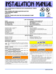
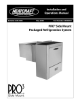
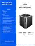
Installation and Operations
Manual
Bulletin H-IM-RACC
Replaces H-IM-73A and H-IM-43B
August 2007
Part Number 2500018
Remote Air-Cooled Condenser
Table of Contents
Inspection������������������������������������������������������������������������������ 2
Rigging and Moving Units
Installation Requirements
Unit Location
Space and Location Requirements��������������������������������������� 3
Walls or Obstructions
Units in Pits
Multiple Units
Decorative Fences
Sound Vibration
Vertical and Horizontal Condenser Assembly��������������������� 4
Typical Piping Arrangements����������������������������������������������� 5
Installation, Refrigerant Piping
Electrical Wiring��������������������������������������������������������������������� 6
Start Up���������������������������������������������������������������������������������� 8
Operation
Winter Operation Head Pressure Control
Fan Cycling Method
Fan Cycling Operation and Installation
Variable Speed
Flooded Head Pressure Control Valve���������������������������������� 9
Operation
Piping
Maintenance
Cleaning Instructions
System Warranty������������������������������������������������������������������ 11
In-Warranty Return Materials Procedure
Condenser Specifications����������������������������������������������12-13
General Fan Layout
Dimensions
Replacement Parts by InterLink™��������������������������������������� 14
Installation and Operations Manual
Inspection
Figure 2: Leg Mounting
Shipment should be checked against the bill of lading to verify
that all items listed have been received. All parts should be
carefully inspected to determine if any damage was incurred
in shipment.
Any shortage and/or claims for damage should be immediately
reported to the delivering carrier, followed by filing a claim for
shortages and/or damages.
When uncrating, care should be taken to prevent damage.
Heavy equipment should be left on its shipping base until it
has been moved to the final location.
Rigging and Moving Units
The exact method of handling and setting the unit depends
on available equipment, size of unit, final location and other
variables. It is the judgement of the riggers and movers to
determine the specific method of handling each unit.
All units are shipped on heavy skids and enclosed in open
crating. Generally, it is advisable to bring the unit as close
to its final location as possible before removing crating.
Units are provided with lifting ears near the four corners. Under
no circumstances should the coil headers or return bends be
used for moving these units.
NOTE FOR ALL MODELS: Spreader bars must be used
(contractor-supplied). Safety slings should be used when
making lift.
Figure 1: Suggested Rigging
Installation Requirements
NOTE: Installation and maintenance to be performed only
by qualified personnel who are familiar with local codes
and regulations and are experienced with this type of
equipment.
CAUTION: Sharp edges and coil surfaces are a potential
injury hazard. Avoid contact with them.
WARNING: This equipment may contain a substance that
harms public health and the environment by destroying
ozone in the upper atmosphere. Venting of certain
refrigerants to the atmosphere may be illegal in your
location. Refrigerant recovery devices should be used
when installing or servicing this product. Consult your
local codes for requirements in your location.
WARNING: Refrigerant can be harmful if it is inhaled.
Refrigerant must be used and recovered responsibly.
Failure to follow this warning may result in personal injury
or death.
Unit Location
Units are designed for outdoor application and may be
mounted on a roof or concrete slab (ground-level installation).
Concrete slabs used for unit mounting should be installed level
and be properly supported to prevent settling. A one-piece
concrete slab with footings extending below the frost line
is recommended.
Roof-mounted units should be installed level on steel channels
or an I-beam frame to support the unit above the roof. Use of
vibration pads or isolators is recommended. The roof must be
strong enough to support the weight of the unit.
© 2007 Heatcraft Refrigeration Products LLC
Part # 2500018
Remote Air-Cooled Condenser
The condenser should be located no closer than four feet from
any wall or other obstruction to provide sufficient clearance
for air entrance. Do not attach ductwork to the coil inlet or fan
outlet. Care should be taken to avoid air recirculation conditions
that can be caused by sight screening, walls, etc. Keep unit fan
discharge away from any building air intakes.
Multiple Units
Space and Location Requirements
The most important aspect in selecting a location for air-cooled
equipment is a supply of ambient air to the condenser and the
adequate removal of heated air from the condenser area. If
the requirement for adequate air circulation is not adhered to,
higher head pressures will result, creating poor operation and
possible failure of equipment. Units must not be located in the
vicinity of steam, hot air or fume exhausts.
For units placed side by side, the minimum distance between
units is the width of the largest unit. If units are placed end to
end, the minimum distance between units is four feet.
Decorative Fences
Walls or Obstructions
Fences must have 50 percent free area, with a one-foot undercut,
a minimum clearance equal to the width of the unit and must
not exceed the height of the unit. If these requirements are not
met, unit must be installed as indicated for units in pits.
The unit should be located so that air may circulate freely and
not be recirculated. For proper air flow and access, all sides of
the unit should be a minimum of the width of the unit away
from any wall or obstruction. It is preferable for this distance
be increased whenever possible.
Care should be taken to see that ample room is left for
maintenance through access doors and panels. Overhead
obstructions are not permitted. When the unit is in an area
where it is enclosed by three walls the unit must be installed
as indicated for units in a pit.
Units In Pits
Sound and Vibration
Units should be installed away from occupied spaces
to reduce the transmission of sound and vibration
to occupied spaces. Units should be mounted over
corridors, utility areas, rest rooms and other auxiliary areas
where high levels of sound are not an important factor.
Sound and structural consultants should be retained
for recommendations.
The refrigerant piping should be flexible enough to
prevent the transmission of noise and vibration from the
unit into the building. If the refrigerant lines are to be
suspended from the structure of the building, isolation
hangers should be used to prevent the transmission
of vibration.
Where piping passes through a wall, it is advisable to pack
fiberglass and sealing compound around the lines to minimize
vibration and retain flexibility in the lines. The unit needs to
be secured in its final location. Holes are provided in the base
runner for this purpose.
The top of the unit should be level with the top of the pit and
side distance increased to two times the width of the unit.
If the top of the unit is not level with the top of pit, discharge
cones or stacks must be used to raise discharge air to the top
of the pit. This is a minimum requirement.
*W = Total width of the condenser.
Remote Air-Cooled Condenser Installation and Operations Manual, August 2007 Installation and Operations Manual
Vertical Condenser
1. Remove fasteners securing condenser to skid.
Vertical airflow units should be located no closer than the width
of the unit from a wall or other obstruction. If two or more units
are to be positioned in the same area, a similar distance should
be maintained between adjacent units. Sufficient free area
should be left around and below unit to avoid air restriction
to coil.
. Remove leg extensions (Figure 4, item 1) by removing four
5/16” x 3-1/2” bolts.
Leg Assembly for Vertical Airflow Installation
(Models 008-016; 1-3)
Figure 3. Leg assembly (vertical airflow, models 008-016; 1-3)
3. Install as shown in dotted lines with same four bolts.
4. Install mounting angle (item 2) as shown (dotted lines) with
four 1/4 - 20 x 3/4” bolts provided.
5. Condenser can be hoisted by attaching hooks into 1-1/2”
holes in leg assemblies.
Horizontal Condenser
Horizontal airflow units should be installed with the coil (inlet
air side) facing the prevailing winds. Where strong winds
are common, it is recommended that a wind deflector (not
supplied) be used to discharge the air vertically from the unit,
to prevent capacity loss during varying wind conditions. The
wind deflector should be installed on the fan side of the unit.
If horizontal airflow units are installed with the air inlet facing
a wall, a distance of at least 48 inches should be maintained
between unit and wall. If it is necessary to have the unit
positioned so the air discharge is toward a wall, it should be
spaced at a distance no less than three times the coil face
height from the wall.
Leg Assembly for Horizontal Airflow Installation
(Models 008-016; 1-3)
Figure 5. Leg assembly (horizontal airflow, models 008-016 ; 1-3)
1. Assemble the unit’s two legs (Figure 3, item 2) using three
1/4 - 20 x 3/4” long bolts per leg. Captive nuts are provided
on unit for this assembly.
. Four gussets (Figure 3, item 3) are provided for
leg support.
3. Assemble the gusset in each corner with 1/4 - 20 x 3/4” long
bolts and 1/4” nuts.
4. Discard the four mounting angles (Figure 5, item 1).
Leg Assembly for Vertical Airflow Installation
(Models 024-133; 5-26)
Figure 4. Leg assembly (vertical airflow, models 024-133; 5-26)
1. Attach four mounting angles (Figure 5, item 1) to the
unit, using two 1/4 - 20 x 3/4” long bolts and 1/4” nuts per
mounting angle.
. Discard the two legs, (Figure 3, item 2) and four gussets
(Figure 3, item 3).
Part # 2500018
Remote Air-Cooled Condenser
Leg Assembly for Horizontal Airflow Installation
(Models 024-133; 5-26)
This condition can be overcome in one of two following
ways:
Figure 6. Leg assembly (horizontal airflow, models 024-133; 5-26)
1. The discharge line may be properly sized for the desired
pressure drop at full load conditions and an oil separator
installed at the bottom of the trap in the discharge line from
the compressor.
. A double riser discharge line may be used as shown
in Figure 8. Line A should be sized to carry the oil
at minimum load conditions and Line B should
be sized so that at full load conditions, both lines would have
sufficient flow velocity to carry the oil to the condenser.
Figure 8
1. Remove bolts securing condenser to skid.
. Remove item 1 and attach to rear of bottom leg (item A)
to complete mounting base. Item 2 is not required in the
horizontal discharge application and may be discarded.
3. Condenser can be hoisted by the 1-1/2” holes in
leg assemblies.
Typical Piping Arrangements
Figure 7 illustrates a typical piping arrangement with
a remote condenser located at a higher elevation, common
when the condenser is on a roof and the compressor and
receiver are on grade level or in a basement equipment
room.
Figure 7
For more complete information, please refer to the ASHRAE
Handbook on Systems.
NOTES:
1� All oil traps are to be as short in radius as possible.
Common practice is to fabricate the trap using three
90-degree ells.
2� Pressure relief valves are recommended at the condenser
to protect the coil.
3� A drain line check valve is recommended for applications
where the condenser may be at a lower temperature
than the receiver.
See Tables 1, 2, and 3 for discharge and liquid drain line size
recommendations for remote condenser selections.
Installation, Refrigerant Piping
In this case, the design of the discharge line is very critical. If
properly sized for full load conditions, the gas velocity might
be too low at reduced loads to carry oil through the discharge
line and condenser coil. Reducing the discharge line size would
increase the gas velocity sufficiently at reduced load conditions;
however, when operating at full load, the line would be greatly
undersized and create an excessive refrigerant pressure drop.
Install piping according to standard accepted refrigeration
practice. The following recommendations should be adhered
to:
1. Use only refrigeration-grade copper tubing.
. Soft solder joints are not acceptable.
3. Put dry nitrogen through lines while brazing.
4. Do not leave dehydrated piping or components open to the
atmosphere any longer than is necessary.
Remote Air-Cooled Condenser Installation and Operations Manual, August 2007 Installation and Operations Manual
Table 1. Tons of Refrigeration, Discharge
Discharge Line
Line Size
(Type L
Copper OD)
1/2
5/8
7/8
1-1/8
1-3/8
1-5/8
2-1/8
2-5/8
3-1/8
3-5/8
R-22
R-404A/R-507
R-410A
Sat. Suction Temp (°F)
Sat. Suction Temp (°F)
Sat. Suction Temp (°F)
-40
0
40
-40
0
40
-40
0
40
0.75
1.40
3.70
7.50
13.10
20.70
42.80
75.40
120.20
178.40
0.80
1.50
4.00
8.00
14.00
22.00
45.70
80.40
128.20
190.30
0.85
1.60
4.20
8.50
14.80
23.40
48.50
85.40
136.20
202.10
0.61
1.14
2.98
6.01
10.46
16.49
34.08
59.95
95.48
141.46
0.70
1.31
3.44
6.96
12.10
19.07
39.43
69.36
110.47
163.67
0.79
1.48
3.87
7.81
13.58
21.41
44.26
77.85
124.00
183.71
1.17
2.20
5.76
11.64
20.21
31.92
65.88
115.90
184.62
273.54
1.26
2.36
6.12
12.50
21.72
34.30
70.78
124.53
198.36
293.90
1.33
2.49
6.52
13.17
22.88
36.14
74.57
131.20
208.98
309.69
Source: ASHRAE Refrigeration Handbook.
1.
Line sizes based on pressure drop equivalent to 1°F per 100 equivalent feet.
2.
Values in table are based on 105°F condensing temperature. Multiply table capacities by the factors in Table 2 for other condensing temperatures.
3.
If subcooling is substantial or the line is short, a smaller line size may be used. Applications with very little subcooling or very long lines may require
larger sizes.
Table 2. Condensing Temperature Correction Factor
Temp.
90
100
110
120
130
R-22
0.88
0.95
1.04
1.10
1.18
Discharge Line
R-404A/
R-410A
R-507
0.92
0.89
0.97
0.96
1.01
1.03
1.03
1.10
1.04
1.16
Table 3. Tons of Refrigeration, Drain
Line Size
(Type L
Copper
OD)
1/2
5/8
7/8
1-1/8
1-3/8
1-5/8
2-1/8
2-5/8
3-1/8
3-5/8
4-1/8
Drain Line
Velocity 100 FPM Refrigerant
R-404A/
R-22
R-410A
R-507
2.30
1.50
2.00
3.70
2.30
3.20
7.80
4.90
6.70
13.20
8.30
11.40
20.20
12.60
17.40
28.50
17.90
24.60
49.60
31.10
42.60
76.50
48.00
66.00
109.20
68.40
94.20
147.80
92.60
127.40
192.10
120.30
165.70
Tables 1, 2 and 3 provide recommendations for discharge and liquid drain line sizes for
remote condenser selections.
Electrical Wiring
The electrical installation should be in accordance with
National Electrical Code, local codes and regulations. Proper
overcurrent protection should be provided for the fan motors.
Wiring diagrams shown are only basic and do not show
fuses, disconnect switches, etc., which must be provided in
the field.
All standard motors have internal inherent overload protectors.
Contactors can be used instead of starters requiring thermal
protectors, eliminating the problem of furnishing the proper
heating elements.
All air-cooled condensers are furnished with either singlephase or three-phase fan motors, identified by the unit data
plate. Three-phase motors must be connected to three-phase
power voltage to agree with motor and unit data plate.
The motors must be checked for proper rotation. Be sure
to check that motor voltage and control connection agree
with electric services furnished. The motors are wired into
a common junction box. Where fan cycling is furnished and
factory installed, the motors are completely wired through the
control and to the contactors.
Electrical leads from each motor terminate at the unit junction
box. Field connections must be made from these leads through
a contactor, fuse and disconnect in accordance with local, state
and national codes.
Part # 2500018
Remote Air-Cooled Condenser
Diagram 1. Typical Wiring Diagram for Models 1-3.
Diagram 2. Typical Wiring Diagram for 208-230/1/60
208-230V/1phase/60 Hz
T1 T2
TERMINAL
BOARD
FAN MOTORS
Diagram 3. Typical Wiring Diagram for 208-230/1/60 with Fan Cycling.
208-230V/1phase/60Hz
T1
T2
M3
M2
M1
Models 105-133; 21-26 Models 049-080; 10-16
Models 008-040; 1-8
Diagram 4. Typical Wiring Diagram for 208-230-460/3/60
TERMINAL
BOARD
208-230V/3 phase/60Hz
460V/3 phase/60Hz
T1 T2 T3
TERMINAL
BOARD
FCC
FAN MOTORS
FCC
M3
M2
Models 105-133; 21-26
Models 049-080; 10-16
M1
FAN MOTORS
M3
Diagram 5. Typical Wiring Diagram for 208-230-460/3/60 with Fan Cycling
M2
Models 105-133; 21-26 Models 049-080; 10-16
M1
Models 008-040; 1-8
208-230V/3 phase/60Hz
460V/3 phase/60Hz
T1 T2 T3
CONTROL CIRCUIT*
TERMINAL
BOARD
T1
CONTROL CIRCUIT: May be 24 volt, 120 volt, or 230 volt
(as specified).
T2
GND
TERMINAL
BOARD
WARNING: There may be more than one source of electrical
current in this unit. Do not service before disconnecting all
power supplies.
CONTACTOR COILS
C1
FCC
COM
NC
CONTACTORS
C2
FCC
COM
NC
C3
C3
C2
C1
THERMOSTATS OR
PRESSURE CONTROLS
FAN MOTORS
M3
Models 105-133; 21-26
M2
M1
Models 049-080; 10-16
Remote Air-Cooled Condenser Installation and Operations Manual, August 2007 Installation and Operations Manual
Start Up
Check for proper fan rotation. Air is drawn through the coil on
all units. Be sure the fans turn freely. Rotation of the motors and
blades should be in a clockwise direction looking at the unit
from the blade side. On three-phase units, it may be necessary
to reverse two of the three power leads to the unit.
NOTE: The manifold assembly is not designed to support
field piping. Any damages to the condenser due to
excessive weight, pressure or vibration will not be covered
by standard warranty.
Operation
Winter Operation Head Pressure Control
The capacity of an air-cooled condenser varies with the
difference between the entering air dry bulb temperature and
the condensing temperature of the refrigerant.
Because air temperature in some regions varies as much as
100 degrees from summer to winter, some means must be
employed to keep the condensing temperature sufficiently
high to ensure proper operation of the refrigerant expansion
valve during low ambient operation, and also allow sufficient
capacity so that excessively high condensing temperatures do
not result during high ambient conditions. The low limit of the
head pressure is dependent upon the required pressure drop
across the thermostatic expansion valve.
For normal air conditioning applications, head pressure should
be maintained above a condensing temperature corresponding
to 90°F. This corresponds to a normal lower limit of about 60°F
ambient air. Because air conditioning is not normally required
at these lower ambient temperatures, condenser head pressure
control may not always be necessary.
However, for those applications below 60°F ambient air
temperature, two methods of condenser head pressure control
are available to meet specific job requirements and engineer/
owner preference: Fan Cycling, Variable Speed and Flooded
Head Pressure Control (FHP).
Fan Cycling Method
This is an automatic winter control method and will maintain
a condensing pressure within reasonable limits by cycling fan
motors in response to outside air temperature entering the
condensing coil. When voltage other than 230/208 is supplied
to the unit, a transformer will be provided for field installation.
Electrical protection must be provided for this transformer.
Fan Cycling Operation and Installation
The fan cycling control package consists of a weather-tight
enclosure with motor starting contactor(s), as required, and
thermostat(s). The contactor coil is 24 volts, 115 volts or 240
volts as ordered. The thermostats and contactors are wired as
shown on Diagrams 3 and 5.
Factory-installed packages are mounted on the unit and have
all motor connections completed. Field wiring consists of
connecting this panel to a power supply and fused disconnect(s)
together with the control circuit to the contactor coils.
Fan cycling is suitable for outside temperatures above those
shown in Table 4. The thermostat should be field set to shut
off the fan when the condensing temperature is reduced to
approximately 90°F.
Where operation at ambients below the range shown on
Table 4 were required, FHP must be added.
Table 4. Minimum Ambient for Fan Cycling
Model
Design T.D.
30°F
25°F
20°F
15°F
2-fan units
45
55
65
70
3-fan units
30
40
50
60
Table 5 lists approximate settings for several system T.D.’s. These
settings are approximate as they do not take into account
variations in load.
Table 5. Fan Cycling Thermostat Settings
Model
Design T.D. (°F)
2-fan units
3-fan units
Thermostat Settings
T1
T2
30
55
-
25
60
-
20
65
-
30
60
45
25
65
50
20
75
55
15
75
65
NOTE: Fans closest to the headers should not be cycled
on standard temperature or pressure controls. Dramatic
temperature and pressure changes at the headers as a
result of fan action can result in possible tube failure. Fan
motors are designed for continuous duty operation. Fan
cycling controls should be adjusted to maintain a minimum
of five (5) minutes on and five (5) minutes off. Short cycling
of fans may result in a premature failure of motor and/or
fan blade.
Variable Speed
Condenser head pressure control is provided by varying the
air flow through the condenser by changing the RPM of the
condenser fan. This control package is offered in combination
with ambient fan cycling. The fan motor next to the header
end of the condenser is the variable speed fan. The remainder
Part # 2500018
Remote Air-Cooled Condenser
of the fans are constant speed and are cycled separately using
ambient sensing thermostats.
Figure 10.
Flooded Head Pressure Control Valve (FHP)
The FHP system of head pressure control is a completely
automatic control that maintains a preset condenser pressure
without need of seasonal adjustment. The control maintains
head pressure by backing liquid into the leaving side of the
condenser, decreasing the effective condenser surface and
therefore maintaining a constant head pressure upon a drop
in ambient temperature.
Several styles of flooding valves or combinations of valves
are available. Contact the valve manufacturer for specific
recommendations.
Operation:
During normal ambient operation, the valve allows liquid
refrigerant to flow through C port (see Figure 9) and R port to
the liquid receiver.
Figure 9.
The refrigerant charge required will often be about two times
the normal charge for cold weather operation. The amount of
refrigerant that must be added to a system for winter or cold
weather operation is determined by Tables 6, 7 and 8.
(see page 10)
Piping:
As on all systems, refrigerant migration must be prevented
when using FHP. If the receiver is in a warm location, a check
valve should be placed in the line between the FHP valve
and the receiver. Good piping practice suggests a trap in
the compressor discharge line and an inverted trap at the
condenser outlet. Multiple valve applications must have valves
piped in parallel.
Maintenance
Air-cooled condensers require minimum maintenance. The
unit coil will require a periodic cleaning and this can be
accomplished by a brush, vacuum cleaner, pressurized irstream
or a commercially available coil cleaning foam.
*If receiver is located in a warm ambient, a check valve
in this location may be required to prevent receiver
gas from migrating into the condenser during the
off cycle.
As the pressure drops with a drop in ambient temperature,
the valve opens to allow high pressure discharge gas to enter
B port, pass through the valve and pressurize the receiver to
provide adequate liquid flow to the expansion valve.
(see Figure 10)
This action raises the pressure on the discharge side of the
condenser, reducing flow and flooding the leaving side of the
condenser until the pressure rises to a proper level to close
B port. The liquid receiver size is important in this type of
control and must be large enough to hold the total system
charge. If the receiver is not large enough, the liquid will be
stored in the condenser causing high head pressure at normal
ambient temperatures.
All of the condenser fan motors have sealed ball bearings. The
only acceptable service to these bearings is replacement.
Cleaning Instructions
Heatcraft recommends that the finned surface of this unit
be cleaned approximately every six months; more frequent
cleaning may be required if extreme conditions cause clogging
or fouling of air passages through the finned surface.
Calgon Corporation’s CalClean 41352 (or equal) should be
acceptable for cleaning this unit. CalClean should be applied
liberally to entering air and leaving air surfaces of the finned
area in accordance with the label directions.
CAUTION: Under no circumstances should this unit be
cleaned with an acid-based cleaner.
Remote Air-Cooled Condenser Installation and Operations Manual, August 2007 Installation and Operations Manual
Table 6. FHP Charge Factor; T.D. 25 and 30 ˚F
Additional Charge Factor
Minimum
Ambient
25 T.D. °F
30 T.D. °F
+60°F
+40°F
+20°F
0°F
-20°F
0.66
0.85
0.91
0.93
0.95
0.33
0.71
0.81
0.86
0.90
Table 7. Refrigerant Charge, R-22 (lbs.)
Model
WSS
008
009
010
016
024
040
049
061
070
080
105
113
133
DVT
001
—
002
003
005
008
010
012
014
016
021
023
026
Standard
R-22 Charge
FCB
1
1.5
2
3
5
8
10
12
14
16
21
23
26
1.0
1.0
1.5
3.5
5.0
9.0
10.0
9.5
12.5
17.5
19.0
19.0
25.0
Additional Lbs. R-22 Charge for FHP at 20° T.D. °F
Minimum Ambient
at Condenser*
+50°F
+40°F
+20°F
0°F
-20°F
1.0
1.0
1.0
1.0
1.0
2.0
2.0
2.0
2.0
2.0
2.0
2.5
2.5
2.5
3.0
4.0
4.5
4.5
5.0
5.0
6.0
6.5
7.5
7.5
8.0
10.5
11.5
12.5
13.0
13.5
11.5
12.5
14.0
14.5
15.0
12.0
13.0
14.5
15.0
15.5
16.0
17.5
19.0
20.0
20.5
21.0
23.0
25.0
26.0
27.0
24.0
26.0
28.0
29.0
30.0
24.0
26.0
28.0
29.0
30.0
32.0
35.0
38.0
39.0
40.5
For R-134a, multiply charge by 1.01. For R-404A, multiply charge by 0.91. For R-410A, multiply charge by 0.93. For alternate T.D.’s, multiply by flooded charge factors
in Table 6.
Table 8. Additional lbs. R-22 Charge for FHP and Fan Cycling Combination
Model
WSS
DVT
FCB
049
061
070
080
105
113
133
010
012
014
016
021
023
026
10
12
14
16
21
23
26
40 ˚F
SST
4.5
4.5
5.5
7.3
0.0
0.0
0.0
25 T.D. °F
20 ˚F
0 ˚F
SST
SST
10.0
13.6
10.0
13.6
12.7
18.2
17.2
23.6
7.3
17.2
7.3
17.2
11.0
22.8
-20 ˚F
SST
16.3
16.3
21.8
28.2
23.6
23.6
31.8
40 ˚F
SST
8.1
8.1
10.9
13.6
4.5
4.5
5.5
20 T.D. °F
20 ˚F
0 ˚F
SST
SST
12.7
16.3
12.7
16.3
17.2
21.0
22.7
28.2
16.3
23.6
16.3
23.6
21.8
31.9
-20 ˚F
SST
18.2
18.2
23.6
31.8
30.0
30.0
40.0
40 ˚F
SST
12.7
12.7
16.3
21.8
15.5
15.5
20.0
15 T.D. °F
20 ˚F
0 ˚F
SST
SST
16.3
18.2
16.3
18.2
21.8
24.5
28.2
32.7
24.5
31.0
24.5
31.0
32.8
40.1
-20 ˚F
SST
20.0
20.0
27.3
36.4
34.5
34.5
47.3
For R-134a, multiply charge by 1.01. For R-404A, multiply charge by 0.91. For R-410A, multiply charge by 0.93. For alternate T.D.’s, multiply by flooded charge factors
in Table 6.
10 Part # 2500018
Remote Air-Cooled Condenser
System Warranty
In-Warranty Return Material Procedure
This equipment is designed to operate properly and produce
rated capacity when installed in accordance with accepted
industry standards.
Material may not be returned except by permission of
authorized factory service personnel of Heatcraft Refrigeration
Products LLC in Stone Mountain, Georgia, USA. A Return Goods
tag will be sent to be included with the returned material. Enter
the information as called for on the tag in order to expedite
handling at our factories and prompt issuance of credits. All
parts shall be returned to the factory designated on the Return
Goods tag, transportation charges prepaid.
Failure to meet the following conditions may result in voiding
of the system warranty:
1. System piping must be installed following industry
standards for good piping practices.
. Inert gas must be charged into piping during welding.
3. System must be thoroughly leak-checked and evacuated
before initial charging. High vacuum gauge capable of
reading microns is mandatory. Dial indicating pressure
gauges are not acceptable.
The return of a part does not constitute an order for replacement.
Therefore, a purchase order must be entered through your
nearest Heatcraft Refrigeration Products representative. The
order should include part number, model number and serial
number of the unit.
4. All controls and safety switch circuits properly connected
per wiring diagram.
5. Factory-installed wiring must not be changed without
written factory approval.
6. Power supply to the system must meet the following
conditions:
a.
Voltage for 208/230 motors not less than 185 volts or
more than 253 volts. For 460 motor, not less than 414
or greater than 506.
b.
All other voltages must not exceed ±10 percent of
nameplate ratings.
c.
Phase imbalance not to exceed 2 percent.
Remote Air-Cooled Condenser Installation and Operations Manual, August 2007 11
Installation and Operations Manual
General Fan Layouts
Figure 12. Model 049-080, 10-16
Figure 11. Model 008-040, 1-8
Figure 13. Model 105-133, 21-26
Condenser Specifications
Table 9. Specifications
Model
WSS
008
009
010
016
024
040
049
061
070
080
105
113
133
Dimensions
DVT
001
—002
003
005
008
010
012
014
016
021
023
026
FCB
1
1.5
2
3
5
8
10
12
14
16
21
23
26
A
—
—
—
—
40
50
70
70
90
90
130
130
130
B
—
—
—
—
30
40
60
60
80
80
120
120
120
CFM
No.
Fans
Dia.
(in.)
1
1
1
1
1
1
2
2
2
2
3
3
3
18
18
18
18
24
26
24
26
26
26
26
26
26
2,400
2,400
2,400
2,100
5,050
6,450
10,100
12,400
13,700
12,900
20,500
19,900
19,400
Connections
(ODS)
Motor Data
HP1
1/4
1/4
1/4
1/4
1/3
1/2
1/3
1/2
1/2
1/2
1/2
1/2
1/2
FLA1
2
2
2
2
3.4
3.9
6.8
7.8
7.8
7.8
11.7
11.7
11.7
HP2
—
—
—
—
1/3
1/3
1/3
1/3
1/3
1/3
1/3
1/3
1/3
FLA2
—
—
—
—
2.6/1.3
2.6/1.3
5.2/2.6
5.2/2.6
5.2/2.6
5.2/2.6
7.8/3.9
7.8/3.9
7.8/3.9
Inlet Outlet
3/8
3/8
5/8
5/8
7/8
5/8
7/8
5/8
1-1/8
7/8
1-1/8
7/8
(2)1-1/8 (2)7/8
(2)1-1/8 (2)7/8
(2)1-1/8 (2)7/8
(2)1-3/8 (2)1-1/8
(2)1-5/8 (2)1-1/8
(2)1-5/8 (2)1-1/8
(2)1-5/8 (2)1-1/8
Net Wt.
(lbs.)
96
96
96
114
180
260
450
470
510
530
550
580
625
1 Motor voltage 208-230/1/60; 1075 RPM
2 Motor voltage 208-230-460/3/60; 1140 RPM
NOTE: Model 008-010, 1-2; available in 115/1/60 voltage; model 024-133, 5-26 available in 575/3/60 voltage
Diagram 6. Dimensions for Models 008-016, 1-3
27 5/8”
2 7/16”
7/16” Diameter Hole
15 1/4”
22”
8”
9/16”
31 1/4”
2”
18”
2”
22”
37 1/2”
13/32” x 1/2” Slots
Unit legs are removable
from units installed
for horiziontal air
12 Part # 2500018
Remote Air-Cooled Condenser
Diagram 7. Dimensions for Models 024-133, 5-26 with Vertical Air Flow
43”
Optional
External
Electrical
Box
A
24 1/2”
16”
17”
8”
34”
21 1/2”
9”
B
1”
7/8” Diameter Holes
Diagram 8. Dimensions for Models 024-133, 5-26 with Horizontal Air Flow
43”
2 1/2”
37 1/2”
9”
42 1/2”
7/8” Diameter Holes
B
1”
A
Electrical junction box is located on header end of units unless optional FAN CYCLING is ordered on 230 and 460 volt. In which case, three phase units electrical box is located
on unit end opposite header end.
Remote Air-Cooled Condenser Installation and Operations Manual, August 2007 13
Installation and Operations Manual
Replacement Parts by
Commercial Refrigeration Parts
When writing to the factory for service or replacement parts, refer to the model number and serial number of the unit as stamped
on the serial plate attached to the unit. If replacement parts are required, mention the date of installation of unit and date of
failure, along with an explanation of the malfunctions and a description of the replacement parts required.
Table 10. Replacement Parts List
Model
14 Motors
WSS
DVT
FCB
Quantity
230/1/60
230/460/3/60
008
009
010
016
024
040
049
061
070
080
105
113
133
001
—
002
003
005
008
010
012
014
016
021
023
026
1
1.5
2
3
5
8
10
12
14
16
21
23
26
1
1
1
1
1
1
2
2
2
2
3
3
3
2537974
2537974
2537974
2537974
2530355
2531191
2530355
2530355
2531191
2531191
2531191
2531191
2531191
—
—
—
—
2531193
2531193
2531193
2531193
2531193
2531193
2531193
2531193
2531193
Fan
Blades
Fan
Guards
2291820
2291820
2291820
2291836
2292422
2292625
2292422
2292625
2292625
2292625
2292625
2292625
2292625
2318491
2318491
2318491
2318491
23111026
23111026
23111026
23111026
23111026
23111026
23111026
23111026
23111026
Part # 2500018
Remote Air-Cooled Condenser
Installation Checklist
Condenser
Start Up Date
Model Number
Serial Number
Electrical
Voltage
Amperage
Installer:
Name & Address
Please retain this information with the condenser.
Remote Air-Cooled Condenser Installation and Operations Manual, August 2007 15
Since product improvement is a continuing effort, we reserve the right to make changes in specifications without notice.
The name behind the brands you trust.
CLIMATE
CONTROL
H-IM-RACC-0807 | version 000
Commercial Refrigeration Parts
Heatcraft Refrigeration Products LLC • 2175 West Park Place Blvd., Stone Mountain, GA 30087
P: 770.465.5600 • F: 770.465.5990 • www.heatcraftrpd.com