1
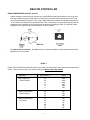
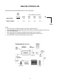
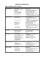
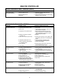
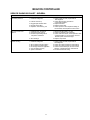
02/01
Part Number 25001501
INSTALLATION & OPERATING
INSTRUCTIONS
FOR
®
2175 West Park Place Blvd. • Stone Mountain, GA 30087 • (770) 465-5600 • Fax: (770) 465-5990
BEACON CONTROLLER
QUICK GUIDE
Installation, Start-Up, Operation, Troubleshooting
Installation
•Use 18 gauge wire for 24-volt connections between evaporators and condensing unit.
•Remove suction line sensor before brazing; reinstall suction sensor after brazing is completed and suction
line has cooled; insulate with insulation provided.
•If an electric defrost evaporator is being applied in a medium temperature application, have the nozzle size
checked for proper sizing.
Condensing Unit
•Set transformer primary connection for correct supply voltage (208V or 230V).
•Check low pressure switch time delay relay for correct adjustment to 2 minutes.
•Check low pressure switch for correct adjustment to 0 psig cut-out / 10 psig cut-in.
Evaporator
•Check black jumpers for system settings; change to match your application requirements.
•Board are shipped from factory set for 35°F medium temperature or -10°F low temperature; change resistor
for set-point temperature to match application requirements.
•Check sensor connections on board; confirm that sensors are plugged onto correct terminals.
•Check expansion valve (EXV) connections on board; confirm that wires are plugged onto correct terminals.
•If system has multiple evaporators, check master/slave wiring: Wire multi-out from master to multi-in on
slave, then from multi-out of slave to multi-in of master.
Start-Up
•After system evacuation add correct refrigerant. It may be necessary to adjust time delay relay (TDR) to 10
minutes, temporarily, to allow system charging. Readjust TDR back to 2 minutes when done.
•In ambient above 75°F, charge unit to a clear sight-glass. In colder ambients, raise discharge to 105°F
condensing and charge to a clear sight-glass.
•At initial start-up, system may cycle off on low superheat. Let system cycle. It may take 4 to 5 cycles for
system to settle out.
•If Smart Controller is used, make sure “Defrost End Temp.” on the Beacon board is set to 50°F.
•If multiple evaporators are connected to a condensing unit, the room sensor must be connected to the
master evaporator only. Disconnect the room sensor from all the other boards.
Sequence of Operation
Cooling
•The Beacon system has a built-in 4 minutes hold on / 4 minutes hold off cycle. The system will “run” in
cooling a minimum of 4 minutes and stay “off” a minimum of 4 minutes.
•When power is first applied, the system will not start for 4 minutes.
•After 4 minutes, the expansion valve opens and the compressor contactor circuit is energized shortly after
the valve opens.
•When the system is cooling, the expansion valve is adjusted at 2 minutes intervals to obtain the set
superheat. If the superheat falls too low, the expansion valve is adjusted at a much faster rate to bring the
superheat up.
•When the room temperature is obtained, the expansion valve is closed and the system is pumped down until
the low pressure switch opens or 2 minutes have elapsed.
2
BEACON CONTROLLER
QUICK GUIDE (cont’d.)
Defrost
•The actual defrost time is determined when power is first applied to the system as well as the number of
defrosts per day. If a Smart Controller is used, the actual defrost times are programmed into the Smart
Controller.
•At defrost the expansion valve closes, then the system pumps down until the low pressure switch opens or 2
minutes have elapsed. The compressor is now off.
•The fan motors are shut off and the heater contactor on the Beacon board is energized. On systems with
higher than 30 amps, the heater contactor on the board is used to energize a larger amperage contactor.
•Defrost is terminated when the evaporator coil sensor reaches the defrost termination temperature. The
heaters are turned off and the system goes through a short drain-down period.
•At the end of the drain-down period, the expansion valve opens and the compressor starts shortly after. The
fans do not run during this re-freeze period.
•At the end of the re-freeze, the fan motors start and the system is back in the cooling mode.
Trouble-Shooting
•System flashes “low pressure, high pressure, oil pressure fault”
-Check system for refrigerant leak
-Check oil level in compressor
-Check system for non-condensable
-Check low pressure switch for correct adjustment to 0 psig cut-out / 10 psig cut-in
-If ambient is below 50°F, may need to addd pressure fan cycling switch
•System flashes “superheat sensor shorted or open”
-Change evap-in and evap-out sensors
•System flashes “room temp sensor, discharge sensor, defrost termination temp sensor shorted or open”
-Change sensor as indicated
•System flashes “superheat low”
-Check evaporator coil circuits for uneven feeding; if circuits are not feeding evenly 1) check nozzle
sizing for the application, and 2) expansion valve may be defective
-Check if evap-in and evap-out sensors are plugged into correct terminals on the board
-Check if system is overcharged
•System cooling, but box temperature not met
-If a low temp evaporator is being used in medium temp application, check nozzle size
-Check if transformer is on the correct voltage tap
-Check for low refrigerant charge
-Check pump-down switch for incorrect wiring
-Check if discharge temperature is above 225°F; remove discharge line sensor from discharge line
-Disconnect evaporator coil sensor from the board
-Check value of room temperature pot setting; if value is correct, pot may be defective. Add fixed
resistor
•System “off” and will not run
-Check if room sensor is connected on the board
-Check if system has a “pump-down” switch; put switch in “normal” position
•If system has a Smart Controller
-Check to make sure room sensor is connected only to Smart Controller
-Check wiring of multi-in and multi-out to be per wiring in Installation & Operation manual
-Check program in Smart Controller; range must be on “lo” for low temp applications and “hi” for
medium temp applications
3
BEACON CONTROLLER
INSTALLATION INSTRUCTIONS
Before Installing or Starting Unit:
• Use a minimum 18 gauge wire for low voltage connections to cooler, condensing unit and Smart Controller.
• Transformer is shipped wired for 240V primary; if your supply voltage is 208V, change to the 208V tap.
• Refer to wiring schematic shipped on units for wiring; schematics in the Installation & Operation Manual are
typical schematics.
• If desired box temperature is different from preset factory temperatures (35˚F air defrost, -10˚F electric
defrost), see “Room Temperature Control”, Page 5 for options.
• Check Beacon board jumper settings to ensure that they match the application requirements; factory jumper
settings are shown on Table 3, Page 14.
• The low pressure switch time delay relay, located in the condensing unit, must be set at 2 minutes.
• Make sure all wiring connections are correct and tight.
• The suction line temperature sensor MUST be removed from the suction line before brazing the suction
tubing; the sensor MUST then be reinstalled on the suction line after brazing is completed and the tubing is
cooled.
• The Beacon timing for evaporator defrost is based on when power is first applied to the Beacon board (i.e. if
4 defrosts per day will occur at 9:00 p.m. and every 6 hours thereafter) the system will perform a defrost.
• Some systems may require the crankcase heater to be energized 24 hours prior to start-up; the Beacon
should be de-energized for this period by disconnecting the 24V lead to the condensing unit terminal block.
To start the system, this 24V lead must be re-attached.
CONDENSING UNIT
The condensing unit control panel will contain the relays, contactors, transformer and terminal block appropriately marked to match the wiring connections to be made.
UNIT COOLER(S)
Each unit cooler(s) will contain the Beacon controller, an electric expansion valve, a distributor, orifice, and
four thermistor sensors. These components are all factory mounted. The 4 sensors provide input to the
controller from the following: evap-in, evap-coil, evap-out and entering room air temperatures.
MASTER/SLAVE CONNECTION
The Beacon Controller allows multiple unit coolers to be connected in a master/slave configuration. Up to 6
Low Profile evaporators or up to 3 Medium Profile evaporators can be connected in a master/slave
configuration when using the standard factory shipped transformer. When connected in a master/slave
configuration, the entering room sensors must be disconnected from each of the slave units. When
connected to the Optional Smart Controller, the Optional Smart Controller controls the master and all the
slaves. (See Master/Slave wiring connections on typical wiring diagrams.)
During master/slave operation, there could be a delay in the reaction time of each slave to the master of up to
1 minute. The length of time is dependent on how many slaves are connected to the system.
ß
4
BEACON CONTROLLER
REFRIGERANT LINE BRAZING (CAUTION)
The electric expansion valve on the liquid line and the suction temperature sensor on the suction line are
factory installed. Care must be taken when brazing these lines at the evaporator. Too high a temperature
may destroy these components. Heat absorbing compounds or “wet rags” must be used when brazing the refrigerant line connections and the suction line sensor removed per above instructions.
WIRING
Wiring between the condensing unit and unit cooler(s) will be as follows (see attached wiring diagrams):
• High voltage - To the defrost heaters (if present) and/or fan motors. See unit cooler spec plate for ampacity.
The evaporator may also be connected to a separate power supply.
• Low voltage - 24V (18 to 30) VAC Class II control circuit. A total of 5 low voltage leads are required to
connect the condensing unit to the evaporator. Two of these leads are for connecting the compressor
discharge sensor. The other 3 leads are for connecting the compressor relay and the 24V transformer. All
24 volt wiring must be separated from the line voltage wiring.
• Compressor discharge line sensor - Use 18 gauge wire. Must be run separate from other high voltage
power wiring.
• Smart Controller (Optional) - Use 18 gauge wire. For extra long runs, 16 gauge wire may be required. Low
voltage wiring must be run separate from other high voltage power wiring.
• Slave unit(s) (if used) - Connect the multi-out terminal on the master unit to the multi-in terminal on slave
unit and the 24V (18 to 30) VAC from the master unit to the slave unit. (See wiring diagram.)
• Alarm circuit - The onboard alarm is a dry set of NC contacts which closes to indicate an alarm. Type and
wiring for the alarm is customer specified. Note that the alarm circuit does not distinguish or indicate what
has caused the alarm. (See “ALARMS”.)
Note: All wiring must comply with all applicable codes and ordinances.
ROOM TEMPERATURE CONTROL
Three methods are available:
•
Each Beacon board is shipped with a fixed resistor (attached) that controls the room temperature setpoint. Air defrost boards are set for 35˚F with a 15K ohms resistor. Electric defrost boards are set for -10˚F
with a 100K ohms resistor.
•
In the packet are additional resistors which can be used for other room temperature set-points. These
resistors are color coded. The table below shows the settings.
Resistor Color
Tape
Black
Green
White
Blue
Yellow
Red
Resistor Value
Ohms
100K
70K
30K
20K
15K
10K
Set-point
Temperature
-10˚F
0˚F
20˚F
30˚F
35˚F
40˚F
•
To change the room set-point, remove the resistor attached to the Beacon board and attach the resistor
value required for your set-point temperature. If you need a value not shipped in the packet, you may
purchase a 1/8W to 1/2W resistor from an electronics store (i.e. RadioShack), for the ohm values shown.
•
These resistors will control the room temperature at the approximate temperatures shown. These values
are also to be used for setting the Beacon board thermostat pot.
5
BEACON CONTROLLER
ROOM TEMPERATURE CONTROL (Cont’d.)
•
Another method of setting the room set-point is to use the Beacon board thermostat pot. If a value other
than that available by using a fixed resistor is required, the pot on the Beacon board can be used. First,
you must discard the fixed resistor. Then, using a digital ohmmeter, measure the resistance between the
“X” and “200K” as indicated in the illustration below. Use a screwdriver to turn the thermostat pot until the
resistance value is obtained for the desired room temperature (according to Table 1). Install the jumper
(supplied in the bag) across the terminal marked “X” when finished.
•
The Beacon Smart Controller. See Beacon Smart Controller Installation & Operating Instructions (Part
#25004101) for more details.
TABLE 1
Carbon Film Fixed Resistor selections that will control the room temperature at the approximate temperatures
shown. These values are also to be used for setting the Beacon board thermostat.
Temperature °F
*Ohms
Low Temperature
Electric Defrost
-25
-20
-15
-10
-5
0
182K
150K
120K
100K
85K
70K
Medium Temperature
Electric Defrost
20
25
30
30K
25K
20K
Medium Temperature
Air Defrost
35
40
45
50
55
60
15K
10K
8K
5K
2K
0K
Application
6
BEACON CONTROLLER
BEACON MICROPROCESSOR SETTINGS (See Table 3 for more details.)
Selections to be made by applying movable jumpers:
Defrost cycles or time - Controlled by the board in master unit only. Selection must be either “elapsed”
time or “run” time. If “elapsed” time is selected, the number of defrost must be set at either 1, 2, 4 or 6 per
day. If no selection is made, default is 4 defrosts per day. If “run” time is selected, the compressor run
time must be set at either 2, 3, 6, or 12 hours. If no selection is made, default is 3 hours compressor run
time.
Superheat - Controlled by each board in each evaporator. Selection must be either 6, 8, or 12° F. Close
coupled systems will require the higher superheat selections. If no selection is made (no movable jumper
applied) the preprogrammed default is 8° F superheat.
Defrost fail-safe - Controlled by board in master unit. Each board should have the same setting on
multi-evap systems. Must be either 10, 20, 30, 40, or 60 minutes . If no selection is made, default is 30
minutes.
Medium or low temperature - All evaporators must have the same settings for the application. For
example, on a master/slave application, all the units must have the same setting. (i.e. for medium temperature they must all be set at medium).
Test or normal - Factory set at normal. Test is also used to check board for proper function.
Type 2 or type 1 - Are not used. Do not select.
Reset time or normal - Resets all internal timers back to zero as though the unit was just powered up.
Keep jumper on normal except for momentary move to reset position. If jumper is left on RESET position,
the four minute off time will be set to zero on power up.
Forced defrost or normal - Forced defrost is used momentarily to force an extra defrost. It will not reset
the regularly scheduled defrost. Select the normal position. Note that, when initiated, the four minute.
“Hold off” and “Hold on” cycles will be in effect.
Defrost end temperature - Select either 50, 70, or 90° F. If no selection is made, preprogrammed
default is 50° F.
REFRIGERANT CHARGING
Be aware that the Beacon system does not normally require a condenser flooding valve and is capable of
operating at lower than normal condensing temperature. The condensing pressure will be raised by fan
cycling only when needed to lower evaporator superheat to the selected value.
The system does not require a winter charge. If the ambient is above 75° F, charge just until the sightglass clears. When charging in colder ambients, it will be necessary to reduce the amount of air going
through the condenser with the fans still running. Simply reduce the effective face area to raise the discharge
pressure above the equivalent 105° F. condensing temperature and then proceed to charge to clear the sightglass. Return to full condenser face area and allow the system to balance.
7
BEACON CONTROLLER
OPERATING INSTRUCTIONS
REFRIGERATION MODE
START UP
1. Check all wiring connections to be sure they are correct and tight.
2. Check voltage taps on transformer. The transformer is shipped wired for 240. If your supply voltage is 208
volt systems, charge to 208 voltage tap.
3. Check setting of time delay relay in condensing unit. It should be set at two minutes (the third marker).
4. Check the low pressure switch setting. It must be set to 0 PSIG cut out, 10 PSIG cut in, to allow start and
operation, especially in cold ambients.
5. At initial start-up, the system may cycle off at 4 minutes and display a low superheat error, then restart
itself. This cycle may be repeated a few times. Do not shut the system off. Let the system run, as it may
take a few cycles for the electric expansion valve to attain the correct setting for the desired superheat.
6. Liquid line should always be insulated.
Ambients above 50° F
At the initial application of power to the system, the compressor and the evaporator fans will be in a four
minute hold-off cycle and will not start immediately. When there is a call for cooling, the compressor starts
and the electric expansion valve (EEV) stays closed for 12 seconds. After 12 seconds, the EEV goes to
approximately half open and the compressor is put in a four minute “hold-on” cycle. (This means that the
compressor will run for a minimum of four minutes before shutting off.)
When the room thermostat setting becomes satisfied and if the compressor ran for at least four minutes, the
EEV will close and the compressor will pumpdown, then shut off. The evaporator fans will continue to run.
When the room sensor detects a rise in temperature of approximately 2°F, and the compressor has been off
for at least four minutes, the EEV opens to its last position 15 seconds before the compressor starts. Superheat adjustments at two minute intervals will then follow. During this time, the compressor will be on a
minimum four minute “hold-on” cycle. If the superheat drops to +2°F at anytime, the valve will be adjusted at
45 second intervals.
If the compressor discharge line sensor reaches 225° F for four minutes, the superheat will be lowered
temporarily, overriding the normal superheat routine to effectively keep the compressor discharge line temperature from going any higher. “Discharge high” fault will be displayed and the system will continue to
operate. A service person should check system to determine cause for high discharge temperature.
8
BEACON CONTROLLER
Ambients below 50° F and above 10° F
At the initial application of power to the system, the compressor and the evaporator fans will be in a four
minute hold-off cycle and will not start immediately. When there is a call for cooling, the compressor starts
and the electric expansion valve (EEV) stays closed for 12 seconds. After 12 seconds the EEV goes to 7/8
open and the compressor is put in a four minute “hold-on” cycle. Superheat adjustments at two minute
intervals will then follow.
When the room thermostat setting becomes satisfied and if the compressor ran for at least four minutes, the
EEV will close and the compressor will pump-down and shut off. The evaporator fans will continue to run.
When the room sensor detects a rise in temperature of approximately 2°F and the compressor has been off
for at least four minutes, the EEV will open to it’s last position, 30 seconds before the compressor is started.
Ambients below 10° F
At the initial application of power to the system, the compressor and the evaporator fans, will be in a four
minute hold-off cycle and will not start immediately. When there is a call for cooling, the compressor starts
and the electric expansion valve (EEV) stays closed for 12 seconds. After 12 seconds the EEV goes to full
open, and the compressor is put in a four minute “hold-on” cycle.
When the room thermostat setting becomes satisfied and if the compressor ran for at least four minutes, the
EEV will close and the compressor will pump-down until the low pressure switch trips or one minutes has
elapsed. The evaporator fans will continue to run.
When the room sensor detects a rise in temperature of approximately 2°F and the compressor has been off
for at least four minutes, the EEV will open to it’s last position, 30 seconds before the compressor starts.
CONDENSER FAN CYCLING
Beacon condensing units will have pressure fan cycling and ambient fan cycling as standard. On one fan
condensing units, pressure fan cycling, with a setting of 150 psig cut-out and 200 psig cut-in is used. On two
fan condensing units, one fan will be controlled by an ambient switch, set at 50°F cut-out, and the other fan
will be controlled by the pressure fan cycling switch.
9
BEACON CONTROLLER
PUMP-DOWN
At the end of each cooling cycle, when the box temperature is met, the system will pumpdown and shut off.
To pumpdown, the EEV closes and the compressor pumps down until the low pressure switch trips the unit
off, or two minutes have elapsed. While in the off cycle the system will initiate a short pump-down at four
minute intervals, if the low pressure switch is closed, to ensure that any refrigerant leakage, will not cause a
problem.
To Manually Pump-Down System
The system can be pumped down for service by closing the liquid line service valve in the condensing unit,
then closing the suction line service valve when the system trips on the low pressure switch.
or
Install a switch that will interrupt the circuit to one wire of the room sensor to the Beacon board. This will
cause the system to pump down and shut off. The system will not restart until the switch has re-made the
circuit to the room sensor.
Systems with Optional Pump-Down Switch on the Condensing Unit
The low pressure switch time delay relay will have to be adjusted from the factory set 2 minutes to 0 minutes
before flipping the pump-down switch. After normal operation of the system is restored, the low pressure switch time delay relay must be adjusted back to the 2 minute setting.
CHECKING OPERATION OF EXPANSION VALVE (EEV)
The expansion valve position is indicated by a 0 to 5 volts DC signal. At 0 Volt the valve is closed and at 5
volts the valve is fully open. At values between 0 and 5 Volt, the valve will be opened proportionately. By
using a volt meter to measure the DC volts across the pins marked “EXV TEST” (bare pins near LED) on the
Beacon board, a determination can be made if the valve is open or closed. This must be measured while the
unit is cooling.
ELECTRIC DEFROST MODE
If elapsed time has been selected (this works just like a time clock), the number of defrosts per day will
depend on the number selected on the controller (i.e. 1, 2, 4 or 6). If run time has been selected, the number
of defrosts per day will vary depending on the compressor run time (i.e. 2, 3, 6 or 12 hr.).
When a defrost is initiated, the EEV valve closes, the compressor is allowed to pump-down (see pump-down
description), the evaporator fans are cycled off and the defrost heaters are energized. The master and all
slave controllers must terminate their defrost, either on temperature or time, before the master controller will
end the defrost cycle. There is a 60 second condensate drain-down time before the compressor is started,
followed by a 60 second evaporator fan hold-off time (fan delay). After this sequence, the controller(s) are
back in the refrigerating mode and the EEV(s) open to the position prior to defrost.
AIR DEFROST MODE
Usually the cycling on the thermostat will suffice to defrost the coil(s) when operating at room temps between
35° & 45°F. However, it will be necessary to set certain parameters. Recommended values when operating
near the 35° F range are as follows: select elapsed time, 2 defrost per day, 40 min. fail-safe & 50° F defrost
end temp. When operating near the 45° F range, it is advisable to minimize the effect of the defrost by
changing to a 10 min. fail-safe & 50° F defrost end temp. Note: These are only recommended settings.
Other settings are available on the Beacon board.
10
BEACON CONTROLLER
STATUS INDICATOR
There is a red status indicator light on the Beacon board. This light has a controlled blink sequence to
indicate modes such as cooling, superheat, off, defrost, or error. (See status light blink sequence chart.)
•COOLING/SUPERHEAT: During the cooling mode, the light will blink off for two seconds, on for two seconds, off for two seconds followed by a rapid sequence of blinks that if counted will indicate superheat.
•OFF CYCLE: During the thermostat off cycle, the light will blink off for seven seconds and on for one second, which will then repeat.
•DEFROST: During defrost, the light will blink off for one second and on for one second, which will then
repeat.
ALARMS
Beacon provides a set of dry contacts that are normally closed, for use in controlling an alarm. These
contacts can be connected to a light, a buzzer or a bell., which will be activated when an alarm condition occurs.
When the Beacon is energized, the alarm contacts are OPENED. When an alarm condition is detected, the contacts are CLOSED.
Conditions under which the alarm contacts will close are:
•Power failure on or to a Beacon board.
•Room temperature of 16° F or more above thermostat set-point or 4° F below thermostat set-point, for more
than 1 hour (master controller only), when not in defrost. System will pump-down and shut off. It will restart
after four minutes.
ERROR INDICATOR & STATUS LIGHT
At initial power up, each Beacon board checks for system errors. The system error check involves checking
the various temperature sensors to determine whether any of these sensors are shorted or open.
The system will pump-down and cycle off and will not restart until the fault is cleared or the circuit breaker
reset, for the following conditions:
Superheat sensor shorted or open
Room temperature sensor shorted or jumper not installed
The system will pump-down, cycle off and try to restart, after the four minute “hold off” period, for the following
fault conditions:
Superheat too low
High pressure, oil pressure or low pressure cut-out
11
BEACON CONTROLLER
STATUS INDICATOR LIGHT BLINK SEQUENCE
Mode
Cooling
Off
Defrost
Error
Blink Time
2 sec.
1 sec.
1 sec.
8 fast
Off Time
2 sec.
7 sec.
1 sec.
2 sec.
Action
Faster blinks for superheat count, then repeat
Repeat
Repeat
Slower blinks for error code, then repeat
Error Codes
•One blink — Superheat sensor shorted or open
•Two blinks — Room temperature sensor shorted or jumper not installed
•Three blinks — Compressor discharge temperature sensor shorted
•Four blinks — High compressor discharge temperature
•Five blinks — Superheat too low
•Six blinks — High pressure, oil pressure or low pressure cut-out
•Seven blinks — Defrost Termination sensor shorted.
Note: See Table 2 for thermistor sensor resistance values at selected temperatures. To check a sensor,
place it in an ice bath (a cup with ice and water) and stir. The resistance should be 32,650 ohms at the 32° F
bath temperature.
TABLE 2
Resistance of thermistor sensors at various temperatures.
Temperature° F
104
86
77
68
59
50
41
Ohms
5,320
8,060
10,000
12,490
15,710
19,900
25,400
Temperature° F
32
23
14
5
-4
-13
-22
Ohms
32,650
42,330
55,330
72,950
97,070
130,410
176,960
EVAPORATOR FANS SHUT-DOWN BY OPERATORS
In some installations, a switch is provided which allows an operator to de-energize the evaporator fans while
loading the freezer or cooler box. This may cause the evaporator coil to freeze-up. The compressor can be
de-energized when the evaporator fan is de-energized, by wiring a 24V AC coil, double pole single throw
(DPST), relay into the fan circuit. This relay, R3, and the wiring is shown on the TYPICAL WIRING SCHEMATICS, in the back of this installation manual. For multiple evaporators, additional relays wired in parallel to
R3, to break the other fans, will be needed.
12
BEACON CONTROLLER
OPTIONAL SMART CONTROLLER
The Beacon Smart Controller performs all the standard Beacon functions with the additional benefit of remote
mounting for easy access. From the Smart Controller, the refrigeration system can be monitored and the
program parameters changed, without the user going into the Cooler or Freezer Box. The Smart Controller
allows the following:
Monitoring
•Superheat of each evaporator
•The expansion valve setting (No. of steps open or closed)
•The entering evaporator temperature
•Compressor discharge temperature
•Outdoor temperature
•Compressor run time
•Number of compressor cycles
•Maximum compressor discharge temperature
•Length of last defrost
Programming
•Box temperature
•The defrost start times - up to eight settings
•Defrost fail-safe time
•Defrost termination temperature
•Demand - Smart Defrost
•Evaporator superheat
•High and low temperature limits for alarm
•Alarm conditions time limits
•Medium temperature or low temperature system
•°F or °C
•Set the clock
•Run a quick test of the system
Other features of the Smart Controller are:
•The Smart Controller has a liquid crystal display (LCD) display which shows: current time, actual box temperature, box temperature set-point and if there is an alarm or fault condition
•Can be placed far away from the system being controlled. (500 - 1000 ft)
•Locking feature to prevent unauthorized access to program settings
•Each Smart Controller can control multiple evaporators on a system( up to 6 evaporators)
•A RS232 port is provided which allows connection to a IBM compatible computer, for monitoring the system
remotely and changing of the box temperature.
•Back-up battery will maintain the clock settings for 10 years
•Double E Prom Chip will maintain program settings indefinitely
•Large, easy to read LCD screen
•Smart Defrost - the ability to defrost only when needed
For more detailed information, see the Smart Controller Installation and Operation manual.
13
BEACON CONTROLLER
TABLE 3
The initial factory settings for the BEACON MICROPROCESSOR BOARD are indicated on the following
chart.
ELECTRIC DEFROST
FACTORY SETTINGS
AIR DEFROST
FACTORY SETTINGS
DEFROST CYCLES OR TIME
6 PER DAY/ 2 HRS
4 PER DAY/ 3 HRS
X
2 PER DAY/ 6 HRS
1 PER DAY/ 12 HRS
DEFROST CYCLES OR TIME
6 PER DAY/ 2 HRS
4 PER DAY/ 3 HRS
2 PER DAY/ 6 HRS
X
1 PER DAY/ 12 HRS
ELAPSED X
ELAPSED X
RUN TIME
SUPERHEAT
6°F
8°F
12°F
RUN TIME
SUPERHEAT
6°F
8°F
12°F
X
DEFROST FAIL-SAFE
10 MIN
20 MIN
30 MIN
X
40 MIN
60 MIN
DEFROST FAIL-SAFE
10 MIN
20 MIN
30 MIN
40 MIN
X
60 MIN
MEDIUM
X
LOW
MEDIUM
TEST
X
NORM
TEST
TYPE 2
TYPE 1
TYPE 1
X
X
LOW
X
NORM
TYPE 2
RESET TIME
X
NORM
RESET TIME
X
NORM
FORCED DEFROST
X
NORM
FORCED DEFROST
X
NORM
DEFROST END TEMP
50°F
70°F
X
90°F
DEFROST END TEMP
50°F
X
70°F
90°F
NOTE: When using the Beacon Smart Controller, the Defrost End Temperature for each Beacon board must
be set at 50° F. It is recommended that the room temperature pot for all the slave units be adjusted to the
maximum temperature 60°F when connected in a master/slave configuration.
14
BEACON CONTROLLER
PARTS LIST (Parts Dept. 800-686-7278)
HRPD PART
NUMBER
PART DESCRIPTION
Temperature Sensor
Transformer 208/240 - 24 volt - 40 VA
Transformer 208/240 - 24 volt - 75 VA (10HP + up)
Relay for condenser Fan or Crankcase Heater
Contactor for Compressor 40 amp with 24 volt Coil
Control Board for Electric Defrost
Control Board for Air Defrost
Terminal Block
Low Pressure Switch Time Delay Relay
Electric Expansion Valve
ESV 1 - 24 volt
ESV 2 - 24 volt
ESV 4 - 24 volt
uni-polar valves
ESV 6 - 24 volt
ESV-8 - 24 volt
ESV-10 - 24 volt
ESV-25- 24 volt - bi-polar valve
Expansion Valve Molded Connector
Optional Pump-Down Switch
Beacon Smart Controller
Optional Smart Controller Software Package
Bi-polar adapter board (only used with 29320001
expansion valve)
28900101
22522301
22538401
22511401
2252440
28910001
28910002
2251266
22536801
29310001
29310002
29310003
29310004
29310005
29310006
29320001
29310007
22510901
89704401
89704501
28920001
To test the Beacon board place the test jumper to the “TEST” position. The board will then cycle through each output for 10
seconds. It will energize and de-energize the fan motor, electric heater, expansion valve and compressor for 10 seconds. When
in the TEST mode the status light flashes quickly. If a sensor is bad it will flash per the error chart. AT THE END OF THE TEST
RETURN THE JUMPER TO THE NORMAL POSITION.
BEACON OPERATIONAL LIMITS
Box set point tolerance ............................ +/-2°F
Down to -20°F outdoor ambient .............. Allows start-up & operation
Below -20°F outdoor ambient ................ Requires head pressure control valve
& pressure fan cycling switch
Controlling box temp. range .................... -25°F to 60°F
Voltage range at the board ...................... 18 VAC min / 30 VAC max
Surge protection at the board .................. up to 50 VAC
15
BEACON CONTROLLER
BEACON TROUBLE-SHOOTING GUIDE
FAULT OR PROBLEM
System runs 4 minutes then cycles off, then repeats
THINGS TO CHECK
1. Check if sensors are connected correctly; if evaporator in/out
are switched, this will cause low superheat
2. Check if system is piped properly
3. System will cycle off if discharge line gets above 225°F
4. Check evaporator coil circuits if they are feeding evenly;
uneven feeding will cause flood-back
5. Check if expansion valve is correctly wired on Beacon board
6. Evap Coil temp too high; disconnect Evap Coil sensor to allow
system to run & lower temp; reconnect when temp lowered
7. Is the system wired properly between master & condensing unit
8. Check charge at 105°F; condensing sight glass should be full
9. Check fan cycling operation
System runs continuously
1. Check evaporator coil circuits if they are feeding evenly;
uneven feeding means coil is not being used fully
2. Check if red jumper wire (next to blue pot) is connected;
also check if terminals on red jumper wire are tight
3. Check if room sensor is connected
4. Check if system is properly charged with refrigerant
5. Is the system sized properly
6. Check system charge at 105°F condensing for full sight glass
System runs erratically
1. Check for low voltage condition; system will not operate
properly below 18 VAC
2. Check for high voltage condition; system will not operate
properly above 30 VAC
3. Check if expansion valve is correctly wired on Beacon board
4. Check “EVAP IN” & “EVAP OUT” sensors for proper operation
5. Is EEV wired properly
6. Is system charged properly
7. Check fan cycling operation
Sensor was changed but fault signal still appears
1. If a sensor is changed out, system power must be reset to
clear fault
System flashes low superheat fault
1. Check if “EVAP IN” & “EVAP OUT” sensors are correctly
installed on board & on copper tubing
2. Check evaporator coil circuits if they are feeding evenly;
uneven feeding will cause flood-back or sensors won’t sense
proper superheat
3. Check if system is piped correctly; incorrectly piped
system will cause system flood-back
4. Check if expansion valve is correctly wired on Beacon board
5. Expansion valve may be defective; check by running through
test mode
6. Check for proper charge at 105° condensing for full sight glass
System flashes low pressure, high pressure
or oil pressure fault
1. If outdoor temperature is below 50°F, check to make sure
time delay is set at 2 minutes
2. If pumpdown switch is installed, check to make sure it is
wired correctly in the circuit
3. Check to make sure system is charged properly with
refrigerant
4. Check if expansion valve is operating properly
5. Check if expansion valve is correctly wired on Beacon board
6. Expansion valve may be defective
7. Check for flood back to the compressor
8. Check for proper piping & oil return
9. Possible bad low pressure, high pressure or oil pressure switch
10. Possible bad time delay or mis-wired
16
BEACON CONTROLLER
BEACON TROUBLE-SHOOTING GUIDE (cont’d.)
System will not run
1. Check if red jumper wire (next to blue pot) is correctly
connected across “X” terminals
2. Check red jumper wire terminals to make sure they are
connected to the wire, not the insulation
3. Check to make sure system is correctly wired
4. Check system for low voltage or high voltage conditions;
system must have voltage between 18-30 VAC for proper
operation
5. Check if “EVAP IN” & “EVAP OUT” sensors are correctly
installed on the board & on copper tubing
6. If system has Smart Controller, check “MULTI IN” & “MULTI
OUT” connection at board & at Smart Controller to make sure
wires are not reversed
7. Check if “ROOM” sensor is connected on Beacon board
8. Check that room sensor is good by resistance check
9. Check refrigerant charge
10. If voltage is too high (above 30 volts) or too low (below
18 volts), unit will not run
Coil frost pattern is uneven
1. Check evaporator coil circuits if they are feeding properly;
uneven feeding will cause uneven icing
2. If liquid line runs through cooled space, may need to be
insulated or nozzle reselected for conditions
3. If electric defrost coil for medium temperature applications,
medium temperature nozzle must be installed
17
BEACON CONTROLLER
BEACON UNI-POLAR EXPANSION VALVE TEST VOLTAGES
ESV
TEST
VALVE OPEN
VALVE CLOSED
(Beacon Board connection)
(dc volts)
4.4
BLUE
15.6
RED
15.6
WHT
15.7
BLK
15.6
0
15.3
15.3
15.4
15.5
YEL
Com
24 Vdc
Notes:
1. All volts shown are measured while in the “TEST” mode and are DC
2. The volts shown for each step (BLUE, RED, WHT, BLK) are measured between the YEL-Com
& the corresponding pin
3. The volts shown for each step is available only when the valve is activated.
The voltage value will increase when the valve is activated, then will go to zero.
4. The “ESV TEST” volts will remain while the valve is open
18
BEACON CONTROLLER
SERVICE DIAGNOSIS CHART - BEACON
PROBLEM
POSSIBLE CAUSE
POSSIBLE CORRECTIVE ACTION
Compressor will not run
1. 4 min. off cycle
2. Box temp is below t’stat setting
3. Loose wiring
4. Bad sensor
5. Discharge temp. too high
6. Beacon board defective
7. Low pressure switch open
8. Supply voltage too low
1. Wait 4 min.
2. Lower t’stat setting
3. Check all wire terminals; tighten if necessary.
4. Check status light for problem sensor
5. Check general diagnosis chart
6. Check “Status” light; if out, replace board
7. Check pressure switch setting.
8. Change transformer primary to correct supply
voltage tap. 208 or 240 volts.
9. Temporarily disconnect “Evap Coil” sensor from
board; reconnect when coil temp is lowered
9. Evap coil temp too high
Cannot get to box temp
1. Wrong t’stat setting
2. Wrong selection on board
1. Check and adjust t’stat
2. For box temp of 20°F and above, select
“MEDIUM”; for box temp below 20°F,
select “LOW”
3. a) Increase time between defrost. b) May need
time delay across low pressure switch. (See
“Compressor cycles off at startup” below.)
4. Check if expansion valve is operating
5. Check charging procedure
6. Allow system to run longer
7. Clear ice and check defrost setting
8. Check if distributor tubes are sweating evenly; if
not, have factory check nozzle selection for
application.
9. EXV closing down due to low superheat; check
“EVAP IN” & “EVAP OUT” sensors; check
refrigerant charge.
3. Comp. run time too short
4. Bad expansion valve
5. Wrong charge
6. Box temp fluctuate
7. Evap coil iced up
8. Wrong nozzle
9. Low pressure switch
tripping compressor
Superheat light indicates
1 deg then 8 deg
1. Incorrect refrigerant charge
2. Expansion valve oversized
3. Superheat set too low
4. System not stabilized
5. Evap coil iced up
1. Check refrigerant charge
2. Check expansion valve size
3. Raise superheat setting
4. Allow system to run longer
5. Clear ice
Freezer coil icing
1. Insufficient refrigerant.
1. Check system for leaks; repair leaks &
add refrigerant
2. Raise setting on the board
3. Raise setting on the board
4. Check fan circuit and board relay
5. Check heater circuit and board relay
6. Check sensor on evap coil
2. Wrong defrost termination setting
3. Wrong defrost fail-safe setting
4. Evap fan not running
5. Defrost heater not working
6. Faulty defrost termination sensor
7. Not enough defrost for
conditions or infiltration
8. Undersized system
Compressor Cycles off at
startup w/o pumping down
1. Low pressure switch setting
too high
2. Low pressure switch
tripping compressor
3. Compressor out on thermal
overload protector
1. Change low pressure cutout to 0 PSIG
and 10 PSIG cut-in
2a.EXV closing down due to low superheat; check
“EVAP IN” & “EVAP OUT” sensors
2b.Check refrigerant charge.
2c.Check if sensors are connected to correct
terminals on Beacon board.
Unit Cycles on and off
without 4 min. time delay
1. Incorrect wiring
1a.Check wiring
1b.Bad Beacon board
2a.EXV closing down due to low superheat; check
“EVAP IN” & “EVAP OUT” sensors
2b.Check refrigerant charge.
2c.Check if sensors are connected to correct
terminals on Beacon board.
2. Low pressure switch
tripping compressor
3. Time delay bad or
not set for 2 minutes
19
BEACON CONTROLLER
SERVICE DIAGNOSIS CHART - BEACON (cont’d.)
PROBLEM
POSSIBLE CAUSE
POSSIBLE CORRECTIVE ACTION
Beacon Board Status
Light Flashes Erratically
1. Supply voltage too high
1. Check 24 volt supply; if above 30 volt
correct immediately.
2. Change transformer primary to correct supply
voltage tap. 208 or 240 volts.
2. Supply voltage too low
3. Bad board
SERVICE DIAGNOSIS CHART - GENERAL
PROBLEM
POSSIBLE CAUSE
POSSIBLE CORRECTIVE ACTION
Compressor will not run
1. Fused disconnect switch is open
2. Blown Fuse
1. Close switch
2. Check reason fuse is blown; replace fuse
after problem is corrected.
3. Motor protector is automatic reset; allow
time for compressor to cool down so that
protector will reset; check unit for reason
when compressor restarts.
4. Replace
3. Compressor motor protector open
4. Defective compressor contactor
or holding coil
5. Open room air sensor (air into coil)
6. Compressor discharge too hot
7. Open low pressure, high pressure
or oil safety control
8. Motor problems
5. Check room air sensor; if open, replace. After
reconnecting, wait 4 mins. for compressor to
restart.
6. Lower evaporator superheat to lower
compressor suction gas temperature
7. Check control settings
9. Loose wiring
8. Check motor for open circuit, short circuit,
grounded windings or burn-out
9. Check all wire terminals; tighten if necessary
Compressor noisy or
vibrating
1. Flooding of liquid refrigerant into
into crankcase
2. Compressor hold-down nuts too
tight or too loose
3. Worn compressor/bad valves
1. Check expansion valve superheat setting
on control board
2. Loosen compressor hold-down nuts until
compressor floats freely on mounting springs
3. Replace
High head pressure
1. Too much refrigerant
2. Non-condensables in the system
3. Dirty condenser coil
4. Condenser fan not running
5. Discharge valve partially closed
6. System running beyond condensing
temperatures due to heavy load
or out of equipment design paramaters
1. Remove excess refrigerant
2. Purge system of non-condensables
3. Clean condenser coil
4. Check electrical circuit, including fuses
5. Open valve
Low head pressure
1. Insufficient refrigerant
1. Check system for leaks; repair leaks &
add refrigerant
2. Replace compressor
3. Check refrigerant charge
2. Damaged valves in compressor
3. Winter operation w/o head
pressure valve
High suction pressure
1. Expansion valve over-feeding
2. High box temp. pull-down
3. System undersized
20
1. Check expansion valve superheat setting
on control board
2. Wait for box temp. to drop
3. Check load & design criteria
BEACON CONTROLLER
SERVICE DIAGNOSIS CHART - GENERAL
PROBLEM
POSSIBLE CAUSE
POSSIBLE CORRECTIVE ACTION
Low suction pressure
1. Insufficient refrigerant
1. Check system for leaks; repair leaks &
add refrigerant
2. Check defrost system operation &
correct fault condition
3. Replace filter drier
4. Replace suction filter
5. Check expansion valve superheat setting on
control board; check expansion valve screen
2. Freezer coil iced up
3. Plugged liquid line filter drier
4. Plugged suction filter
5. Expansion valve starving coil
Loss of oil or loss of oil
pressure
1. Insufficient oil in the system
2. Compressor short cycling
3. Excessive liquid refrigerant in
compressor crankcase
4. Worn bearings
Freezer coil icing
1. Insufficient refrigerant
2. Wrong defrost end temp setting
3. Wrong defrost fail-safe setting
4. Not enough defrost for application
5. Coil not feeding properly
6. System undersized
21
1. Add oil until sight-glass is 1/2 full
2. Check low pressure control settings
3. Check crankcase heater; check expansion valve
superheat setting on control board; check for
internal rupture of heat exchanger
4. Replace compressor
1. Check system for leaks; repair leaks &
add refrigerant.
2. Check unit cooler instructions. Raise setting.
3. Check unit cooler instructions. Raise setting.
4. Check for subcooled liquid, incorrect nozzle
selection, insulate liquid line, restricted coil
5. Do heat load & check sizing
BEACON CONTROLLER
22
BEACON CONTROLLER
23
BEACON CONTROLLER
24
BEACON CONTROLLER
25
BEACON CONTROLLER
26
BEACON CONTROLLER
27
BEACON CONTROLLER
28
BEACON CONTROLLER
29
BEACON CONTROLLER
30
BEACON CONTROLLER
31
BEACON CONTROLLER
32
BEACON CONTROLLER
33
BEACON CONTROLLER
34
BEACON CONTROLLER
Notes
35
Visit our web site at www.heatcraftrpd.com for Technical Literature Online.
Since product improvement is a continuing effort at Heatcraft,
we reserve the right to make changes in specifications without notice.
2175 West Park Place Blvd. •Stone Mountain, GA 30087 •(770) 465-5600 • Fax: (770) 465-5990