1
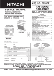
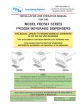
H-IM-80D
February, 2004
Part No. 25000601
Replaces H-IM-80C (12/03)
Beacon II Smart Controller
Installation & Operation
Manual
Table of Contents
Features ................................................................2-3
Installation .............................................................4
Wiring ....................................................................5
Power Supply ........................................................6
Initialization of Beacon II Smart Controller ............7
Button Functions ...................................................7
Programming Beacon II Smart Controller ............. 8
Monitoring Beacon II Smart Controller ................. 9
Locking Beacon II Smart Controller ...................... 10
Error Codes ...........................................................10
Wiring Errors .........................................................11
Alarm Codes .........................................................11
Alarm Buzzer .........................................................12
Data Logging .........................................................12
Smart Defrost ........................................................13
PC & Modem Access ............................................14
System Defaults ....................................................15
Parts List ...............................................................16
Operational Limits .................................................16
Diagnostics ............................................................17-20
Wiring Diagrams ....................................................21-23
Beacon II Smart Controller Features
The Beacon II Smart Controller performs all the standard Beacon functions with the
additional benefit of:
a) Remote mounting for easy access
b) Remote monitoring and programming
c) Controlling four completely separate systems
d) Logging data
e) Smart Defrost
f) Access via PC or modem
g) Has buzzer to signal alarms
h) Locking keypad
Beacon II Smart Controller allows complete monitoring and programming of the system.
The Controller display has the following buttons: COOLING, DEFROST, PROG REVIEW,
MONITOR, ENTER, CLEAR, SETPOINT AND TIME.
The normal LCD display will show the Programmed Box Set-point temperature. Actual Box
Temperature, the Current Time of day and the Mode (i.e. COOL, DEFROST or OFF).
When multiple systems are being controlled, the system number (i.e. SYS 1, SYS 2, SYS
3, SYS 4) will also be displayed on the LCD.
© 2004, Heatcraft Refrigeration Products LLC
2
Beacon
Controller
Features
Features II
ofSmart
the Beacon
II Smart Controller
• Monitoring of the complete refrigeration system.
• Programming of a variety of parameters for the optimum control of the refrigeration
system.
• The Beacon II Smart Controller has a Liquid Crystal Display (LCD) which shows:
current time, actual box temperature, box temperature set-point and if there is an alarm
or fault condition.
• Data Logging.
• Smart Defrost to save energy on defrost.
• Sounds a buzzer to indicate an Alarm condition.
• Can be mounted up to 1000 ft. away from the system being controlled.
• Each Beacon II Smart Controller can control four independent systems with up to 4
evaporators on each system.
• An RS232 port is provided which allows connection to system via PC or Modem.
• A Backup battery will maintain the clock settings for 10 years.
• Double E PROM Chip will maintain program settings indefinitely.
• Password protection system.
• Locking feature to prevent unauthorized access to program settings.
Box Set-point
Temperature
System
Number
Operating
Mode
Time of Day
Box
Temperature
Set-point
Slide Bar
System
Selection Bar
3
Installation
INSTALLATION
The Beacon II Smart Controller should be installed in a location where the large Liquid
Crystal Display (LCD) can be viewed easily, yet is secure and vibration free. Because of the
LCD screen, the Beacon II Smart Controller should not be mounted where it will experience
temperatures below 40°F or above 100°F.
A terminal strip for wiring connections is located on the base of the Beacon II Smart
Controller. To access this terminal strip, pull both halves of the Beacon II Smart
Controller housing apart. Mounting holes are located in the plastic base.
Beacon II Smart Controller Base
24 V Terminal
Strip
RS232
Connector
4
Wiring
WIRING
All 24 volt wiring must be run separate from the line voltage wiring.
All Low voltage wiring must be 18 gauge minimum and must be run separate from high
voltage wiring. The maximum distance from the Beacon II Smart Controller to the Master
Evaporator is 1000 ft.
The terminal strip in the Beacon II Smart Controller is labeled similarly to that of the
Beacon II boards. Connect the corresponding terminals to those on the Beacon board.
For single Refrigeration system:
Connect MULTI OUT 1 from the Beacon II Smart Controller to the MULTI IN on
the Beacon board on the Evaporator. Then connect MULTI IN 1 from the Beacon II
Smart Controller to the MULTI OUT on the Beacon board on the Evaporator. See
typical wiring diagram at the back of these instructions.
On systems with multiple evaporators the Beacon II Smart Controller must be
wired to the Master Evaporator first. DO NOT disconnect the Room sensor from any
of the Evaporators.
SINGLE SYSTEM CONNECTION
M = Master Evaporator
S = Slave Evaporator
CU = Condensing unit
For MULTIPLE independent Refrigeration systems:
For the first system, connect MULTI OUT 1 from the Beacon II Smart Controller
to the MULTI IN on the Beacon II board on the Evaporator in this first system. Then
connect MULTI IN 1 from the Beacon II Smart Controller to the MULTI OUT on
the Beacon II board on the Evaporator on this first system. DO NOT disconnect the
Room sensor from any of the Evaporators. See typical wiring diagram at the back of
these instructions.
5
Power Supply
For the second system, connect MULTI OUT 2 from the Beacon II Smart
Controller to the MULTI IN on the Beacon II board on the Evaporator in this second
system. Then connect MULTI IN 2 from the Beacon II Smart Controller to the
MULTI OUT on the Beacon II board on the Evaporator on this second system. See
typical wiring diagram at the back of these instructions.
On systems with multiple evaporators the Beacon II Smart Controller must be wired to
the Master Evaporator first. DO NOT disconnect the Room sensor from any of the
Evaporators.
DO NOT CONNECT 24V & C BETWEEN EVAPORATORS.
The Beacon II Smart Controller and the evaporators are then connected in a daisy–
chain fashion. (See the wiring diagrams in the back of this manual)
A minimum 18 gauge wire should be used. All low voltage wiring must be run separate
from high voltage wiring.
MULTIPLE SYSTEM CONNECTION
SYSTEM 1
M = Master Evaporator
SYSTEM 2
SYSTEM 3
S = Slave Evaporator
SYSTEM 4
CU = Condensing unit
POWER SUPPLY
The Beacon II Smart Controller gets it’s 24 VAC power supply from the evaporator. When
controlling multiple systems, the Beacon II Smart Controller is powered from the evaporator
of only one of the systems. If a power interruption occurs to the system supplying the
Beacon II Smart Controller, the Beacon II Smart Controller LCD screen will go blank. The
other systems will, however, continue to operate and maintain their box temperature.
The Beacon II Smart Controller can be supplied with it’s own power supply by using a 24
VAC Universal Plug-in Power Source with a minimum of 300 mA. When powered by an
independent power supply, if power is lost to the Beacon II Smart Controller the systems
6
Initialization of Beacon II Smart Controller
will continue to operate and maintain the box temperature. This occurs only if an external
power supply is used on the Beacon II Smart Controller.
If the Beacon II Smart Controller LCD displays all 88888 this indicates that the power
supply is below 18 VAC. When this occurs the system will power down and shut off. When
the power supply is corrected to 24 VAC, the system will restart after the four-minute hold
off period and resume normal operation. The Beacon II Smart Controller LCD display will
then be normal.
INITIALIZATION of BEACON II SMART CONTROLLER
When power is first applied to the Beacon II Smart Controller it checks the configuration of the
system to which it is connected and stores this in its memory. Beacon II Smart Controller
checks how many condensing units there are and how many evaporators are connected to
each condensing unit. The order in which the units are wired from the multi-out of the Beacon II
Smart Controller determines the unit ID (UNI-4) assigned by the Beacon II Smart Controller.
This is called initialization. Whenever a system is added, removed or modified (changing
the number of evaporators on a condensing unit), while connected to the Beacon II
Smart Controller, it must be re-initialized.
Place all systems in the service mode before initializing the Beacon II Smart Controller.
Make sure all wiring changes to the system and the Beacon II Smart Controller are complete
and accurate before initializing the Beacon II Smart Controller. Each SLAVE Evaporator must
also be programmed as a SLAVE BEFORE the system is initialized. The “SLA” setpoint must
be set from the board programming. It cannot be done from the Beacon II Smart Controller.
To initialize the Beacon II Smart Controller (for version 1.2),
• Press and Hold both the ENTER and CLEAR buttons until the LCD displays EEROM?
• Release the ENTER and CLEAR buttons quickly, then press the ENTER button
• The LCD will display WAIT
It may take up to 2 minutes to complete the initialization of the system after which the normal
LCD screen will appear.
BUTTON FUNCTIONS
• SYSTEM SELECTION BAR: If two or more systems are being controlled from the
Beacon II Smart Controller, this bar allows switching between systems. The display will
show the SYS number and all parameters related to that system. The cover plate of
Beacon II Smart Controller, when pushed will also change the display between systems.
• CLOCK (+ -) This is used to set the time of day on the display.
• Depress the + button to move the clock forward
• Depress the - button to move the clock backward
• When in PROG Mode, these are used to step through values for setting superheat etc.
for each evaporator of the system(s) attached to the Beacon II Smart Controller and for
different defrost start time periods.
7
Programming Beacon II Smart Controller
• COOLING: Depressing this button will start the system in the cooling cycle immediately
(The 4 minutes “Hold Off” is bypassed). This button will illuminate to indicate that the
Cooling function is “ON”. System operation will be as described under
REFRIGERATION MODE in the Beacon II installation manual.
Pressing the COOLING button while the system is cooling, and the button illuminated,
will pumpdown the system and turn it off.
• DEFROST: Depressing this button will force the system into defrost immediately (The
“Hold Off/Hold On” times are bypassed). This button will illuminate to indicate that the
Defrost function is “ON”. When in Defrost, pressing this button a second time will end
defrost.
• MONITOR: Depressing the MONITOR button will display the setpoints shown on page 10.
If one Beacon II Smart Controller is controlling two or more independent systems, you
must press the SELECTION BAR to display information on the system you want to
monitor. If multiple evaporators are connected to the system displayed, you must press
the “+” or “–” buttons to display information on the evaporator you want to monitor.
• PROG REVIEW: This button allows stepping through each of the setpoints for initial
setup and to make changes.
If one Beacon II Smart Controller is controlling two or more independent systems, you
must press the SELECTION BAR to display information on the system you want to
make program changes. If multiple evaporators are connected to the system displayed,
you must press the “+” or “–” buttons to display information on the evaporator you want
to monitor.
• CLEAR: Used to clear incorrect entries while programming or to return to the System
display when monitoring.
• TIME: Slide-bar is used to set the thermostat clock for Defrost times.
• SETPOINT: Slide-bar is used to change settings while programming.
• ENTER: To enter new settings into the program. NOTE: Settings are recorded in memory
even if power fails.
PROGRAMMING BEACON II SMART CONTROLLER
To make a change, press the PROG REVIEW button until the setpoint item that needs to
be changed is displayed. The SETPOINT Slide-bar is then used to change to the desired
new setting. When the new desired setting is displayed, press the “ENTER” button. The
new setting is now programmed into the Beacon II Smart Controller memory.
Press the PROG REVIEW button and follow the steps below (to back up one step during
programming, while pressing the “MONITOR” button, press the “PROG REVIEW”
button):
• DEFTYP – ELE or AIR: Select for Electric Defrost or Air Defrost then press “ENTER”.
This selection will automatically set the defaults for Air and Electric Defrost. Important:
This will set the refrigerant type to R22 for Air and R404A for Electric. You must change
to the refrigerant you are using in your application if these are incorrect.
• REFTYP – 22, 404, 507. Use “SETPOINT” slide-bar to display desired value, then press
“ENTER.”
• BOXTMP – Box Temp: -30° F to 70° F. Use “SETPOINT” slide-bar to get desired temp.,
then press “ENTER.”
8
Monitoring With Beacon II Smart Controller
• SUPRHT – Superheat: 4 to 20 ° F. Use “SETPOINT” slide-bar to select desired
superheat temp., then press “ENTER.” If multiple evaporators are connected, use the “+”
button to set other evaporators on this system.
• SMT DFT : Smart Defrost: On/Off. Use “SETPOINT” slide-bar to turn it ON or OFF,
then press “ENTER” - (for version 1.2. When Smart Defrost is turned on, 8 defrost periods
per day will automatically be programmed. These will be at 12:00 am, 3:00 am, 6:00 am,
9:00 am, 12:00 pm, 3:00 pm, 6:00 pm, and 9:00 pm. Also, the defrost fail safe time will be
set to 60 minutes, and the defrost termination temperature will be set to 55°F. The user
can change these as needed for the application).
• DEF ST - Defrost Start time: Up to 12 settings per day (For dF 1, use the “TIME” slidebar to select first defrost time, then press “ENTER”. Use + button to scroll to next defrost
period, dF 2, use “TIME” slide-bar to select second defrost time and press “ENTER”.
Repeat steps for each required defrost period). If defrost times are not
programmed the system will use the defaults: Electric Defrost - four per day at
4:00 AM, 10:00 PM, 4:00 PM, 10:00 AM. Air Defrost - two per day at 9:00 AM, 9:00 PM.
• DEFSAF – Defrost Fail Safe Time: 10 to 200 minutes. When this time has
elapsed, the defrost cycle will end, even if the programmed Defrost Termination
temperature was not achieved. Use “SETPOINT” slide-bar to select desired time,
then press “ENTER”.
• DEFTMP – Defrost Termination Temperature: 40 to 100° F. Use “SETPOINT”
slide-bar to select desired temp., then press “ENTER”. If multiple evaporators are
connected, use the “+” button to set other evaporators on this system.
• ALR HI – Alarm High Temperature. -40 to 90° F. Use “SETPOINT” slide-bar to
select desired temp., then press “ENTER”.
• ALR LO – Alarm Low Temperature -40 to 90° F. Use “SETPOINT” slide-bar to
select desired temp., then press “ENTER”.
• ALRMIN – Alarm Time, in minutes. Condition must exceed before alarm is
indicated: 2 to 120 min. Use “SETPOINT” slide-bar to select desired time, then press
“ENTER”.
• ° F / ° C – ° F or ° C. Use “SETPOINT” slide-bar to select then press “ENTER”.
• 12/24H – Clock: 12H is for standard time. 24H is for international time. Use
“SETPOINT” slide-bar to select, then press “ENTER”.
• TEST : OFF or ON: Puts all evaporators in TEST mode. Use with Caution. This will
cycle each output at 10 second intervals. Use “SETPOINT” slide-bar to select, then
press “ENTER”. Return to “OFF” and then press “ENTER” to end the test.
• SERVIC – ON or OFF: When placed in the ON mode this will pump the system
down and shut it off. The system will not restart until SERVIC is placed back in the
OFF mode.
When multiple evaporators are connected as master/slave, depressing the + or button will display information specific to each evaporator. Units in a master/slave
connection are numbered 1 through 4. The first evaporator connected to the
BEACON II SMART CONTROLLER MULTI-OUT Terminals is Evaporator # 1.
MONITORING with BEACON II SMART CONTROLLER
The Monitoring function can be used to monitor live system data. The information
displayed, such as superheat, is the actual superheat of the system as it is changing.
Press the MONITOR button and follow the steps below (to back up one step during
monitoring, while pressing the “PROG REVIEW” button, press the “MONITOR” button):
• SUPRHT – Superheat (use + button to check superheat of other evaporators, if
Master/slave)
9
Locking Beacon II Smart Controller & Error Codes
• EXVSET - Expansion valve step setting (Stepper Motor setting 0 to 255 steps: use
+ button to check other evaporators if Master/slave)
• SUCTMP – Evaporator Suction temperature (Measured by the Suction Sensor)
• SSVTMP – Saturated Suction temperature at the Evaporator (Determined by Suction
Transducer)
• SUCPRE – Evaporator Suction Pressure (Measured by Suction Transducer)
• OD TMP – Actual outdoor ambient temperature (Measured at the Condensing
Unit)
• DEFTMP – Evaporator coil temperature (Used to terminate defrost)
• DEFTIM - Defrost Time: Length of last defrost
• CMPCYC - Comp Cycles: No of Compressor Cycles since 12:00 midnight
• CMPRUN - Comp run time (Measured since 12:00 midnight)
• SPRTMP – Spare sensor temperature input
• VERSON – Software Version: For each controller (use “+” button to check other
evaporators, if Master/slave)
• VERSON - Software Version: for Beacon II Smart Controller
When multiple evaporators are connected as master/slave depressing the + or - button
will display information specific to each evaporator. Units in a master/slave connection
are numbered 1 through 4.
The first evaporator connected to the BEACON II SMART CONTROLLER MULTIOUT Terminals is Evaporator # 1.
LOCKING BEACON II SMART CONTROLLER
BEACON II SMART CONTROLLER is lockable to prevent programmed settings changes
by unauthorized personnel. When the Controller is Locked, all the Buttons, except for the
Monitor and Prog Review Buttons, are disabled.
To LOCK the settings, do the following:
• Press “PROG REVIEW” button.
• Press and hold “MONITOR” button
• While holding “MONITOR” button, Press “ENTER” button.
• The LCD will display LOCK
This will prevent unauthorized persons from changing any settings for system displayed.
To UNLOCK the Controller, repeat these steps. LCD will display “UNLOCK.” Note: Each
system must be locked or unlocked separately.
ERROR CODES
• *BXSEN - Room temperature sensor shorted, open or not installed
• *DFSEN - Defrost temperature sensor shorted, open or not installed
• *STSEN - Suction Temperature sensor shorted, open or not installed
10
Wiring Error & Alarm Codes
•
•
•
•
*SPSEN - Suction pressure transducer shorted, open or not installed
*ODSEN - Outdoor temperature sensor shorted
*SUPLO - Superheat too low
*SHTDN - Compressor shutdown (High or low refrigerant pressure or low oil pressure)
The error code will flash alternately with the normal display information. When the error
condition is corrected, the error code will no longer be displayed and only the normal
information will be displayed.
*All errors for all units connected to the Beacon II Smart Controller will be displayed with an
appropriate indicator for the unit experiencing the error. The individual boards will also
display the errors.
WIRING ERROR
If the Beacon II Smart Controller LCD displays +COMM+ , this indicates that there is an
error in the communication wiring or that the wiring is broken or disconnected. Occurrence
of this error on the connected unit will indicate which wires are faulty.
The communication wiring is the MULTI IN and MULTI OUT connections. Check to make
sure the OUT is connected to IN. Never connect OUT to OUT or IN to IN.
ALARM CODES
• *BOXHI : Box temperature too high
• *BOXLO : Box temperature too low
• *STRUP :System Start-up failure (Compressor pumps down and tries to restart after 4
minutes.)
• *INFLT : Input fault
(Box Temp., Suction Temp., Pressure
Transducer open or not installed)
• Power failure
When an ALARM condition occurs, the Beacon II Smart Controller will display “CALL FOR
SERVICE”, the ALARM code, the SYSTEM Number and will sound an internal buzzer along
with the closure of alarm contacts on controller.
The alarm code will flash alternately with the normal display information. When the alarm
condition is corrected, the alarm code will no longer be displayed and only the normal
information will be displayed.
The system will pumpdown and cycle off and will
not restart until the fault is cleared for the following conditions:
Suction sensor shorted, open or not installed
Room temperature sensor shorted, open or not installed
Pressure Transducer open or not installed
11
Alarm Buzzer & Data Logging
The system will pumpdown, cycle off and try to restart for three consecutive times. Each
try will be after the 4 minutes “Hold Off” period, for the following fault conditions.
Oil pressure
High pressure or low pressure cutout (or any other compressor safeties)
After the fourth try, the Alarm contacts will be closed and an alarm message displayed on
the LCD screen. To clear this condition, the system should be cycled through the “Service”
mode after correction is complete.
On Multiple systems the Alarm contacts on each of the Master Evaporator will also
announce Alarms for that system.
ALARM BUZZER
The ALARM buzzer will sound when an Alarm condition occurs. This buzzer will turn off
when the Alarm condition is cleared. The buzzer can also be silenced at any time by
pressing the “CLEAR” button.
DATA LOGGING
Beacon II Smart Controller logs system data in its memory every 15 minutes. The length of
time it records data is dependent on how many systems are being controlled by the Beacon
II Smart Controller. It keeps writing data to its memory until the memory is full. When the
memory is full it will overwrite its oldest stored data in memory with newly recorded data.
Data recorded:
System Mode, Box Temperature, AUX Temperature, Superheat,
Suction Pressure and the Number of Compressor cycles since
midnight.
Errors and Alarms recorded: Date, Time, System #, Unit #, Error type, Alarm type, Error
duration and Alarm duration
Length of data recorded:
One System = 30 days
Two Independent Systems = 15 days
Three Independent Systems = 10 days
Four Independent Systems =7 days
Recording intervals: Every 15 minutes
All recorded data will have a date/time stamp.
On multiple evaporator systems, the data recorded is from the master evaporator only. This
data is available via connection to a PC through the Beacon II Smart Controller’s RS232
serial port. The data can be viewed on a PC using our Windows based SMART II software
and can be imported into an Excel spreadsheet.
12
Smart Defrost
Real-time data can also be recorded and stored on a Desktop PC while the PC is
connected to the Beacon II Smart Controller. The PC will continuously request information
from the Beacon II Smart Controller regarding system operation and setup and record this
data every minute, in an Excel spreadsheet. This information is stored to the PC hard
drive, which depending on the size of the hard drive, would allows for many days of
recording. This data may also be periodically saved on a disk by the user.
The SMART II software is sold separately from the Beacon II Smart Controller.
SMART DEFROST
The Beacon II Smart Controller continuously monitors the system performance to
determine the need for defrost. It uses a variety of data such as the outdoor ambient and
box temperature in it’s decision making process.
Activating Smart Defrost:
After your system has been running for a week or two with normal defrost operation
and the system has operated normally with no problems, you may consider
activating Smart Defrost.
You must program multiple defrost times into the Beacon II Smart Controller to
provide flexibility for the system to defrost the coil properly. Smart Defrost will only
allow the system to defrost at a programmed defrost time. The system will not
defrost in between programmed defrost times. Hence, we recommend that a
minimum of 8 defrost periods be programmed when Smart Defrost is turned on.
The system will not defrost eight times per day but with this many defrost periods it
will have better options to keep the coil clear and to allow the system to operate at
optimum condition.
After programming the minimum 8 defrost periods, all that’s needed to activate
Smart Defrost is to press the “PROG REVIEW” button until “SMT DFT” is displayed.
Also, it is recommended that the defrost fail-safe time be increased to 60 minutes.
Move the “SETPOINT” slide-bar to “ON” then press “ENTER”. Press “CLEAR” to
return to the main screen.
When Smart Defrost is turned on, 8 defrost periods per day will automatically be
programmed. These will be at 12:00 am, 3:00 am, 6:00 am, 9:00 am, 12:00 pm, 3:00
pm, 6:00 pm, and 9:00 pm. Also, the defrost fail safe time will be set to 60 minutes,
and the defrost termination temperature will be set to 55°F. The user can change
these as needed for the application (for version 1.2).
Deactivating Smart Defrost:
To turn Smart Defrost off move the “SETPOINT” slid-bar to “OFF” then press
“ENTER”. Press “CLEAR” to return to the main screen.
13
PC And Modem Access
PC & MODEM ACCESS
For access to the system from a PC directly or via a modem, the SMART II Software must
be purchased and installed on your PC. With PC access, ALL system settings can be
monitored, changed or logged from a remote location. The stored data can be viewed in an
Excel spreadsheet.
Recommended Requirements
PC with a 233 Mhz clock speed or higher
128 MB or higher RAM.
A CD drive.
Hard Drive with 100 MB of Free space. Requires 20 MB for installation.
(Data logging to a Hard Drive will require additional storage space).
A VGA monitor.
Windows 95 or later.
When purchased, Heatcraft will supply the software on a CD, a 6 ft. null modem cable, a
12” ribbon cable and a detailed instruction booklet. The null modem cable can be used to
connect directly to a PC’s serial port. A modem cable must be supplied with the modem for
connection to the Beacon II Smart Controller.
™
Communications Hub
For the connection of multiple Beacon II Smart Controllers
to a single communication device (PC or modem).
Maximum configuration:
• 4 Beacon II Smart Controllers™ connected to one Communications Hub (4 systems per Beacon II
Smart Controller™ equals 16 systems with maximum of 64 evaporators)
• 16 Beacon II Smart Controllers™ connected to five Communications Hubs (4 systems per Beacon II
Smart Controller™ equals 64 systems with maximum of 256 evaporators; Communications Hubs can only
be cascaded once)
14
System Defaults
SYSTEM DEFAULTS
Following are factory defaults for the parameters which can be programmed in
the Beacon II Smart Controller. If the user does not select a setting for any of
the following parameters, the default will be used.
It is important the user set ALL parameters based of their needs.
PARAMETERS
CODE
AIR
ELECTRIC
REFTYP
R22
R404A
Refrigerant
Box Temperature
BOXTMP
35°F
-10°F
Superheat
SUPRHT
8°F
8°F
Smart Defrost
SMTDEF
N/A
Off**
Defrost start times
DEF ST
9 AM/9 PM 4 AM, 10 AM, 4 PM, 10 PM
Defrost Fail-safe time
DEFSAF
40 min
30 min (60 min. when Smart Defrost is On)
Defrost End Temperature
DEFTMP
45°F
60°F (55°F when Smart Defrost is On)
Alarm High Temperature
ALR HI
50°F
5°F
Alarm Low Temperature
ALR LO
30°F
-15°F
Alarm Time
ALRMIN
60 min
60 min
Temperature Units
°F / °C
°F
°F
Clock setting
12 / 24H
12 H
12 H
Test mode
TEST
Off
Off
Service mode
SERVIC
Off
Off
**When Smart Defrost is turned on, 8 defrost periods per day will automatically be
programmed. These will be at 12:00 am, 3:00 am, 6:00 am, 9:00 am, 12:00 pm, 3:00
pm, 6:00 pm, and 9:00 pm. Also, the defrost fail safe time will be set to 60 minutes,
and the defrost termination temperature will be set to 55°F. The user can change
these as needed for the application (for version 1.2).
15
Parts
Parts List
HRP PART
NUMBER
PART DESCRIPTION
Beacon II Control Board
28910101
Temperature Sensor kit – White Leads*
89904902
Transformer 120/24 volt – 40 VA
22529601
Transformer 240/24 volt - 40 VA
22529602
Transformer 460/24 volt – 40 VA
22529603
Transformer 575/24 volt – 40 VA
22529701
Pilot Relay
22511401
Contactor for Compressor 40 amp with 24 volt Coil
2252440
Terminal Block – Condensing Unit
2251266
Low Pressure Switch Time Delay Relay
22536801
Electric Expansion Valve
ESB 1 – 3/8” x 3/8”
Conn
29320003
ESB 4 – 3/8” x 3/8”
Conn
29320004
ESB 10 – 3/8” x 3/8”
Conn
29320007
ESB 10 – 1/2” x 1/2”
Conn
29320008
ESB 15 – 7/8” x 1 3/8”
Conn
29320013
ESB 20 – 7/8” x 1 3/8”
Conn
29320014
Expansion Valve Molded Connector (Bipolar valve)
22515201
Pressure Transducer
28911201
Pressure Transducer Harness
22515101
Beacon II Smart Controller
89704301
Smart Controller Software Package**
89704101
Beacon II Communications Hub
89708001
*Only sensors with White Leads are shipped as a Service Replacement Part.
** Smart Controller Software Package is sold separately.
16
Diagnostics
Beacon II Troubleshooting Guide
PROBLEM
LED is not lit.
LED shows Coo, but
compressor will not run.
Step ACTION ITEM
1.
2.
3.
4.
5.
Check Primary Power Supply Disconnect
Check Voltage to Evaporator Transformer
Check Transformer Secondary Output Volts
Check Voltage at Control Board (24V and C)
Replace Control Board
1.
2.
Check Compressor internal overloads
Check Control Power to Condensing Unit
(24 Volts across “COMP” and “C” at board)
Check Compressor Contactor Coil Voltage
Check Compressor Contactor “pulled in”
3.
4.
ERROR CODES:
E1 Room Sensor
E2 Defrost Sensor
E3 Suction Sensor
E4 Suction Transducer
E5 Outdoor Sensor
E6 Low Superheat
During Cooling
(0°F for 2 minutes)
IF OK
IF NOT OK
Go to
next step
1.
2.
3.
4.
Go to
next step
Check fuses and circuit breakers
Check field wiring for breaks
Replace if necessary
Check factory wiring and connections
1. Wait for reset
2. Check transformer voltage (secondary and
primary) and wiring of 208V power taps.
3. Check internal condensing unit wiring
4. Replace as needed
Check Sensor and Board Connection
Check Sensor and Board Connection
Check Sensor and Board Connection
Check Transducer and Board Connection
Check Sensor, wiring and Board Connection
Replace as needed
Replace as needed
Replace as needed
Replace as needed
Replace or remove
1.
2.
Check Refrigerant Type
Check coil for ice
3.
4.
Check Control Board step position from board LED
Check Electric Expansion Valve Closure
5.
6.
Compressor Not Operating
Check Suction Temperature Sensor
7.
Check Suction Pressure Transducer
1. Compare board setpoint and refrigerant
2. Defrost coil and check defrost cycle
settings/setpoints, defrost sensor and
heater amps.
3. Replace board if EEV steps not at 2.
4. Pumpdown system see if LPS opens or if it
times out (EEV is bad or LPS is set
incorrectly, if times out) – See Pumpdown.
5. Check overloads and contactor.
6. Compare board sensor reading against
actual suction line temperature.
7. Compare pressure reading against gauges.
17
Go to
next step
Diagnostics
Beacon II Troubleshooting Guide (continued)
PROBLEM
Step ACTION ITEM
IF NOT OK
1.
Check wiring connection to the board
• Correct field wiring to the board
2.
Low Pressure Safety (LPS) Tripped:
• Check for correct refrigerant type
• Check refrigerant charge
• Check LPS setting
• Check LPS wiring
• Check EEV operation (stuck?)
• Check coil for icing
• Check for correct superheat reading
• Check for correct nozzle selection
• Check for clogged EEV inlet screen
• Check line sizing
• Check LPS time delay relay setting
• Check operation of LPS
• Change setpoint to match refrigerant
• Add more refrigerant to proper charge
• Correct LPS setting
• Correct LSP wiring
• Clean or replace EEV
• Defrost coil (see E6, step 2)
• Check/replace sensor or transducer
• Replace distributor nozzle
• Replace EEV
• Correct line sizing
• Reset to 1 minute
• Replace Low Pressure Safety Switch
High Pressure Safety (HPS) Tripped:
• Check for system overcharge
• Check for non-condensables
• Check condenser fan motor and blade
• Check for dirty condenser coil
• Check head pressure controls
• Check fan cycling controls
• Check liquid line sizing
• Check for liquid line restrictions
• Check operation of HPS
• Reclaim/recover excess charge
• Remove all non-condensables
• Repair or replace motor and/or blade
• Clean condenser coil
• Adjust or replace faulty controls
• Adjust or replace faulty controls
• Correct line sizing
• Repair line or remove restrictions
• Replace HPS if necessary
Oil Pressure Safety (OPS) Tripped:
• Check oil level in compressor
• Check oil sump screen pickup
• Check oil pump pressure
• Check for proper piping practices
• Check for low superheat (see E6)
• Check operation of auxiliary relay (R6)
• Check OPS sensor
• Check operation of OPS
• Add oil to crankcase to minimum level
• Clean or replace pickup screen
• Replace compressor oil pump
• Correct piping to minimize oil logging
• Correct per steps in E6
• Replace auxiliary relay
• Replace faulty OPS sensor
• Replace faulty OPS
3.
E7 Compressor
Shutdown
IF OK
4.
5.
6.
7.
8.
Compressor Module Tripped (when supplied):
• Check module
• Check superheat at compressor inlet
• Check compressor for overheating
• Check suction pressure (too low?)
Go to
next step
• Replace faulty module
• Reduce superheat (TXV adjust, etc.)
• Correct overheating problem
• Consider crankcase pressure regulator or
other measures
Phase Loss Monitor (PLM) Tripped:
• Check presence of all phase legs
• Check power supply
• Check operation of PLM
• Correct power phase problem
• Correct power supply problems
• Replace faulty PLM
Demand Cooling (when supplied):
• Check auxiliary relay
• Check demand cooling device
• Replace auxiliary relay
• Replace faulty demand cooling device
Check compressor relay on board
• Replace board if relay is faulty
18
Diagnostics
Beacon II Troubleshooting Guide (continued)
PROBLEM
E9
Step ACTION ITEM
Multi-out to Multi-in
Communication Wiring
(only shows after initial
successful connection)
1.
Check for 24 volts power to the board
2.
Check for crossed communication wiring
(multi-out not wired to multi-in terminals)
3.
Check for broken communication wiring
(E9 continued)
Communication Error
Occurrence:
Go to
next step
Slave1
E9
no error
no error
no error
in
Master
in out
out
Slave 3
E9
E9
E9
no error
Slave 2
in out
Slave 1
in out
3
2
Slave 3
in out
4
5
[With Beacon II Smart
Controller]
LED displays dLy
then oFF with no
displayed errors
3
Slave 2
E9
E9
no error
no error
1
SMART
+COMM+
+COMM+
+COMM+
+COMM+
+COMM+
88888 LED display
(power is below 18V and
appears at initial power)
Slave 3
in out
4
Master
E9
E9
E9
E9
PROBLEM
1. If no voltage, see “LED is not lit” above
for low voltage, see “88888 LED display”
2. Correct wiring from “Master” unit Multi-out
to Multi-in of “Slave” unit, etc. to all Slaves
and return to Master. (See wiring diagrams)
3. Correct wiring between first Slave with
error to previous board in the sequence.
2
1
Beacon II Smart
Line #
1
2
3
4
5
IF NOT OK
Slave 2
in out
Slave 1
in out
Master
in out
Break in the designated
lines will cause errors
as follows:
Line #
1
2
3
4
IF OK
Master
E9
no error
no error
no error
no error
Slave1
no error
E9
no error
no error
no error
Step ACTION ITEM
1.
2.
3.
4.
Check Voltage to Evaporator Transformer
Check Transformer Secondary Output Volts
Check Voltage at Control Board (24 and C)
Check Voltage at Beacon II Smart Controller
1.
Check for low voltage
2.
3.
Check for short in field wiring from “comp” on
board to condensing unit terminal connection
Replace defective contactor (holding coil)
19
Slave 2
no error
E9
E9
no error
no error
Slave 3
no error
E9
E9
E9
no error
IF OK
IF NOT OK
Go to
next step
1. Check field wiring for breaks or shorts
2. Replace if necessary
3. Check factory wiring and connections
4. Check field wiring from board
Go to
next step.
1. Check all steps for “88888 LED display”
Voltage could drop off too fast to show.
2. Check internal factory wiring to
compressor contactor.
Diagnostics
Beacon II Troubleshooting Guide (continued)
PROBLEM
Cannot get to box
temperature
Step ACTION ITEM
IF OK
IF NOT OK
1.
Check system operation: Is it running?
2.
3.
Check system charge
Check for proper operating superheat
4.
Check for high superheat and EEV wide open
5.
6.
7.
8.
Check Low Pressure Safety Switch
Compare equipment capacity with requirements
Check box temperature setpoint
Check compressor performance
9.
10.
11.
Check condenser coil for dirt/debris
Check condenser for non-condensables
Check condenser fan operation
12.
13.
Check for correct refrigerant type
Check for iced evaporator coil
14.
Check defrost parameters
15.
16.
Check superheat setpoint (too high?)
Check display values (°F or °C)
1. Check power to condensing unit
Check position of Service Mode switches
Check compressor overloads and contactor
2. Add or remove refrigerant to proper charge
3. Check EEV operation
Check control board EEV signal
Check suction sensor and transducer
4. Check EEV inlet screen and restrictions
Check liquid line sizing
Check head pressure controls
5. Check everything for E7 LPS above
6. Add or replace with more/larger equipment
7. Correct setpoint to proper value
8. Check compressor application limitations
Check integrity of compressor operation
(impaired, worn or damaged components)
9. Clean condenser coil
10. Remove all non-condensables
11. Replace/repair fan blade, motor, cycling
switch or make corrective adjustments.
12. Compare board setpoint and refrigerant
13. Defrost coil and check defrost cycle (see E2)
settings/setpoints and defrost sensor
14. Correct defrost setpoints in program
(frequency and termination of defrosts)
15. Correct setpoint for more cooling surface
16. Correct setpoint for proper display values
1.
2.
3.
Placing system into SERVICE MODE
(BOARDS ONLY)
Use Remote Service Switch in condensing unit
Pressing “Force Service” button board* twice
Connection between “Ser” and “C” on board*
(all are wired in parallel; all will activate mode)
*ONLY Master board on multiple evaporator systems
Terminating SERVICE MODE
(BOARDS ONLY)
1. Must terminate using same switch
2. Press “Clear” button on board
3. Open connection between “Ser” and “C”
(Note: If multiple switches were placed in Service
Mode, all must be “open” to terminate the mode.)
(with Beacon II Smart Controller)
Use Remote Service Switch in condensing unit
Connection between “Ser” and “C” on board*
From program menu of Beacon II Smart Controller,
(with Beacon II Smart Controller)
1. Must terminate using same switch
2. Open connection between “Ser” and “C”
3. From program menu of Beacon II Smart
Service Mode
(SEr is displayed)
1.
2.
3.
Go to
next step
Controller,
Change SERVICE setpoint to “On”.
[all are wired in parallel; any/all will activate mode.]
*ONLY Master board on multiple evaporator systems
20
Change SERVICE setpoint to “Off”
[Note: If multiple switches were placed in Service
Mode, all must be “open” to terminate the mode.)
Wiring Diagrams
21
Wiring Diagrams
22
Wiring Diagrams
23
Wiring Diagrams
24
Notes
25
Notes
26
Notes
27
Since product improvement is a continuing effort, we reserve the right to make
changes in specifications without notice.
Heatcraft Refrigeration Products LLC
2175 West Park Place Blvd • Stone Mountain, GA 30087
(770) 465-5600 • Fax (770)465-5990
www.heatcraftrpd.com