1
AW NO. 0035EF
RAF-35NX2
RAC-35NX2
SERVICE MANUAL
REFER TO THE FOUNDATION MANUAL
REPORTEZ-VOUS AU MANUEL DE BASE
TECHNICAL INFORMATION
INFORMATIONS TECHNIQUES
CONTENTS
TABLE DES MATIERES
FOR SERVICE PERSONNEL ONLY
RESERVE AU PERSONNEL
SPECIFICATIONS‥‥‥‥‥‥‥‥‥‥‥‥‥‥‥‥‥‥‥ 9
CARACTERISTIQUES GENERALES
HOW TO USE‥‥‥‥‥‥‥‥‥‥‥‥‥‥‥‥‥‥‥‥ 10
UTILISATION
CONSTRUCTION AND DIMENSIONAL DIAGRAM‥‥‥‥ 32
DIMENSIONS DES UNITÉS
MAIN PARTS COMPONENT‥‥‥‥‥‥‥‥‥‥‥‥‥‥ 36
PRINCIPAUX COMPOSANTS
WIRING DIAGRAM‥‥‥‥‥‥‥‥‥‥‥‥‥‥‥‥‥‥ 38
SCHÉMA ÉLECTRIQUE
WIRING DIAGRAM OF THE PRINTED WIRING BOARD‥‥‥ 40
SCHÉMA ÉLECTRIQUE DU CIRCUIT IMPRIMÉ
BLOCK DIAGRAM ‥‥‥‥‥‥‥‥‥‥‥‥‥‥‥‥‥‥ 45
ORGANIGRAMME DE CONTRÔLE
BASIC MODE ‥‥‥‥‥‥‥‥‥‥‥‥‥‥‥‥‥‥‥‥ 47
MODE DE BASE
REFRIGERATING CYCLE DIAGRAM ‥‥‥‥‥‥‥‥‥ 61
SCHÉMA DU CYCLE DE RÉFRIGÉRATION
DISASSEMBLY & ASSEMBLY PROCEDURE ‥‥‥‥‥‥ 63
PROCÉDURE D'ASSEMBLAGE ET DESASSEMBLAGE
DESCRIPTION OF MAIN CIRCUIT OPERATION ‥‥‥‥ 73
DESCRIPTION DES PRINCIPAUX CIRCUITS
SERVICE CALL Q&A ‥‥‥‥‥‥‥‥‥‥‥‥‥‥‥‥ 129
MODE OPERATOIRE DE DEPANNAGE
TROUBLE SHOOTING ‥‥‥‥‥‥‥‥‥‥‥‥‥‥‥‥ 137
DETECTION DES PANNES
PARTS LIST AND DIAGRAM ‥‥‥‥‥‥‥‥‥‥‥‥‥ 189
LISTE DES PIÉCES DE RECHANGE
INDOOR UNIT
UNITÉ INTÉRIEURE
OUTDOOR UNIT
UNITÉ EXTÉRIEURE
RAF-35NX2
RAC-35NX2
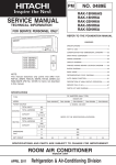
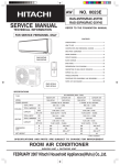
SPECIFICATIONS
CARACTERISTIQUES GENERALES
DC INVERTER INVERSEUR C.C.
TYPE
TYPE
INDOOR UNIT
UNITÉ INTÉRIEURE
MODEL
MODÈLE
POWER SOURCE SOURCE D'ALIMENTATION (PHASE/TENSION/FREQUENCE)
COOLING
RÉFRIGÉRATION
HEATING
CHAUFFAGE
OUTDOOR UNIT
UNITÉ EXTÉRIEURE
RAC-35NX2
RAF-35NX2
TOTAL INPUT
PUISSANCE ABSORBEE TOTALE (W)
TOTAL AMPERES
AMPERES TOTAUX
1ø, 220V - 230V, 50Hz
1,090 (155 - 1,460)
(A)
5.22- 4.99
(kW)
3.5 (0.9 - 4.0)
CAPACITY
CAPACITE
(B.T.U./h)
11,940 (3,070 - 13,650)
TOTAL INPUT
PUISSANCE ABSORBEE TOTALE
(W)
1,100 (115 - 1,440)
TOTAL AMPERES
AMPERES TOTAUX
(A)
5.32 - 5.09
(kW)
4.2 (0.9 - 5.0)
CAPACITY
DIMENSIONS
NET WEIGHT
CAPACITE
DIMENSIONS
POIDS NET
(B.T.U./h)
(mm)
14,330 (3,070 - 17,060)
W, L
760
H, H
600
548
D, P
235
288 (+47)※
(kg)
14
750 (+91)※
35
※After installation
Après installation
SPECIFICATIONS AND PARTS ARE SUBJECT TO CHANGE FOR IMPROVEMENT.
LES SPECIFICATIONS ET PIECES DETACHEES PEUVENT CHANGER POUR ETRE AMELIOREES.
ROOMINDOOR
AIR
CONDITIONER
UNIT + OUTDOOR UNIT
JUNE 2010
Hitachi Household Appliances(Wuhu) Co., Ltd.
!
" #
*
$
"
$ %
* !
: ;
< =
> ;
;
! *??@JZ
[ ;
? #
=
Z
DANGER
\\
#
]
^
]
_
^
`
]
%
b
c
b
`
b
c
]]
]
d
`
=
`
]
`
_
`
]
]
d
_
_
]
" #bb
]
c
]
*
$
"
$ #b
j
]
c
]
^`
* ;
`
c
]
]
;
`
qc
]
^
: %
c
]
`
]]
]
]]]]
< %
``
]
]
_^]
u^
]
]
`=
> v]
`
`
]
`
Z
]
c
]
^! ]
]b
*??@ZZ
[ #d
`]]]
]
_
d`
`
d
]
_q
`]c
d]
^
? %`
`c
]]
b
%
^
c
w]
x
]
DANGER
y
#]
J
c
^
{
_
–2–
WORKING STANDARDS FOR PREVENTING BREAKAGE OF SEMICONDUCTORS
1. Scope
The standards provide for items to be generally observed in carrying and handling semiconductors in
relative manufactures during maintenance and handling thereof. (They apply the same to handling of
abnormal goods such as rejected goods being returned.)
2. Object parts
(1) Microcomputer
(2) Integrated circuits (I.C.)
(3) Field effective transistor (F.E.T.)
(4) P.C. boards or the like to which the parts mentioned in (1) and (2) of this paragraph are equipped.
3. Items to be observed in handling
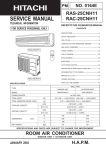
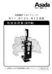
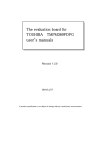
(1) Use a conductive container for carrying and storing of parts. (Even rejected goods should be handled in
the same way.)
IC
A conductive polyvinyl bag
IC
CH I
IC40
1TH1
,188
Conductive sponge
UV
HITA
Fig. 1 Conductive container
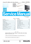
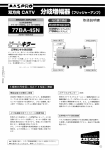
(2) When any part is handled uncovered (in counting, packing and the like), the handling person must
always use himself as a body earth. (Make yourself a body earth by passing one M ohm earth
resistance through a ring or bracelet.)
(3) Be careful not to touch the parts with your clothing when you hold a part even if a body earth is
being taken.
(4) Be sure to place a part on a metal plate with grounding.
(5) Be careful not to fail to turn off power when you repair the printed circuit board.
try to repair the printed circuit board on a grounded metal plate.
At the same time,
Body earth (Elimik conductive band)
Clip for connection with
a grounding wire
1MΩ
Fig. 2 Body earth
–3–
PREVENTION DES DOMMAGES AUX SEMI-CONDUCTEURS
1. Champ d'application
Pour éviter d'endommager les semi-conducteurs utilisés dans les unités, lors de chaque intervention
d'entretien ou de réparation, vous devez observer des précautions spéciales. Les mêmes précautions
doivent être prises lors de la manipulation d'organes défectueux qui doivent être retournés en usine.
2. Pièces détachées de l'appareillage.
(1) Microprocesseur
(2) Circuits intégrés (C.I.)
(3) Transistor à effet de champ (T.E.C)
(4) Circuits imprimés sur lesquels se trouvent implantés les composants (1) et (2).
3. Précautions de manipulation
(1) Pour transporter ou stocker un semi-conducteur, placez-le dans un emballage conducteur. Procéder de
même avec un composant défectueux.
C.I.
Sac en polyvinyle
conducteur
C.I.
CH I
IC40
1TH1
,188
Eponge
conductrice
UV
HITA
Fig. 1 Emballage conducteur
(2) Lorsque vous manipulez des composants qui ne sont pas protégés (par exemple pour les compter ou
les emballer), vous devez veiller à ce que votre corps soit électriquement relié à la terre. Pour cela,
portez un bracelet conducteur. Reliez le bracelet à une résistance de 1MΩ et celle-ci à la terre par
l'intermédiaire d'un conducteur.
(3) Veillez en outre à ce que vos vêtements ne viennent jamais en contact avec le composant même si
votre corps est relié à la terre.
(4) Déposez le composant sur une surface métallique correctement mise à la terre.
(5) Sous aucun prétexte, n'omettez de couper l'alimentation avant de procéder à une réparation sur un
circuit imprimé. Par ailleurs, l'intervention sur le circuit imprimé doit se faire alors que celui-ci repose
sur une surface métallique mise à la masse.
Bracelet de mise à la terre du corps
(Bande conductrice Elimik)
Pince de connexion avec
fil de mise à la terre
1MΩ
Fig. 2 Mise à la terre du corps
–4–
(6) Use a three wire type soldering iron including a grounding wire.
Metal plate (of Al. stainless steel, etc.)
Bare copper wire (for body earth)
Working table
Resistor 1MΩ(1/2W)
Staple
Earth wire
Fig.3 Grounding of the working table
soldering iron
Grounding wire
Screw stop at the screwed
part using a rag plate
Fig.4 Grounding a solder iron
Use a high insulation mode (100V, 10MΩ or higher) when ordinary iron is to be used.
(7) In checking circuits for maintenance, inspection, or some others, be careful not to have the test probes
of the measuring instrument short circuit a load circuit or the like.
–5–
(6) Le fer à souder doit être alimenté par un câble à trois conducteurs (dont un pour la mise à la terre).
Surface métallique (aluminium, acier inoxydable, etc.)
Fil de cuivre nu
(pour mise à la
terre du corps)
Plan de travail
Résistance de
1MΩ (1/2W)
Agrafe
Câble de masse
Fig.3 Mise à la terre d'un plan de travail
fer à souder
Câble de masse
Poser ici une rondelle éventail et la visser
Fig.4 Mise à la terre d'un fer à souder
Vous pouvez également utiliser un fer à souder ordinaire dans la mesure où il est parfaitement
isolé (au moins 10MΩ sous 100V).
(7) Pendant le contrôle des circuits au cours des opérations d'entretien ou d'inspection, évitez à tout prix la
mise en court-circuit de la charge par les pointes de contact de l'appareil de mesure.
–6–
CAUTION
1. In quiet operation or stopping the running, its heard slight flowing noise of
refrigerant in the refrigerating cycle occasionally, but this noise is not abnormal
for the operation.
2. When it thunders near by, it is recommend to stop the operation and to
disconnect the power cord plug from the power outlet for safety.
3. The room air conditioner dose not start automaticaly after recovery of the
electric power failure for preventing fuse blowing.
Re-press START / STOP
button after 3 minutes from when unit stopped.
4. If the room air conditioner is stopped by adjusting thermostat, or missoperation,
and re-start in a moment, there is occasion that the cooling and heating
operation does not start for 3 minutes, it is not abnormal and this is the result
of the operation of IC delay circuit. This IC delay circuit ensures that there is
no danger of blowing fuse or damaging parts even if operation is restarted
accidentally.
5. This room air conditioner should not be used at the cooling operation when the
outside temperature is below –10˚C (14˚F).
6. This room air conditioner (the reverse cycle) should not be used when the
outside temperature is below –15˚C (5˚F).
If the reverse cycle is used under this condition, the outside heat exchanger is
frosted and efficiency falls.
7. When the outside heat exchanger is frosted, the front is melted by operating
the hot gas system, it is not trouble that at this time fan stops and the vapour
may rise from the outside heat exchanger.
–7–
ATTENTION
1. Dans certaines conditions et pendant un arrêt de fonctionnement, on peut
parfois entendre le bruit du réfrigérant circulant dans les canalisations; ce bruit
n'a rien d'anormal.
2. Pour des raisons de sécurité, il est conseillé, pendant un orage, d'arrêter le
fonctionnement du système en coupant l'alimentation électrique.
3. Pour éviter que le fusible ne fonde, le climatiseur ne démarre pas
automatiquement après une panne de secteur. La remise en marche suppose
une pression sur la touche START / STOP après un délai d'au moins 3 minutes
suivant l'arrêt.
4. Si le climatiseur est arrêté à la suite d'un réglage de thermostat, ou à cause
d'une fausse manoeuvre et qu'il est remis en route, il se peut que la
réfrigération ou le chauffage ne reprenne qu'après 3 minutes. Ce phénomène
est normal et dû à un relais temporisé.
Ce relais temporisé a pour rôle
d'éviter que le fusible ne fonde ou que des composants ne soient
endommagés par une remise en service accidentelle.
5. Ce climatiseur ne doit pas être utilisé pour réfrigérer une pièce lorsque la
température extérieure est inférieure à –10˚C (14˚F).
6. Ce climatiseur ne doit pas être utilisé lorsque la température extérieure est
inférieure à –15˚C (5˚F).
En effet, dans ce cas, l'échangeur de chaleur extérieur gèle et le rendement
chute considérablement.
7. Quand l'échangeur de chaleur extérieur est givré, les gaz chauds peuvent
entraîner une vaporisation de l'eau accumulée sur la face avant. Ce n'est pas
un problème si à ce moment-là le ventilateur s'arrête et il se peut que de la
vapeur se dégage de l'échangeur de chaleur extérieur.
–8–
SPECIFICATIONS
CARACTERISTIQUES GENERALES
RAF-35NX2
RAC-35NX2
20W (DC35V)
40W (DC380V)
MODEL
MODÈLE
FAN MOTOR
MOTEUR DE VENTILATEUR
FAN MOTOR CAPACITOR
CONDENSATEUR DE MOTEUR
DE VENTILATEUR
NO
NON
FAN MOTOR PROTECTOR
PROTECTION DU MOTEUR
DE VENTILATEUR
NO
NON
COMPRESSOR
COMPRESSEUR
OVER HEAT PROTECTOR
PROTECTION CONTRE LES
SURCHAUFFES
NO
NON
YES
OUI
OVERLOAD RELAY
RELAIS DE SURCHARGE
NO
NON
YES
OUI
FUSE (for MICRO COMPUTER)
FUSIBLE
(pour MICROPROCESSEUR)
NO
NON
3A
POWER RELAY, STICK RELAY
RELAIS DE PUISSANCE,
RELAIS AUTOEXCITE
NO
NON
G4A
POWER SWITCH
INTERRUPTEUR D'ALIMENTATION
TEMPORARY SWITCH
INTERRUPTEUR AUXILIAIRE
YES
OUI
NO
NON
SERVICE SWITCH
INTERRUPTEUR DE SERVICE
NO
NON
YES
OUI
TRANSFORMER
TRANSFORMATEUR
NO
NON
NO
NON
VARISTOR
VARISTANCE
NO
NON
NOISE SUPPRESSOR
ANTIPARASITAGE
NO
NON
THERMOSTAT
THERMOSTAT
ASC092CD-A8J K
NO
NON
YES (IC) OUI (IC)
450NR
NO
NON
NO
NON
REMOTE CONTROL SWITCH (LIQUID CRYSTAL)
YES (RAR-3U1)
NO
INTERRUPTEUR DE TÉLÉCOMMANDE (CRISTAUX LIQUIDES)
OUI (RAR-3U1)
NON
FUSE CAPACITY
A INRUSH - WITH STAND TYPE
CALIBRE DE FUSIBLE
A RETARDE-AVEC STAND TYPE
UNIT
900g
UNITÉ
REFRIGERANT CHARGING VOLUME
(R410A)
CHARGE EN RÉFRIGÉRANT
(R410A)
WITHOUT REFRIGERANT BECAUSE COUPLING
PIPES
CANALISATIONS
IS FLARE TYPE.
SANS RÉFRIGÉRANT EN RAISON DU
(MAX. 20m)
RACCORDEMENT FLARE.
–9–
+2:7286(
PRECAUTIONS DURING OPERATION
SAFETY PRECAUTION
The product shall be operated under the manufacturer specification and not for any
other intended use.
Please read the “Safety Precaution” carefully before operating the unit to ensure correct usage of the unit.
Pay special attention to signs of “ Warning” and “ Caution”. The “Warning” section contains matters
which, if not observed strictly, may cause death or serious injury. The “Caution” section contains matters
which may result in serious consequences if not observed properly. Please observe all instructions strictly to
ensure safety.
The signs indicate the following meanings. (The following are examples of signs.)
PRECAUTIONS DURING INSTALLATION
PROHIBITION
PROHIBITION
Please ensure that outdoor mounting frame is always stable, firm and without
defect. If not, the outdoor unit may collapse and cause danger.
Please ask your sales agent or qualified technician for the installation of your unit.
Water leakage, short circuit or fire may occur if you install the unit by yourself.
WARNING
Please use earth line.
Do not place the earth line near water or gas pipes, lightning-conductor, or the
earth line of telephone. Improper installation of earth line may cause electric
shock or fire.
PROHIBITION
CONNECT EARTH LINE
PROHIBITION
Be sure to use the specified piping set for R410A. Otherwise, this may result in
broken copper pipes or faults.
A circuit breaker should be installed depending on the mounting site of the unit.
Without a circuit breaker, the danger of electric shock exists.
²²
CAUTION
Do not install the unit near a location where there is flammable gas. The outdoor unit
may catch fire if flammable gas leaks around it. Piping shall be suitable supported
with a maximum spacing of 1m between the supports.
Do not place plants directly under the air flow as it is bad for the plants.
PROHIBITION
PROHIBITION
"OFF"
Be sure to stop the operation by using the remote controller and turn off the circuit
breaker during cleaning, the high-speed fan inside the unit may cause danger.
CAUTION
Turn off the circuit breaker if the unit is not be operated for a long period.
"OFF"
PROHIBITION
PRECAUTIONS DURING SHIFTING OR MAINTENANCE
Should abnormal situation arise (like burning smell), please stop operating the unit
and remove plug from the socket. Contact your agent. Fault, short circuit or fire may
occur if you continue to operate the unit under abnormal situation.
Do not climb on the outdoor unit or put objects on it.
PROHIBITION
"OFF"
Please contact your agent for maintenance. Improper self maintenance may cause electric shock
and fire.
Please contact your agent if you need to remove and reinstall the unit. Electric shock or fire may occur
if you remove and reinstall the unit yourself improperly.
When operating the unit with the door and windows opened, (the room humidity is
always above 80%) and with the air deflector facing down or moving automatically
for a long period of time, water will condense on the air deflector and drips down
occasionally. This will wet your furniture. Therefore, do not operate under such
condition for a long time.
PRECAUTIONS DURING OPERATION
PROHIBITION
Avoid an extended period of direct air flow for your health.
PROHIBITION
PROHIBITION
WARNING
Do not wash the unit with water or place a water container such as a vase on the
indoor unit.
Electrical leakage could be present and cause electric shock.
Please ensure smooth flow of water when installing the drain hose.
Make sure that a single phase 220V or 230V power source is used.
The use of other power sources may cause electrical components to overheat and
lead to fire.
WARNING
Do not direct the cool air coming out from the air-conditioner panel to face household
heating apparatus as this may affect the working of apparatus such as the electric
kettle, oven etc.
Do not put objects like thin rods into the panel of blower and suction side because
the high-speed fan inside may cause danger.
Do not use any conductor as fuse wire, this could cause fatal accident.
PROHIBITION
During thunder storm, disconnect the plug top and turn off the circuit breaker.
If the amount of heat in the room is above the cooling or heating capability of the unit
(for example: more people entering the room, using heating equipments and etc.),
the preset room temperature cannot be achieved.
Indoor unit cleaning must be performed by authorized personnel only. Consult your
sales agent.
Using a commercially available detergent or similar can damage the plastic parts
or clog the drain pipe, causing water to drip with potential electric shock hazard.
DON’T TOUCH
PROHIBITION
PROHIBITION
Do not touch the air outlet, bottom surface and aluminum fin of the outdoor
unit.
You may get hurt.
Do not touch the refrigerant pipe and connecting valve.
Burns may result.
"OFF"
DON’T TOUCH
Spray cans and other combustibles should not be located within a meter of the air
outlets of both indoor and outdoor units.
As a spray can’s internal pressure can be increased by hot air, a rupture may result.
–2–
PROHIBITION
This appliance is not intended for use by young children or infirm persons unless they have been
adequately supervised by a responsible person to ensure that they can use this appliance safely.
Young children should be supervised to ensure that they do not play with the appliance.
–3–
SPANISH
Do not reconstruct the unit.
Water leakage, fault, short circuit or fire may occur if you reconstruct the unit by
yourself.
STRICTLY OBSERVE
PRECAUTIONS
FRANÇAIS
Please keep this manual after reading.
ITALIANO
When operating the unit with burning equipments, regularly ventilate the
room to avoid oxygen insufficiency.
Indicates the instructions that must be followed.
DEUTSCH
Do not attempt to operate the unit with wet hands, this could cause fatal accident.
DON'T WET
РУССКИЙ ∂ÏÏËÓÈο PORTUGUÊS
This sign in the figure indicates prohibition.
PROHIBITION
ENGLISH
02'(/5$)1;5$&1;
Indoor unit
indicators
Air filter
Signal receiver
Front panel
RAC-25NX2
INDOOR UNIT INDICATORS
OPERATION lamp
Remote controller
This lamp lights during operation.
During heating, the operation indicator may
blink, blowing very lightly or totally stopping
under the following conditions:
(1) During preheating (heating
operation)
For about 2~3 minutes after start up.
(2) During defrosting (heating
operation)
Defrosting will be performed about
once an hour when frost forms on the
heat exchanger of the outdoor unit, for
5~10 minutes each time. (If the piping
length used is longer than usual, frost
will likely to form.)
FILTER lamp
²²
This lamp lights when the
device is operated for a total
of about 200 hours, it is time
to clean the filter. The lamp
goes out when the “ (AUTO
SWING)” button is pressed
while the operation is stopped.
RAC-35NX2
RAC-50NX2
TIMER lamp
This lamp lights when the timer is
working.
MODEL NAME AND DIMENSIONS
MODEL
WIDTH
HEIGHT
DEPTH
RAF-25NX2
RAF-35NX2
RAF-50NX2
(INDOOR UNIT)
760mm
600mm
235mm
RAC-25NX2*
700mm
505mm
258mm
RAC-35NX2*
750mm
548mm
288mm
RAC-50NX2*
792mm
600mm
299mm
HOW TO OPEN OR CLOSE THE FRONT PANEL
* OUTDOOR UNIT for single split model.
Top left and right corners
Open the front panel
1. To open the front panel, use the remote controller to stop unit
operation. Then press at the top left and right corners of the front
panel.
2. Grasp the left and right sides of the front panel and open it toward
you.
Close the front panel
1. To close the front panel, press the upper center part of the front
panel.
2. Press at the top left and right corners of the front panel.
Upper center part
–4–
–5–
DEUTSCH
TEMPORARY SWITCH
If the remote controller does not work due to
battery failure, press this switch to start and stop
operation.
• This temporary operation will be at the most
recent setting made. (The unit will immediately
go into automatic operation once power is
switched on.)
FRANÇAIS
TEMPORARY SWITCH
Horizontal air
deflector
ITALIANO
TEMPORARY SWITCH
SPANISH
OUTDOOR UNIT FOR
SINGLE SPLIT MODEL
РУССКИЙ ∂ÏÏËÓÈο PORTUGUÊS
INDOOR UNIT
ENGLISH
NAMES AND FUNCTIONS OF EACH PART
²²
HEAT
DEHUMIDIFY
COOL
FAN
FAN SPEED
SILENT
LOW
MED
HI
SLEEPING
STOP (CANCEL)
START (RESERVE)
START/STOP
TIME
TIMER SET
TIMER SELECTOR
ON TIMER
OFF TIMER
AUTO SWING
Precautions for Use
• Do not put the remote controller in the following places.
• In direct sunlight.
• In the vicinity of a heater.
• Handle the remote controller carefully. Do not drop it on the floor, and protect
it from water.
• Once the outdoor unit stops, it will not restart for about 3 minutes (unless you
turn the power switch off and on or unplug the power cord and plug it in again).
This is to protect the device and does not indicate a failure.
• If you press the FUNCTION selector button during operation, the device may
stop for about 3 minutes for protection.
–6–
AUTOMATIC OPERATION
The device will automatically determine the mode of operation, HEAT, COOL, or DEHUMIDIFY, depending
on the initial room temperature. The selected mode of operation will change when the room temperature
varies. However, the mode of operation will not change when indoor unit connected to multi type outdoor
unit.
Press the FUNCTION selector so that the display indicates the
(AUTO) mode of operation.
1
• When AUTO has been selected, the device will automatically
determine the mode of operation, HEAT or COOL depending on
the current room temperature.
• When AUTO is first selected, the device will determine the current
room temperature and select the proper operation mode
accordingly.
• When the air conditioner has adjusted the room's temperature to
the near preset temperature, it will begin to monitor operation. If
the room temperature subsequently changes, the air conditioner
will once again select the appropriate operation (heating or cooling)
to adjust the temperature to the preset temperature. The monitoring
operation range is + 3°C relative to the preset temperature.
• If the mode automatically selected by the unit is not satisfactory,
manually change the mode setting (heat, dehumidify, cool or fan).
START
STOP
Press the
(START/STOP) button.
Operation starts with a beep.
Press the button again to stop operation.
■ As the settings are stored in memory in the remote controller, you only have
to press the
(START/STOP) button next time.
You can raise or lower the temperature setting as necessary by maximum
of 3°C.
Press the temperature button and the temperature
setting will change by 1°C each time.
• The preset temperature and the actual room temperature may vary
somewhat depending on conditions.
Press the
(FAN SPEED) button. AUTO, LOW and SILENT are available.
–7–
ENGLISH
DEUTSCH
FRANÇAIS
● Signal emitting window/transmission sign
Point this window toward the indoor unit when controlling it.
The transmission sign blinks when a signal is sent.
● Display
This indicates the room temperature selected, current time, timer status, function
and intensity of circulation selected.
● START/STOP button
Press this button to start operation. Press it again to stop operation.
● AUTO SWING button
Controls the angle of the horizontal air deflector.
● FAN SPEED selector
This determines the fan speed. Every time you press this button, the intensity of
(HI) to
(MED) to
(LOW) to
circulation will change from (AUTO) to
(SILENT). (This button allows selecting the optimal or preferred fan speed
for each operation mode.)
● SLEEP button
Use this button to set the sleep timer.
● TEMPERATURE buttons
Use these buttons to raise or lower the temperature setting. (Keep pressed, and
the value will change more quickly.)
● TIME button
Use this button to set and check the time.
● RESET button
Press this button after the batteries are replaced or when some irregular operation
is found.
● FUNCTION selector
Use this button to select the operating mode. Every time you press it, the mode
will change from
(AUTO) to
(HEAT) to
(DEHUMIDIFY) to
(COOL)
and to (FAN) cyclically.
● FAN SPEED selector
● AUTO SWING button
● TIMER control
Use these buttons to set the timer.
● OFF-TIMER button Select the turn OFF time.
● ON-TIMER button Select the turn ON time.
● RESERVE button Time setting reservation.
● CANCEL button Cancel time reservation.
• If there is a power failure, operation will be automatically restarted when the power is resumed with
previous operation mode and airflow direction.
(As the operation is not stopped by remote controller.)
• If you intend not to continue the operation when the power is resumed, switch off the power supply.
When you switch on the circuit breaker, the operation will be automatically restarted with previous
operation mode and airflow direction.
Note: 1. If you do not require Auto Restart Control, please consult your sales agent.
2. Auto Restart Control is not available when Timer or Sleep Timer mode is set.
ITALIANO
• This controls the operation of the indoor unit. The range of control is about 7 meters. If indoor lighting is controlled
electronically, the range of control may be shorter, in some cases, the control signal may not be received.
This unit can be fixed on a wall using the fixture provided. Before fixing it, make sure the indoor unit can be
controlled from the remote controller.
• Handle the remote controller with care. Dropping it or getting it wet may compromise its signal transmission
capability.
• After new batteries are inserted into the remote controller, the unit will initially require approximately 10 seconds
to respond to commands and operate.
SPANISH
■ Auto Restart Control
REMOTE CONTROLLER
AUTO
VARIOUS FUNCTIONS
РУССКИЙ ∂ÏÏËÓÈο PORTUGUÊS
NAMES AND FUNCTIONS OF EACH PART
(AUTO)
: The fan speed changes automatically according
to the temperature of the air which blows out.
(HI)
: Economical as the room will become warm
quickly.
But you may feel a chill at the beginning.
(MED)
: Quiet.
(LOW)
: More quiet.
(SILENT) : Silent.
²²
Set the desired room temperature with the TEMPERATURE buttons
(the display indicates the setting).
3
START
STOP
The temperature setting and the actual room temperature may vary
somewhat depending on conditions.
START
STOP
Press the
■ When you want to change the operation mode, please use the FUNCTION
selector.
■ Set the desired temperature is available.
■ You also can use the FUNCTION selector to select this operation.
■ Dehumidifying Function
• Dehumidifying takes place with a target temperature which is slightly lower than the room temperature
setting. (However, target temperature is 16°C for a temperature setting of 16°C.)
If the room temperature becomes lower than the target value, operation stops. If the room temperature
becomes higher than the target value, operation restarts.
• The preset room temperature may not be reached depending on the number of people present in the room
conditions.
Press the
(START/STOP) button. Heating operation starts with
a beep. Press the button again to stop operation.
■ As the settings are stored in memory in the remote controller, you only have
(START/STOP) button next time.
to press the
■ Defrosting
Defrosting will be performed about once an hour when frost forms on the heat exchange of the outdoor unit,
for 5~10 minutes each time.
During defrosting operation, the operation lamp blinks in cycle of 3 seconds on and 0.5 second off.
The maximum time for defrosting is 20 minutes.
However, if it is connected to multi type outdoor unit, the maximum time for defrosting is 15 minutes.
(If the piping length used is longer than usual, frost will likely to form.)
–8–
ENGLISH
(START/STOP) button.
–9–
FRANÇAIS
2
(FAN SPEED) button (the
Press the FUNCTION selector so that the display indicates
(DEHUMIDIFY).
Press the (FAN SPEED) button to select LOW and SILENT.
ITALIANO
Set the desired FAN SPEED with the
display indicates the setting).
1
SPANISH
1
Press the FUNCTION selector so that the display indicates
(HEAT).
Use the device for dehumidifying when the room temperature is over 16°C.
When it is under 15°C, the dehumidifying function will not work.
РУССКИЙ ∂ÏÏËÓÈο PORTUGUÊS
• Use the device for heating when the outdoor temperature is under 21°C.
When it is too warm (over 21°C), the heating function may not work in order to protect the device.
• In order to keep reliability of the device, please use this device above -15°C of the outdoor temperature.
DEUTSCH
DEHUMIDIFYING OPERATION
HEATING OPERATION
1
You can use the device simply as an air circulator. Use this function to dry the interior of the indoor unit
at the end of summer.
Press the FUNCTION selector so that the display indicates
(COOL).
Set the desired FAN SPEED with the
display indicates the setting).
1
Press the FUNCTION selector so that the display indicates
Press the
(FAN SPEED) button.
(AUTO)
: The FAN SPEED is HI at first and varies to MED
automatically when the preset temperature has
been reached.
(HI)
: Economical as the room will become cool quickly.
(MED)
: Quiet.
(SILENT) : Silent.
(LOW)
: More quiet.
2
(FAN).
(FAN SPEED) button (the
2
(HI)
: The strongest air blow.
(MED)
: Quiet.
(LOW)
: More quiet.
ENGLISH
Use the device for cooling when the outdoor temperature is –10 to 42°C.
If humidity is very high (over 80%) indoors, some dew may form on the air outlet grille of the indoor unit.
DEUTSCH
FAN OPERATION
FRANÇAIS
COOLING OPERATION
START
STOP
The temperature setting and the actual room temperature may vary
somewhat depending on conditions.
Press the
(START/STOP) button. Cooling operation starts with
a beep. Press the button again to stop operation. The cooling function
does not start if the temperature setting is higher than the current
(OPERATION) lamp lights).
room temperature (even though the
The cooling function will start as soon as you set the temperature
below the current room temperature.
■ As the settings are stored in memory in the remote controller, you only have
(START/STOP) button next time.
to press the
– 10 –
FAN SPEED (AUTO) … When the AUTO fan speed mode is set in the cooling/heating operation:
For the heating operation
• The fan speed will automatically change according to the temperature of
discharged air.
• As room temperature reaches the preset temperature, a very light breeze
will blow.
For the cooling operation
• Operation starts in the “HI” mode to reach the preset temperature.
• As room temperature approaches the preset temperature, fan speed
automatically switches to “LOW”.
– 11 –
SPANISH
²²
3
Press the
(START/STOP) button. Fan operation starts with a beep.
Press the button again to stop operation.
Set the desired room temperature with the TEMPERATURE buttons
(the display indicates the setting).
РУССКИЙ ∂ÏÏËÓÈο PORTUGUÊS
START
STOP
ITALIANO
(SILENT) : Silent.
• To check the current time setting, press the (TIME)
button twice.
The setting of the current time is now complete.
AM
PM
PM
PM
Example: The current time is 1:30p.m.
OFF TIMER
ON TIMER
1
Press the
(OFF-TIMER)
button. The
(OFF) mark blinks on
the display.
OFF-Timer
RESERVE
2
3 Point the signal window of the remote controller toward the indoor unit, and
Set the turn-off time with the
TIMER control button.
press the (RESERVE) button.
(OFF) mark starts lighting instead of flashing and the
(RESERVED)
The
sign lights. A beep occurs and the
(TIMER) lamp lights on the indoor unit.
Stop
Start
PM
CANCEL
AM
You can set the device to turn off at
the present time.
PM
1
ON-Timer
Stop
The device will turn on at the
designated times.
Press the (ON-TIMER) button.
The
(ON) mark blinks on the
display.
Start
2
press the (RESERVE) button.
(ON) mark starts lighting instead of flashing and the
(RESERVED)
The
(TIMER) lamp lights on the indoor unit.
sign lights. A beep occurs and the
²²
AM
1
Start
Stop
Press the
(OFF-TIMER) button
so that the
(OFF)
mark blinks.
• The device will turn on (off) and
off (on) at the designated times.
• The switching occurs first at the
preset time that comes earlier.
• The arrow mark appearing on the
display indicates the sequence of
switching operations.
3 Press the (ON2 Set the turn-off time with TIMER)
button so that the
the TIMER control button.
Press the (RESERVE)
button.
4
Set the turn-on time with the
TIMER control button.
(OFF) mark lights and
the
(ON) mark blinks.
Example: The device will turn off at 11:00p.m.
The setting of turn-off time is now complete.
3 Point the signal window of the remote controller toward the indoor unit, and
Set the turn-on time with the
TIMER control button.
AM
ON/OFF-Timer
• The time indication will disappear automatically in 10
seconds.
AM
Example:
The device will automatically turn on earlier so that
the preset temperature can be reached at 7:00a.m.
The setting of the turn-on time is now complete.
5
Point the signal window of the remote controller toward the indoor unit, and
press the (RESERVE) button.
The (ON) mark starts lighting instead of flashing and the (RESERVED) sign
(TIMER) lamp lights on the indoor unit.
lights. A beep occurs and the
PM
PM
PM
PM
PM
AM
AM
AM
Example:
The device will turn off at 10:30p.m. and then
automatically turn on earlier so that the preset
temperature can be reached at 7:00a.m.
The settings of the turn-on/off times are now
complete.
• The timer may be used in three ways: off-timer, on-timer and ON/OFF (OFF/ON)-timer. Set the current time
at first because it serves as a reference.
How to Cancel Reservation
Point the signal window of the remote controller toward the indoor unit, and press the (CANCEL)
button.
The (RESERVED) sign goes out with a beep and the (TIMER) lamp turns off on the indoor unit.
• As the time settings are stored in memory in the remote controller, you only have to press the
button is order to use the same settings next time.
NOTE
You can set only one of the OFF-timer,
ON-timer and ON/OFF-timer.
– 12 –
– 13 –
(RESERVE)
ENGLISH
(TIME) button
again. The time indication starts
lighting instead of flashing.
DEUTSCH
3 Press the
FRANÇAIS
2
Set the current time with
the TIMER control button.
ITALIANO
(TIME) button.
After you change the
batteries;
SPANISH
1 Set the
Time
TIME
(current time)
РУССКИЙ ∂ÏÏËÓÈο PORTUGUÊS
HOW TO SET THE TIMER
Indication
1 hour
Sleep Timer
3 hours
7 hours
Sleep timer off
Sleep Timer: The device will continue working for the desired number
of hours and then turn off.
Point the signal window of the remote controller toward the indoor unit,
and press the SLEEP button.
The timer information will be displayed on the remote controller.
The TIMER lamp lights with a beep from the indoor unit. When the
sleep timer has been set, the display indicates the turn-off time.
Example: If you set 3 hours sleep time
at 11:38 p.m., the turn-off time is
2:38 a.m..
²²
Start
1
Set the ON-timer.
2
Press the
AM
• When the “ (AUTO SWING)” button is
pressed while the operation is stopped,
the horizontal air deflector moves and
stops at the position where the air outlet
closes.
The device will be turned off by the sleep timer
and turned on by on-timer.
• When the auto swing operation is
performed, if the horizontal air deflector
is moved manually, the swinging range
may drift. However, it will return to the
original operation range after a short
time.
For heating:
In this case, the device will turn off in 2
hours (at 1:38 a.m.) and will turn on
early so that the present temperature
will be almost reached at 6:00 a.m. next
morning.
Vertical air deflector
2
How to Cancel Reservation
Vertical
about
When cooling, 30°
dehumidifying
about 40°
• Use the horizontal air deflector within
the adjusting range shown in the right
figure.
(SLEEP) button and set the sleep timer.
AM
When
heating,
about 50°
ITALIANO
AM
Sleep
timer
• If the “
(AUTO SWING)” button is
pressed once, the horizontal air deflector
swings up and down. If the button is
pressed again, the deflector stops in its
current position.
SPANISH
SLEEP
2 hours
Adjustment of the conditioned air in the upward
and downward directions.
The horizontal air deflector is automatically set to
the proper angle suitable for each operation. The
deflector can be swung up and down continuously
and also set to the desired angle using the “
(AUTO SWING)” button.
DEUTSCH
Mode
1
Point the signal window of the remote controller toward the indoor unit, and press the (CANCEL)
button.
The (RESERVED) sign goes out with a beep and the (TIMER) lamp turns off on the indoor unit.
Adjustment of the conditioned air to the left and
right.
Hold the vertical air deflector as shown in the figure
and adjust the conditioned air to the left and right.
NOTE
If you set the sleep timer when the off-time or on/off
timer has been set earlier, the sleep timer becomes
effective instead of the off - or on/off-timer set earlier.
– 14 –
CAUTION
•
When operating the unit in cooling operation with the air deflector facing down and moving automatically
for a long period of time, water will be condensed on the air deflector and drips down occasionally. This
will wet your furniture.
– 15 –
FRANÇAIS
Set the current time at first if it is not set before (see the pages for setting the current time).
(SLEEP) button and the display changes as shown below.
Press the
ENGLISH
ADJUSTING THE AIR DEFLECTORS
РУССКИЙ ∂ÏÏËÓÈο PORTUGUÊS
HOW TO SET THE SLEEP TIMER
ENGLISH
Remove the cover as shown in the figure and remove the
old batteries.
WARNING
• Before cleaning, stop unit operation with the remote controller and turn off the circuit breaker.
CAUTION
Push and pull to
the direction of
arrow mark ▼.
CAUTION
1. Do not mix new and old batteries, or different type of
batteries together.
2. Remove the batteries when you do not use the remote
controller for 2 or 3 months.
Cover
• Do not expose the unit to water as it may cause an electric shock.
• For cleaning inside the air conditioner, consult your sales agent.
• Avoid using detergent when cleaning the heat exchanger of the indoor unit. Unit failure may result.
• When cleaning the heat exchanger with a vacuum cleaner, make sure to wear gloves so as not to injure your
hands on the heat exchanger fins.
FRANÇAIS
Install the new batteries.
The direction of the batteries should match the marks in
the case.
1. AIR FILTER
Clean the air filter, as it removes dust inside the room.
Be sure to clean the filter once every two weeks so as not to consume electricity unnecessarily.
TEMPORARY SWITCH
²²
CIRCUIT BREAKER
TEMPORARY SWITCH
1
Open the front panel.
2
Remove the filters.
3
Remove dust of the filters using a vacuum cleaner.
4
Attach the filters.
5
Close the front panel.
ITALIANO
PROCEDURE
If the remote controller does not work due to battery
failure, press this switch to start and stop operation.
• This temporary operation will be at the setting made
most recently. (The unit will immediately go into
automatic operation once power is switched on.)
• To open the front panel, use the remote controller to stop unit
operation. Then press at the top left and right corners of the front
panel.
• Grasp the left and right sides of the front panel and open it toward you.
SPANISH
2
When you do not use the room air conditioner, set the circuit breaker to “OFF”.
HOW TO USE THE AIR CONDITIONER EFFECTIVELY
1. An average room temperature setting is probably the best for you as well as being
economical.
• Excessive cooling or heating is not recommended for health reasons. High electricity
bills may also result.
• Close the curtains or blinds to prevent heat from flowing into or escaping the room as
well as to make more effective use of electricity.
2. At intervals, the doors and windows should be opened to let fresh air in.
CAUTION
Make sure the room is ventilated when operating the air conditioner
at the same time as other heating appliances.
3. Using the timer is recommended before going to sleep or going out.
4. The following must never be used for cleaning the indoor and outdoor units:
• Benzine, thinner and scrub can damage plastic surfaces or coating.
• Hot water above 40°C can shrink the filter and deform plastic parts.
5. Do not block the air intake and air outlet.
• Do not block the air outlets and intakes of the indoor and outdoor units with curtains
or other obstacles which could degrade air conditioner performance and cause unit
failure.
– 16 –
• After using neutral detergent, wash with clean water and dry in
shade.
1. To close the front panel, press the upper center part of the front
panel.
2. Press at the top left and right corners of the front panel.
2
1
2
CAUTION
• Do not wash with hot water at more than 40°C. The filter may shrink.
• When washing it, shake off moisture completely and dry it in the shade; do not expose it directly to the sun.
The filter may shrink. And also use a soft sponge to wash. Using a scrubber or brush cause the metal film
on the surface to come off.
• Don’t operate the unit without filter. Fault may occur if you continue.
– 17 –
DEUTSCH
1
MAINTENANCE
РУССКИЙ ∂ÏÏËÓÈο PORTUGUÊS
HOW TO CHANGE THE BATTERIES IN THE REMOTE CONTROLLER
Removing
2 Grasp the left and right sides of the front panel
and pull it up to remove.
• When installing the air cleansing filters, remove the air filters and attach
them onto the hooks of the front cover frame.
• The cooling capacity is slightly weakened and the cooling speed becomes
slower when the air cleansing filters are used. So, set the fan speed to
“HIGH” when using it in this condition.
• The air cleansing filters can be used for 2 years.
Air cleansing filters
ITALIANO
FRANÇAIS
1 Press at the top left and right corners of the front
panel.
ENGLISH
5. AIR CLEANSING FILTERS (SPX-CFH15)
• Be sure to use both hands to grasp the front panel when removing it or attaching it.
DEUTSCH
2. HOW TO INSTALL AND REMOVE THE FRONT PANEL
Attaching
2 Close the front panel.
The front panel can be washed in water. It can be kept clean at all times.
• Front panel can be removed and washed in water. Gently clean the
front panel using a soft sponge.
• When the air conditioner is to be cleaned without removing the front
panel, clean both the body and remote controller with a dry soft cloth.
• Wipe off water completely. If water remains on the display section or
light receiver section, this could cause a malfunction.
SPANISH
²²
3. CLEANING OF FRONT PANEL
CAUTION
• Do not splash or direct water to the body of the unit when cleaning it as this may
cause short circuit.
• Never clean with hot water (above 40°C), benzine, gasoline, acid, thinner or a
brush, because it will damage the plastic surface and the coating.
B E N ZIN E
A
C
I
D
T H IN NER
4. MAINTENANCE AT BEGINNING OF LONG OFF PERIOD
• Activating air conditioner drying will keep the interior of the indoor unit
dry and prevent mold formation.
Air blow
• Turn off the circuit breaker.
– 18 –
– 19 –
РУССКИЙ ∂ÏÏËÓÈο PORTUGUÊS
1 Attach three front panel bearings to the axis of
the front cover. (Set the hook to face up.)
PLEASE CHECK THE FOLLOWING POINTS EVERY EITHER HALF YEARLY OR YEARLY. CONTACT YOUR
SALES AGENT SHOULD YOU NEED ANY HELP.
Heating Capability
2
WARNING
If the earth line is disconnected or faulty, unit failure or electric
shock hazard may result.
Check to see if the mounting frame has rusted excessively
or if the outdoor unit has tilted or become unstable.
It could collapse or fall, causing injury.
Cooling and Dehumidifying Capabilities
• If the heat present in a room exceeds the unit’s cooling capacity (for example, if there are many people in the room
or other heating appliances are used), the preset room temperature may not be reached.
AFTER SALES SERVICE AND WARRANTY
WHEN ASKING FOR SERVICE, CHECK THE FOLLOWING
VARIOUS FUNCTIONS
CONDITION
• When fan speed, room temperature are set with the remote controller before starting manual operation and
the buttons are released, the indication of settings will go off in 10 seconds and only the operation mode will
be displayed.
²²
• Pressing the
button while the unit is in operation will let the protective circuit work so that the unit will
not operate for approximately 3 minutes.
• During heating operation, the indoor unit’s color indicator lamp may flash with no air emitted for a while.
• If you feel cold wind during warming operation with the
(HI) fan speed or want to make the unit operation
quieter after the room is heated, use of (AUTO) setting is recommended.
• With the
If the remote controller is not
transmitting a signal.
(Remote controller display is
dim or blank.)
• When the timer has been programmed, the unit will not operate even if the set time is reached unless the unit
receives a signal from the remote controller. Confirm that timer programming is complete (beep) and the
TIMER lamp of the indoor unit lights.
• If the
(SLEEP) button is pressed while the ON/OFF timer is programmed, the sleep timer takes priority.
• During sleep timer operation, the fan speed sets to
(SILENT) regardless of the preset speed. The remote
controller display indication will remain unchanged even with the
(SILENT) setting.
•
•
•
•
When it does not cool well.
When it does not heat well.
• Is the air filter blocked with dust?
• Is the set temperature suitable?
• Have the top and bottom air deflectors been adjusted to their correct
positions according to the operation mode selected?
• Are the air inlets or air outlets of indoor and outdoor units blocked?
• Is the fan speed “LOW” or “SILENT”?
Is the fuse all right?
Is the voltage extremely high or low?
Is the circuit breaker “ON”?
Is the setting of operation mode different from other indoor units?
■ The following phenomena do not indicate unit failure.
<Operation start>
During heating, the operation indicator The unit is preparing to blow warm air. Please wait.
<In operation>
blinks and air blow stops
The outdoor unit is defrosting. Please wait.
Refrigerant flow noise in the pipe or valve sound generated when flow rate is
Hissing or fizzy sounds
adjusted.
Noise generated when the unit expands or contracts due to temperature
Squeaking noise
changes.
Noise generated with the indoor unit fan’s rpm changing such as operation start
Rustling noise
times.
Clicking noise
Noise of the motorized valve when the unit is switched on.
Noise of the ventilation fan sucking in air present in the drain hose and blowing out
Perking noise
dehumidifying water that had accumulated in the condensed water collector. For
details, consult your sales agent.
Operation noise changes due to power variations according to room temperature
Changing operation noise
changes.
Mist emission
– 20 –
• Do the batteries need replacement?
• Is the polarity of the inserted batteries correct?
When it does not operate.
(SILENT) setting, the unit’s cooling capability will lower slightly.
TIMER PROGRAMMING/SLEEP TIMER OPERATION
CHECK THE FOLLOWING POINTS
Mist is generated as the air within the room is suddenly cooled by conditioned air.
– 21 –
FRANÇAIS
WARNING
DEUTSCH
Check to see if the unit’s earth line has been connected
correctly.
1
ITALIANO
• This room air conditioner utilizes a heat pump system that absorbs
CAUTION
exterior heat and brings it into a room to be heated. As the ambient
Do not use a stove
temperature gets lower, heating capability will also lower. In such a or any other highsituation, the PAM and inverter work to increase compressor rpm to keep temperature devices
the unit’s heating capability from decreasing. If the unit’s heating in proximity to the
PROHIBITION
performance is still unsatisfactory, other heating appliances should be indoor unit.
used to augment this unit’s performance.
• The air conditioner is designed to heat an entire room so that it may take some time before you feel warm. Timer
operation is recommended for effective preheating ahead of the desired time.
SPANISH
CAPABILITIES
ENGLISH
REGULAR INSPECTION
РУССКИЙ ∂ÏÏËÓÈο PORTUGUÊS
INFORMATION
Steam emitted from the outdoor unit
Water generated during defrosting operation evaporates and steam is emitted.
Odors
Caused as the smells and particles of smoke, food, cosmetics, etc. present in room
air become attached the unit and blown off into the room again.
The outdoor unit continues to operate
even if operation is stopped
Defrosting is underway (as the heating operation is stopped, the microcomputer
checks frost accumulated in the indoor unit and instructs the unit to perform
automatic defrosting if necessary).
The OPERATION lamp is blinking
Shows preheating or defrosting operation is underway.
As the protective circuit or preheat sensor operates when unit operation is stopped
during preheating and then restarted, or when operation mode is switched from
cooling to heating, the lamp continues to blink.
Does not reach the temperature
setting
• If the unit still fails to operate
normally after performing the
above inspections, turn the
circuit breaker off and contact
your sales agent immediately.
Actual room temperature may deviate slightly from the remote controller’s
temperature setting depending on the number of people in the room, indoor or
outdoor conditions when the air conditioner is used for more than one room at the
same time.
²²
Contact your sales agent immediately if the
following phenomena should occur:
• The circuit breaker switches off or the fuse blows
frequently.
• The switch operation is not stable.
• Foreign matter or water accidentally enters the unit interior.
• The power cord gets excessively hot or its insulation is torn or
stripped.
• TIMER lamp on the indoor unit display blinks.
As the nature of the failure can be identified by the blinking cycle,
check the blinking cycle before turning off the circuit breaker.
(
)
Notes
• In quiet operation or stopping the running, the following phenomena may
occasionally occur, but they are not abnormal for the operation.
(1) Slight flowing noise of refrigerant in the refrigerating cycle.
(2) Slight rubbing noise from the fan casing which is cooled and then gradually
warmed as operation stops.
• The odor will possibly be emitted from the room air conditioner because the
various odor, emitted by smoke, foodstuffs, cosmetics and so on, sticks to it. So
please clean the air filter and the evaporator regularly to reduce the odor.
• Please contact your sales agent immediately if the air conditioner still fails to operate normally after the above
inspections. Inform your agent of the model of your unit, production number, date of installation. Please also
inform him regarding the fault.
Please note:
On switching on the equipment, particularly when the room light is dimmed, a slight brightness fluctuation
may occur. This is of no consequence.
The conditions of the local Power Supply Companies are to be observed.
– 22 –
87,/,6$7,21
Si l’appareil est mis en service en présence d’équipements de chauffage à
pétrole lampant ou autre, assurer un apport régulier d’oxygène à la pièce pour
éviter tout risque de saturation de l’oxygène.
Indique les instructions à suivre.
• Veuillez garder ce manuel après lecture.
PRÉCAUTIONS À PRENDRE LORS DE L’INSTALLATION
INTERDICTION DE
²²
Ne remontez pas l’unité.
Une fuite d’eau, une erreur, un court-circuit ou un incendie peut se produire si vous remontez
l’unité par vous-même.
INTERDICTION DE
Veuillez demander à votre vendeur ou votre technicien qualifié de procéder à l’installation
de votre appareil. Des fuites d’eau ou même des risques de feu sont possibles si vous
essayez d’installer votre appareil vous-même.
AVERTISSEMENT
Veuillez utiliser un fil de terre.
Ne placez pas le fil de terre près de l’eau, des tuyaux à gaz, du paratonnerre ou de la ligne du téléphone.
Une erreur dans l’installation d’un fil de terre peut causer une électrocution ou un incendie.
UTILISER FIL DE TERRE
Veiller à utiliser le kit de tuyaux spécifique pour R410A. Dans le cas contraire, les tuyaux en
cuivre risquent de se casser ou il peut y avoir une panne.
Un interrupteur devrait être placé suivant l’endroit de l’installation de votre appareil. Sans
un interrupteur, le danger d’électrocution est présent.
Ne pas installer l’appareil à proximité de gaz inflammables. En cas de fuites de gaz
inflammables autour de l’installation, le groupe de condensation risque de prendre feu. Les INTERDICTION DE
tubes devront correctement être fixés avec un maximum d’espace de 1m entre les supports.
ATTENTION
Veuillez vous assurer que l’eau coule normalement lors de l’installation du tuyau d’évacuation.
S’assurer de n’utiliser qu’une seule phase de 220V ou 230V pour l’alimentation électrique.
L’emploi d’une alimentation électrique autre que celle indiquée peut provoquer une
surchauffe et même un incendie.
INTERDICTION DE
PRÉCAUTIONS À SUIVRE LORS D’UN DÉPLACEMENT OU D’UNE MAINTENANCE
En cas de manifestation anormale (comme p.ex. une odeur de brûlé), éteindre l’appareil
et le débrancher de la prise électrique. Contacter votre revendeur. Un appareil qui reste
en fonctionnement en situation anormale risque de provoquer une panne, un court-circuit
"ARRÊT"
ou un début d’incendie.
Veuillez faire appel au service de votre agent commercial habituel pour que les opérations de maintenance
AVERTISSEMENT
soient faites correctement. Noter qu’une maintenance anormale et personnelle de l’appareil peut se
traduire par une électrocution voire un amorçage électrique.
Veuillez faire appel au service de votre agent commercial habituel pour que les opérations de démontage
et réinstallation de l’appareil soient faites correctement. En effet, une électrocution voire un amorçage
électrique peuvent se produire en voulant exécuter ce travail personnellement.
PRÉCAUTIONS À PRENDRE LORS DE L’UTILISATION DE VOTRE APPAREIL
Evitez tout contact direct avec le flux d’air pour votre santé.
INTERDICTION DE
INTERDICTION DE
INTERDICTION DE
"ARRÈT"
"ARRÊT"
Enlever la fiche de la prise et mettre l’interrupteur sur OFF quand il y a un orage.
Ne placer aucune bouteille ou bidon de combustible à moins d’un mètre des orifices
d’évacuation de l’air ni sur l’unité interne ou externe.
La pression à l’intérieur de la bouteille ou du bidon pourrait augmenter à cause de l’air chaud
et les faire exploser.
– 46 –
INTERDICTION DE
INTERDICTION DE
Arrêter l’appareil à l’aide de la télécommande et mettre l’interrupteur sur OFF avant de
nettoyer les unités. Le ventilateur qui tourne à grande vitesse dans l’unité peut être
dangereux.
Coupez l’interrupteur lors que l’appareil n’est pas en marche pour une longue période.
"ARRÈT"
ATTENTION
Ne montez pas sur l’appareil extérieur ni ne posez a d’objet dessus.
INTERDICTION DE
Lorsque vous utilisez votre appareil avec portes et fenêtres ouvertes, (l’humidité est
toujours supérieure à 80%) et avec le volet d’air poussé vers le bas ou bougeant
automatiquement pour une période prolongée, l’eau va se condenser sur le volet d’air et
s’é gouttera. Ceci endommagera vos meubles. C’est pourquoi il est recommandé de ne
pas utiliser l’appareil dans de telles conditions pendant un long moment.
INTERDICTION DE
INTERDICTION DE
Lorsque la chaleur régnant dans la pièce dépasse la capacité de refroidissement ou de
chauffage de l’unité (par exemple: Nombreuses personnes entrant dans la pièce, utilisation
d’appareils de chauffage, etc.), la température programmée ne peut pas être atteinte.
L’unité interne ne doit être nettoyée que par du personnel autorisé. Il faut alors contacter
le revendeur.
Ne pas utiliser de détergents ni de produits semblables vendus dans le commerce pour ne
pas abîmer les pièces en plastique ou boucher le tuyau de vidange, ce qui provoquerait une
fuite d’eau et représenterait donc un risque potentiel de court-circuit.
NE PAS TOUCHER
INTERDICTION DE
Ne pas laver l’unité avec de l’eau ni placer un récipient contenant de l’eau sur l’unité
interne.
Il pourrait se produire un contact électrique qui risquerait de provoquer un court-circuit.
Ne mettez pas de plantes directement sous l’arrivée d’air car ceci est mauvais pour vos
plantes.
N’introduisez pas de longues tiges dans le panneau du souffleur et de l’aspirateur parce
que le ventilateur interne est une source de danger.
AVERTISSEMENT
Ne dirigez pas l’air qui sort du panneau de votre climatiseur directement sur des appareils
de chauffage car ceci peut endommager le fonctionnement d’appareils tel que la
bouilloire électrique, le four, etc.
Veuillez vous assurer que la cadre d’installation l’appareil extérieur est bien installé en
position, stable et sans défaut. Sinon il pourrait tomber et devenir une source de danger.
INTERDICTION DE
N’utilisez aucun conducteur d’électricité tel qu’un fusible. Cela pourrait causer un accident
mortel.
PRENDRE TOUTES
LES PRÉCAUTIONS
QUI S’IMPOSENT
INTERDICTION DE
Ne pas toucher l’orifice de sortie de l’air, la surface du fond ni la lame d’aluminium
de l’unité externe.
Risque de blessures.
Ne pas toucher le tuyau du réfrigérant ni la soupape de raccordement.
Risque de brûlures.
NE PAS TOUCHER
Cet appareil n’est pas destiné à être utilisé par de jeunes enfants ou des personnes infirmes, excepté
sous la surveillance d’une personne responsable qui s’assurera qu’ils peuvent utiliser cet appareil
en toute sécurité.
Les jeunes enfants doivent être gardés sous surveillance afin de vérifier qu’ils ne jouent pas avec
l’appareil.
– 47 –
DEUTSCH
Ce signal dans le schéma indique une interdiction.
NE PAS MOUILLER
INTERDICTION DE
Ne jamais mettre l’appareil en marche les mains humides car ceci peut constituer un
risque d’accident qui peut être grave.
ITALIANO
• Veuillez lire les “Précautions à Suivre” attentivement avant de mettre l’appareil en marche afin d’en assurer un emploi correct.
• Veuillez être très attentif aux signes “ Avertissement” et “ Attention”. La section portant sur “Avertissement”
contient des instructions qui, si elles ne sont pas observées peuvent causer de graves blessures et même la mort.
La section portant sur “Attention” contient des instructions qui, si elles ne sont pas observées peuvent avoir de
graves conséquences. Veuillez suivre toutes les intructions très strictement afin d’assurer un maximum de sécurité.
• Le signal possède la signification suivante. (Des exemples de signaux sont reportés ci-dessous.)
SPANISH
L’appareil doit être utilisé conformément aux spécifications du fabricant et non pas à des
fins de celles qui y sont spécifiées.
РУССКИЙ ∂ÏÏËÓÈο PORTUGUÊS
PRÉCAUTIONS À SUIVRE
FRANÇAIS
PRÉCAUTIONS À PRENDRE LORS DE L’UTILISATION DE VOTRE APPAREIL
ENGLISH
02'e/(5$)1;5$&1;
Clignotants de
l’appareil d’interieur
Filtre à air
Récepteur de signes
Panneau
frontal
APPAREIL
EXTÉRIEUR
RAC-25NX2
INDICATEURS D’APPAREIL INTÉRIEUR
Voyant de FONCTIONNEMENT
Ce voyant s’allume durant le fonctionnement.
Pendant le chauffage ce voyant de fonctionnement
peut clignoter, être allumé faiblement ou même
s’arrêter complètement dans les cas suivants:
(1) Durant le préchauffage (fonction de
chauffage)
Environ 2~3 minutes après le démarrage.
(2) Durant la décongélation (fonction de
chauffage)
L’appareil se décongèle environ toutes les
heures, pendant 5~10 minutes, quand du
givre se forme sur l’échangeur de chaleur
de l’appareil extérieur. (Il se formera
davantage de givre si la longueur du tuyau
utilisé est supérieure à la normale.)
Télécommande
Voyant du FILTRE
²²
Ce voyant s’allume lorsque
l’unité a fonctionné pendant
environ 200 heures pour
indiquer qu’il est temps de
nettoyer le filtre. Il s’éteint
lorsque l’on appuie sur la
touche “
(OSCILLATION
AUTOMATIQUE)” quand l’unité
est arrêtée.
RAC-35NX2
RAC-50NX2
NOM DU MODÈLE ET DIMENSIONS
MODÈLE
LARGEUR
HAUTEUR
PROFONDEUR
RAF-25NX2
RAF-35NX2
RAF-50NX2
(APPAREIL INTÉRIEUR)
760mm
600mm
235mm
RAC-25NX2*
700mm
505mm
258mm
RAC-35NX2*
750mm
548mm
288mm
RAC-50NX2*
792mm
600mm
299mm
* UNITÉ EXTÉRIEURE pour modèle single split.
Voyant PROGRAMMATEUR
Ce voyant s’allume lorsque le programmateur
fonctionne.
COMMENT OUVRIR ET REFERMER LE PANNEAU FRONTAL
Comment ouvrir le panneau frontal
1. Pour ouvrir le panneau frontal, arrêter le fonctionnement de l’unité
à l’aide de la télécommande. Appuyez ensuite sur les angles
supérieurs gauche et droit du panneau avant.
2. Prendre par les côtés gauche et droit du panneau frontal et ouvrir
vers soi.
Angles supérieurs gauche et droit
Comment refermer le panneau frontal
1. Pour fermer le capot avant, appuyez sur sa partie centrale
supérieure.
2. Appuyez sur les coins supérieurs gauche et droit du capot avant.
Partie centrale en haut
– 48 –
– 49 –
DEUTSCH
INTERRUPTEUR TEMPORAIRE
Si la télécommande ne fonctionne pas parce que
les piles sont usées, appuyer sur ce commutateur
pour faire démarrer et arrêter le fonctionnement.
• Ce fonctionnement temporaire a lieu selon le
dernier mode saisi. (L’unité se met tout de suite
à fonctionner automatiquement quand
l’alimentation électrique est activée.)
FRANÇAIS
INTERRUPTEUR TEMPORAIRE
Déflecteur
horizontal d’air
ITALIANO
INTERRUPTEUR TEMPORAIRE
SPANISH
UNITÉ EXTÉRIEURE POUR
MODÈLE SINGLE SPLIT
РУССКИЙ ∂ÏÏËÓÈο PORTUGUÊS
APPAREIL INTÉRIEUR
ENGLISH
NOMS ET FONCTIONS DE CHAQUE PARTIE
DÉSHUMIDIFICATION
REFROIDISSEMENT
VENTILATEUR
PUISSANCE DE SOUFLEFLERIE
SILENCE
FAIBLE
MOYEN
FORT
TEMPORISATION
ARRÊT (ANNULATION)
MISE EN MARCHE (RÉSERVE)
MISE EN MARCHE/ARRÊT
HEURE
RÉGLAGE DE MINUTERIE
SÉLECTEUR DE MINUTERIE
MINUTERIE DE MISE EN FONCTION
MINUTERIE DE MISE À L’ARRÊT
Mesures de précaution relatives à l’utilisation de l’appareil
• Ne jamais laisser le boîtier de télécommande dans les endroits suivants.
• En plein soleil.
• Près d’un appareil de chauffage.
• Utiliser délicatement le boîtier de télécommande. Ne pas le laisser tomber par terre et
le mettre à l’abri de toute aspersion d’eau.
• Dès que l’appareil extérieur s’arrête, il sera maintenu sur arrêt pendant 3 minutes
environ (à moins que l’alimentation ait été coupée puis remise en fonction ou que le
cordon d’alimentation at été débranchée puis rebranchée). Cette disposition a pour
but de protéger l’appareil, mais ne signifie nullement qu’il est en panne.
• II est possible que l’appareil cesse de fonctionner et reste arrêté pendant au moins
3 minutes à des fins de protection si la touche de sélection de mode a été pressée en
cours de fonctionnement.
FONCTIONNEMENT AUTOMATIQUE
L’appareil détermine automatiquement le mode de fonctionnement, CHAUFFAGE, REFROIDISSMENT
ou DÉSHUMIDIFICATION en fonction de la température initiale de la pièce. Le mode sélectionné change
pas avec les variations de température de la pièce. De toute manière, le mode de fonctionnement ne
changera pas si l’appareil intérieur est branchée sur une l’appareil extérieur multifonctionnelle.
• Dès que le mode de fonctionnement AUTO est sélectionné,
l’appareil détermine automatiquement le mode de fonctionnement,
CHAUFFAGE ou REFROIDISSMENTen fonction de la température
actuelle de la pièce.
• Lorsque le mode AUTO est sélectionné en premier, l’appareil
détermine la température ambiante réelle et sélectionne en
conséquence le mode de fonctionnement adéquat.
• Lorsque la température ambiante s’approche de la température
programmée, le climatiseur passe progressivement en
fonctionnement de surveillance. Si la température ambiante change
par la suite, le climatiseur sélectionne de nouveau le mode de
fonctionnement approprié (chauffage ou refroidissement) pour
régler la température en fonction de celle programmée. La plage
du fonctionnement de surveillance équivaut à plus ou moins 3°C
par rapport à la température programmée.
• Si le mode automatiquement sélectionné par l’appareil n’est pas
satisfaisant, modifiez manuellement le réglage du mode (chauffage,
déshumidification, refroidissement ou ventilateur).
1
MISE EN
MARCHE
ARRÊT
Appuyer sur la touche
(MISE EN MARCHE/ARRÊT).
La mise en fonction commence avec l’émission d’un signal sonore.
Appuyer encore une fois sur cette touche pour arrêter l’appareil.
■ Étant donné que les réglages sont conservés dans la mémoire du boîtier de
télécommande, la seule opération à faire quand l’appareil doit être remis en
marche consiste à appuyer sur la touche
(MISE EN MARCHE/ARRÊT).
La température peut être augmentée ou réduite suivant les besoins dans
des limites maximum de 3°C.
Appuyer sur le bouton des températures et la
température variera de 1°C à chaque fois.
• Le préréglage de température et la température réelle de la pièce
risquent de présenter quelques différences suivant les conditions
d’utilisation de l‘appareil.
Appuyer sur la touche (PUISSANCE DE SOUFLEFLERIE). Les modes
“AUTO”, “FAIBLE” et “SILENCE” sont disponibles.
OSCILLATION AUTOMATIQUE
– 50 –
ENGLISH
DEUTSCH
Appuyer sur la touche de sélection de mode de fonctionnement pour
faire apparaître le mode de fonctionnement (AUTO).
– 51 –
ITALIANO
²²
CHAUFFAGE
● Fenêtre d’émission des rayons/signe de transmission
Diriger le boîtier de télécommande vers l’appareil intérieru pour contrôler ses fonctions. Le
signe de transmission des signaux infrarouges clignote pendant la transmission.
● Afficheur
II fait apparaître la température intérieure de la pièce qui a été sélectionnée avec l’heure
normale, les rédglages horaires, la fonction choisie et la puissance de circulation.
● Touche MISE EN MARCHE/ARRÊT
Appuyer sur cette touche pour mettre l’appareil en marche. Une seconde pression de la
touche l’arrête.
● Touche d’oscillation automatique
Assure un contrôle sur l’angle d’orientation du déflecteur d’air horizontal.
● Touche de réglage de pulssance de soufflerie
Ce réglage cale l’intensité de circulation. À chaque fois que cette touche est pressée, l’intensité
de circulation change successivement de la façon suivante: (AUTO) à
(FORT) à
(MOYEN) à
(FAIBLE) à
(SILENCE). (Cette touche sert à sélectionner
la vitesse idéale ou désirée pour le ventilateur, quel que soit le mode de fonctionnement.)
● Touche de temporisation
Se servir de cette touche pour régler la minuterie de temporisation.
● Touches de réglage de température
Se servir de ces touches pour augmenter ou diminuer le réglage de température. (Le fait
d’appuyer et d’immobiliser la touche en position basse provoque un changement rapide des
indications.)
● Touche de réglage horaire
Se servir de cette touche pour mettre à l’heure et contrôler l’heure actuelle.
● Touches de remise à zéro
Appuyez sur cette touche après avoir remplacé les piles ou en cas de fonctionnement
irrégulier.
● Touche de sélection de mode de fonctionnement
Se servir de cette touche pour sélectionner le mode de fonctionnement. À chaque pression
(AUTO) à
exercée, le mode change successivement de la façon suivante:
(CHAUFFAGE) et de
(DÉSHUMIDIFICATION) à
(REFROIDISSEMENT) et
(VENTILATEUR) avec un retour au premier mode indiqué.
● Touche de réglage de pulssance de soufflerie
● Touche d’oscillation automatique
● Touche de minuterie
Se servir de ces touches pour régler la minuterie.
● Touche de mise à l’arrêt Permet de choisir l’heure à laquelle l’appareil doit s’arrêter.
● Touche de mise en fonction
Permet de choisir l’heure à laquelle l’appareil doit entrer en fonction.
● Touche de réservation Réservation de réglage horaire.
● Touche d’annulation Réservation de durée d’annulation.
• Lorsque le courant est rétabli après une coupure, l’appareil se remet à fonctionner automatiquement
selon le mode et la direction du courant d’air choisis précédemment.
(Parce que le fonctionnement n’a pas été arrêté à l’aide de la télécommande.)
• Mettre l’interrupteur sur OFF si l’on ne veut pas que l’appareil se remette à fonctionner quand le courant
électrique sera rétabli. Quand l’interrupteur est de nouveau sur ON, l’appareil se remet à fonctionner
automatiquement avec la direction du courant d’air sélectionnée précédemment.
Remarque: 1. Contacter le revendeur s’il faut éliminer la fonction de remise à zéro automatique des
commandes.
2. La remise à zéro automatique des commandes n’est pas disponible quand les fonctions
Minuterie ou Minuterie de temporisation.
SPANISH
• Il permet de commander l’appareil intérieur. La limite de distance est d’environ 7 métres. Si l’éclairage intérieur
du domicile est placé sous gestion électronique, il se peut que la portée utile des signaux de télécommande
soit plus courte, dans certains cas, le signal de commande peut ne pas être reçu.
Ce dispositif peut être fixé au mur à l’aide des accessoires fournis à cet effet. Avant de le fixer, vérifier que
l’appareil intérieur peut être contrôlé par le boîtier de télécommande.
• Manipuler la télécommande avec beaucoup de précaution. Sa capacité de transmission des signaux peut
être compromise si elle tombe ou se mouille.
• Après avoir mis des piles neuves dans la télécommande, l’unité met environ 10 secondes avant de répondre
aux commandes et de fonctionner.
FRANÇAIS
■ Remise à zéro automatique des commandes
BOÎTIER DE TÉLÉCOMMANDE
AUTOMATIQUE
FONCTIONS DIVERSES
РУССКИЙ ∂ÏÏËÓÈο PORTUGUÊS
DÉSIGNATION DES ÉLÉMENTS CONSTITUTIFS ET FONCTIONS
2
(AUTO)
: La vitesse du ventilateur change automatiquement
en fonction de la température de l’air pulsé.
(FORT)
: Réglage économique parce qu’il permet de
chauffer rapidement l’intérieur de la pièce.
Cependant, une sensation de fraîcheur est
ressentie pendant les premières minutes de
fonctionnement.
(MOYEN) : Silencieux.
(FAIBLE)
²²
MISE EN
MARCHE
ARRÊT
Appuyer sur la touche
Régler la température intérieure de la pièce désirée avec les touches
de réglage de température (l’afficheur fait apparaître le réglage qui
est effectué).
Le réglage de température et la température réelle de la pièce risquent
de présenter quelques différences suivant les conditions d’utilisation
de l’appareil.
■ Se servir du sélecteur de mode de fonctionnement pour changer de mode
de fonctionnement.
■ Le réglage de température désirée est possible.
■ Il est également possible d’ utiliser le sélecteur de mode de fonctionnement
pour choisir ce type de fonctionnement.
■ Fonction de déshumidification
• La déshumidification s’active avec une température objective légèrement plus basse que la température du
local. (Quoi qu’il en soit, la température objective est de 16°C même quand la température est réglée sur
16°C.)
L’appareil cesse de fonctionner si la température du local descend en dessous de la valeur objective, tandis
qu’il se remet à fonctionner si la température du local est supérieure à la valeur objective.
• La température ambiante programmée peut ne pas être atteinte et dépend du nombre de personnes présentes
dans la pièce.
Appuyer sur la touche
(MISE EN MARCHE/ARRÊT). Le mode
de chauffage est appliqué et confirmé par l’émission d’un signal
sonore. Appuyer encore une fois sur cette touche pour arrêter
l’appareil.
■ Étant donné que les réglages sont conservés dans la mémoire du boîtier de
télécommande, la seule opération à faire quand l’appareil doit être remis en
(MISE EN MARCHE/ARRÊT).
marche consiste à appuyer sur la touche
■ Dégivrage
L’appareil se décongèle environ toutes les heures, pendent 5~10 minutes, quand du givre se forme sur
l’échangeur de chaleur de l’appareil extériur.
Durant le dégivrage, le voyant de fonctionnement clignote de façon intermittente en restant allumé pendant 3
secondes et éteint pendant une demi seconde.
Le temps maximum pour le dégivrage est de 20 minutes.
Néanmoins, s’il est branché sur une unité externe de type multiple, le délai maximum est de 15 minutes.
(ll se formera davantage de givre si la longeur du tuyau utilisé est supérieure à la normale.)
– 52 –
(MISE EN MARCHE/ARRÊT).
: Encore plus silencieux.
(SILENCE) : Ultra silencieux.
3
MISE EN
MARCHE
ARRÊT
– 53 –
ENGLISH
DEUTSCH
FRANÇAIS
Régler l’ intensité de circulation désirée avec la touche
(PUISSANCE DE SOUFFLERIE) de la soufflerie (l’afficheur fait
apparaître le réglage efectué).
1
Appuyer sur la touche de sélection de mode de fonctionnement
pour faire apparaître le mode de fonctionnement
(DÉSHUMIDIFICATION).
Appuyer sur la touche (PUISSANCE DE SOUFLEFLERIE) sélection
de mode de fonctionnement pour FAIBLE et SILENCE.
ITALIANO
1
Appuyer sur la touche de sélection de mode de fonctionnement pour
faire apparaître le mode de fonctionnement
(CHAUFFAGE).
L’appareil peut être utilisé pour commander une déshumidification quand la température intérieure de la
pièce est supérieure à 16°C.
Quand la température est inférieure à 15°C, la fonction de déshumidification ne peut pas être appliquée.
SPANISH
• L’appareil peut être commuté en mode de fonctionnement de mode chauffage quand la température
extérieure est inférieure à 21°C.
Quand il fait chaud (quand il fait plus de 21°C à l’extérieur), le mode de fonctionnement de mode de
chauffage risque de ne pas entrer en fonction par mesure de protection de, l’appareil.
• Aux commandent pour gardent fiabilité des dispositif, plaire usage ce dispositif audessus -15°C des
outdoor température.
FONCTIONNEMENT EN DÉSHUMIDIFICATION
РУССКИЙ ∂ÏÏËÓÈο PORTUGUÊS
FONCTIONNEMENT EN MODE DE CHAUFFAGE
Appuyer sur la touche de sélection de mode de fonctionnement pour
faire apparaître le mode de fonctionnement
(REFROIDISSEMENT).
Utiliser la touche
(FORT)
Régler l’ intensité de circulation désirée avec la touche
(PUISSANCE DE SOUFFLERIE) de la soufflerie (l’afficheur fait
apparaître le réglage efectué).
(AUTO)
: L’intensité de circulation est réglé sur “FORT” à la
mise en fontion puis se commute
automatiquement sur “MOYEN” dès que la
température préréglée est atteinte.
(FORT)
: Réglage économique parce qu’il permet de
refroidir rapidement l’interieur de la pièce.
2
2
MISE EN
MARCHE
²²
MISE EN
MARCHE
Appuyer sur la touche
(MISE EN MARCHE/ARRÊT). Le mode
de circulation d’air est appliqué et confirmé par l’émission d’un signal
sonore. Appuyer encore une fois sur cette touche pour arrêter
l‘appareil.
: Encore plus silencieux.
(SILENCE) : Ultra silencieux.
ARRÊT
Régler la température intérieure de la piéce désirée avec les touches
de réglage température (l’afficheur fait apparaître le réglage qui est
effectué).
Le réglage de température et la température réelle de la piéce risquent
de présenter quelques différences suivant les conditions d’utilisation
de l’appareil.
Appuyer sur la touche
(MISE EN MARCHE/ARRÊT). Le mode
de réfrigération est appliqué et confirmé par l’émission d’un signal
sonore. Appuyer encore une fois sur cette touche pour arrêter
l’appareil. Le mode de réfrigération n’entre pas en fonction quand
le réglage de température est supérieur à la température actuelle
(RUN) soit allumé).
de la pièce (bien que le témoin
Le mode de réfrigération est appliqué dès que la température est
réglé plus bas que la température réelle de la pièce.
VITESSE DE FONCTIONNEMENT DE
VENTILATEUR (AUTOMATIQUE)
.... Lorsque le mode de fonctionnement automatique de
ventilateur est réglé en mode de refroidissement/chauffage:
Cas du mode de chauffage
• La vitesse de fonctionnement du ventilateur changera automatiquement
en fonction de la température de l’air pulsé.
• Il y a une brise très légère lorsque la température de la pièce a atteint la
température saisie.
Cas du mode de
refroidissement
• Ce mode de fonctionnement commence en mode “FORT” et permet
d’atteindre la température préréglée.
• La vitesse du ventilateur passe automatiquement sur “FAIBLE” lorsque la
température de la pièce a atteint la température saisie.
■ Étant donné que les réglages sont conservés dans la mémoire du boîtier de
télécommande, la seule opération à faire quand l’appareil doit être remis en
(MISE EN MARCHE/ARRÊT).
marche consiste à appuyer sur la touche
– 54 –
: Encore plus silencieux.
(SILENCE) : Ultra silencieux.
ARRÊT
3
: C’est la souffler de l’air le plus fort.
ENGLISH
(MOYEN) : Silencieux.
(FAIBLE)
(MOYEN) : Silencieux.
(FAIBLE)
(PUISSANCE DE SOUFFLERIE).
– 55 –
FRANÇAIS
1
Appuyer sur la touche de sélection de mode de fonctionnement pour
faire apparaître le mode de fonctionnement (VENTILATEUR).
ITALIANO
1
DEUTSCH
Il est également possible de se servir de l’appareil comme d’un simple appareil de circulation d’air.
Choisir cette fonction pour assécher l’air intérieur de l’appareil intérieur quand l’été est terminé.
SPANISH
L’appareil peut être utilisé en mode de réfrigération quand la température extérieure se situe entre –10 à
42°C.
Si le taux d’humidité intérieur est particulièrement élevé (supérieur à 80%), une formation de gel risque de
se produire sur la grille de refoulement d’air de l’appareil intérieur.
FONCTIONNEMENT DE VENTILATEUR
РУССКИЙ ∂ÏÏËÓÈο PORTUGUÊS
FONCTIONNEMENT EN MODE DE RÉFRIGÉRATION
PM
PM
Exemple: L’heure actuelle est 13h30.
MINUTERIE DE
MISE À L’ARRÊT
MINUTERIE DE
MISE EN
FONCTION
1
Appuyer sur la touche
(MINUTERIE DE MISE À L’ARRÊT).
(ARRÊT) clignote dans
Le signe
l’afficheur.
Minuterie de MISE À L’ARRÊT
Mise en
fonction
Arrêt
2
3
Introduire l’heure de mise à
l’arrêt avec la touche de
MINUTERIE.
RÉSERVE
Diriger la fenêtre de transmission des signaux du boîtier de télécommande
vers l’appareil intérieur et appuyer sur la touche (RÉSERVE).
La marque (ARRÊT) s’allume au lieu de clignoter et la marque (RÉSERVE)
(MINUTERIE) s’allume
s’allume. Un signal sonore est émis et le témoin
dans l’appareil intérieur.
PM
AM
Il est possible de faire un
préréglage de mise à l’arrêt de
l’appareil à l’heure actuelle.
ANNULATION
L’appareil se mettra en
marche à l’heure préréglée.
PM
1
Minuterie de MISE EN FONCTION
Arrêt
Appuyer sur la touche
(MINUTERIE DE MISE EN FONCTION)
pour que le signe
(MISE EN
FONCTION) clignote dans l’afficheur.
Mise en
fonction
2
Diriger la fenêtre de transmission des signaux du boîtier de télécommande
vers l’appareil intérieur et appuyer sur la touche (RÉSERVE).
La marque
(MISE EN FONCTION) s’allume au lieu de clignoter et la marque
(RÉSERVE) s’allume. Un signal sonore est émis et le témoin (MINUTERIE)
s’allume dans l’appareil intérieur.
²²
AM
Mise en
fonction
Arrêt
1
Appuyer sur la
touche (MINUTERIE
DE MISE À L’ARRÊT)
pour que le signe
(ARRÊT) clignote.
• L’appareil entrera en fonction
(s’arrêtera) et s’arrêtera (entrera en
fonction) aux heures préréglées.
• La commutation se produit tout
d’abord pour l’heure préréglée qui
apparaît en premier.
• La flèche qui apparaît dans l’afficheur
indique dans quel ordre les opérations
de commutation se déroulent.
2
Introduire l’heure de
mise à l’arrêt avec la
touche de minuterie.
Appuyer sur la touche
(RÉSERVATION).
3 Appuyer sur la touche
(MINUTERIE DE MISE
EN FONCTION) pour que
(ARRÊT)
le signe
clignote et que le signe
(MISE EN FONCTION)
clignote.
4
Introduire l’heure de mise en
fonction avec la touche de
MINUTERIE.
AM
PM
Exemple:
L’appareil se mettra automatiquement en marche plus
tôt, pour atteindre la température pré-réglée à 7h00.
Ceci conclue les réglages de mise en fonction de
l’appareil par minuterie de mise en fonction.
5
Diriger la fenêtre de transmission des signaux du boîtier de télécommande
vers l’appareil intérieur et appuyer sur la touche (RÉSERVE).
La marque
(MISE EN FONCTION) s’allume au lieu de clignoter et la marque
(RÉSERVE) s’allume. Un signal sonore est émis et le témoin (MINUTERIE)
s’allume dans l’appareil intérieur.
PM
PM
PM
Exemple:
L’appareil s’arrêtera à 23h00.
Le réglage de l’heure d’arrêt est maintenant complet.
3
Introduire l’heure de mise en
fonction avec la touche de
MINUTERIE.
AM
Minuterie de MISE EN
FONCTION/MISE À L’ARRÊT
PM
AM
Exemple:
L’appareil s’arrêtera à 22h30, puis il se mettra
automatiquement en marche plus tôt, pour atteindre la
température pré-réglée à 7h00.
Ceci conclue les réglages de mise en fonction/d’arrêt
de l’appareil par minuterie de mise en fonction/d’arrêt.
AM
AM
Comment annuler une programmation
Diriger la fenêtre de transmission des signaux du boîtier de télécommande vers l’appareil intérieur et
appuyer sur la touche (ANNULATION).
La marque
(RÉSERVE) s’éteint en même temps qu’un signal sonore est émis et le témoin
(MINUTERIE) s’éteint aussi dans l’appareil intérieur.
• La minuterie peut être utilisée de trois façons différentes: en minuterie de mise à l’arrêt, en minuterie de
mise en fonction et en minuterie MARCHE/ARRÊT (ARRÊT/MARCHE). Mettre d‘abord l’horloge à l’heure
parce que ce réglage sert de référence.
• Étant donné que les réglages horaires sont conservés dans la mémoire du boîtier de télécommande, la
seule opération qui vous incombe pour réutiliser les réglages horaires actuels consiste à appuyer sur la
touche (RÉSERVE).
MESURE DE PRÉCAUTION
Un seul mode de minuterie peut être utilisé à la fois: MISE À L’ARRÊT,
MISE EN FONCTION et MISE EN FONCTION/MISE À L’ARRÊT.
– 56 –
– 57 –
ENGLISH
• L’indication horaire disparaît automatiquement dans
la 10 seconde qui suit.
• Appuyer deux fois de suite sur la touche
(HEURE)
pour vérifier l’heure qu’il est.
Ceci termine les opérations de mise à l’heure de
l’horloge.
DEUTSCH
AM
PM
3
Appuyer encore une fois sur
la touche (HEURE). Introduire
l’heure de mise en fonction avec
la touche de minuterie.
FRANÇAIS
Après avoir remplacé les
piles;
2
Introduire l’heure avec la
touche de réglage de
MINUTERIE.
ITALIANO
(HEURE).
SPANISH
1 Appuyer sur la touche
Heure
HEURE
(heure actuelle)
РУССКИЙ ∂ÏÏËÓÈο PORTUGUÊS
PROCÉDÉ DE RÉGLAGE DE LA MINUTERIE
TEMPORISATION
7 heures
Minuterie de temporisation: L’appareil intérieur fonctionnera pendant
le nombre d’heures programmé puis s’arrêtera.
Diriger la fenêtre de transmission des signaux du boîtier de
télécommande vers l’appareil intérieur et appuyer sur la touche
TEMPORISATION.
Les renseignements relatifs à la minuterie apparaissent dans le boîtier
de télécommande. Le témoin MINUTERIE s’allume en même temps
qu’un signal sonore est émis de l’appareil intérieur. Dès que la fonction
de minuterie de temporisation a été réglée, l’afficheur fait apparaître
l’heure de mise à l’arrêt.
²²
1
2
Mise en
fonction
L’appareil intérieur s’arrêtera par
l’intermédiaire de la minuterie de temporisation
puis se mettra en fonction par l’intermédiaire
de la minuterie de mise en fonction.
AM
Vertical
Environ
30°
• Lorsque le fonctionnement d’oscillation
automatique est utilisé, si la position du
déflecteur d’air horizontal est changée
manuellement, le rayon d’oscillation peut
changer. Cependant, il reprendra sa
position initiale après une bref laps de
temps.
Appuyer sur la touche
(TEMPORISATION) et faire les réglages
nécessaires de la minuterie de temporisation.
Pour chauffer:
Dans ce cas, l’appareil s’éteindra dans
2 heures (à A.M.1:38) et s’allumera tôt
le lendemain matin pour atteindre la
température programmée à A.M.6:00.
Pendant les
modes de
refroidissement,
de déshumidification
environ 40°
• Lorsque la touche “
(OSCILLATION
AUTOMATIQUE)” est pressée alors que
le fonctionnement est interrompu, le
déflecteur d’air horizontal se déplace et
s’arrête sur la position qui correspond à la
fermeture de l’ouverture de pulsion d’air.
Faire les réglages de la minuterie de mise en fonction.
AM
Pendant
le mode de
chauffage
environ 50°
• Utilisez le déflecteur d’air horizontal dans
les limites d’ajustement illustrées ci-contre.
Exemple: Quand un réglage de 3 heures
est programmé à la minuterie de
temporisation à 23h38, l’heure de mise à
l’arrêt sera 2h38.
AM
Minuterie
de
temporisation
• Si on appuie une fois sur la touche “
(OSCILLATION AUTOMATIQUE)”, le
déflecteur horizontal oscille vers le haut et
le bas. Si on appuie à nouveau sur la
touche, le déflecteur s’arrête dans la
position où il se trouve.
DEUTSCH
Minuterie de
temporisation
2 heures
3 heures
Annulation de la fonction
minuterie de temporisation
Déflecteur vertical d’air
2
Comment annuler une programmation
Ajustement de l’air conditionné vers la gauche ou la
droite.
Tenez le volet d’air vertical comme indiqué sur la
figure et ajustez l’air conditionné vers la gauche ou
la droite.
Diriger la fenêtre de transmission des signaux du boîtier de télécommande vers l’appareil intérieur et
appuyer sur la touche (ANNULATION).
La marque
(RÉSERVE) s’éteint en même temps qu’un signal sonore est émis et le témoin
(MINUTERIE) s’éteint aussi dans l’appareil intérieur.
MESURE DE PRÉCAUTION
ATTENTION
Si vous réglez la minuterie de temporisation après la minuterie de mise à l’arrêt ou celle de
mise en fonction/mise à l’arrêt, la minuterie de temporisation se déclenche à la place de la
minuterie de mise à l’arrêt ou de celle de mise en fonction/mise à l’arrêt réglée au préalable.
– 58 –
•
Lorsque vous utilisez l’apareil en mode refroidir, déflecteur d’air tourné vers le bas et oscillant automatiquement
pendant une longue période, il se peut que l’eau se condense sur le déflecteur d’air et tombe goutte à goutte.
Ceci risque de mouiller vos meubles.
– 59 –
FRANÇAIS
Indication
1 heure
Ajustement de l’air climatisé vers le haut et vers le
bas.
Le déflecteur d’air horizontal est réglé
automatiquement sur l’angle qui convient à chaque
mode de fonctionnement. Le déflecteur peut osciller
constamment de haut en bas et peut être réglé sur
un angle donné en appuyant sur la touche “
(OSCILLATION AUTOMATIQUE)”.
ITALIANO
Mode
1
SPANISH
Mettre tout d’abord l’horloge à l’heure car son réglage sert de référence par la suite (se reporter aux pages
pour obtenir de plus amples détails sur la façon de mettre l’horloge à l’heure). Appuyer sur la touche
(TEMPORISATION) pour que les indications de l’afficheur changent de la façon suivante.
ENGLISH
AJUSTEZ LE VOLET D’AIR
РУССКИЙ ∂ÏÏËÓÈο PORTUGUÊS
COMMENT RÉGLER LA MINUTERIE DE TEMPORISATION
2
Retirer le couvercle en procédant de la façon représentée
sur l’illustration ci-contre et retirer les piles usées.
AVERTISSEMENT
Appuyer sur le
couvercle et le
faire coulisser
en
agissant
dans la direction
indiquée par la
flêche ▼.
Installer des piles neuves.
Le sens dans lequel les piles sont disposées doit
correspondre aux repères qui se trouvent dans le boîtier
de télécommande.
• Arrêter l’appareil à l’aide de la télécommande et mettre l’interrupteur sur OFF avant de la nettoyer.
ATTENTION
• N’est expose pas l’appareil a de l’eau pour ne pas causer un court-circuit.
• Pour nettoyer dedans l’appareil d’air climatisé, contacter votre revendeur.
• N’utiliser pas des détergents pour nettoyer l’échangeur de chaleur de l’appareil intérieur; pour ne pas en
réduire les performances et provoquer une panne.
• Pour nettoyer avec un aspirateur, s’assurer d’utiliser des gants pour ne pas blesser les mains avec les lames
de l’échangeur de chaleur.
DEUTSCH
1
ENGLISH
ENTRETIEN
COMMENT REMPLACER LES PILES DU BOÎTIER DE TÉLÉCOMMANDE
1. FILTRE A AIR
Il faut nettoyer le filtre, car il aspire la poussière de la pièce.
Veiller à nettoyer le filtre toutes les deux semaines, pour éviter une consommation excessive d’électricité.
INTERRUPTEUR
TEMPORAIRE
DISJONCTEUR
1
Comment ouvrir le panneau frontal.
2
Enlevez les filtres.
3
Enlevez la poussière des filtres à l’aide d’un aspirateur.
4
Attachez les filtres.
5
Comment refermer le panneau frontal.
• Pour ouvrir le panneau frontal, arrêter le fonctionnement de l’unité
à l’aide de la télécommande. Appuyez ensuite sur les angles
supérieurs gauche et droit du panneau avant.
• Prendre par les côtés gauche et droit du panneau frontal et ouvrir
vers soi.
SPANISH
²²
Si la télécommande ne fonctionne pas parce que les piles sont
usées, appuyer sur ce interrupteur pour faire démarrer et arrêter
le fonctionnement.
• Ce fonctionnement temporaire a lieu selon le dernier mode
saisi. (L’appareil se met tout de suite à fonctionner
automatiquement quand l’alimentation électrique est activée.)
ITALIANO
PROCÉDURE
INTERRUPTEUR TEMPORAIRE
Lorsque vous n’utilisez pas le système de conditionnement d’air, réglez le disjoncteur sur “OFF”.
COMMENT UTILISER EFFICACEMENT CETTE UNITÉ D’AIR CLIMATISÉ
1. Un réglage moyen de la température de la pièce est probablement la solution
idéale et la plus économique.
• Trop de froid ou trop de chaleur n’est pas bon pour la santé et augmente les frais
d’électricité.
• Le fait de fermer les rideaux et les stores évite les courants d’air chaud ou la déperdition
de chaleur et permet d’utiliser l’électricité de façon plus efficace.
2. Ouvrir régulièrement les portes et les fenêtres pour faire entrer de l’air frais.
ATTENTION Veiller à ce que la pièce soit ventilée quand l’appareil d’air climatisé
fonctionne en même temps que d’autres sources de chaleur.
3. Il est conseillé de régler le Programmateur avant d’aller dormir ou de sortir.
4. Pour nettoyer l’appareil intérieur ou extérieur, ne pas utiliser:
• De l’essence normale ou de térébenthine et ne pas frotter pour ne pas abîmer les
surfaces ou les gaines en plastique.
• De l’eau à plus de 40°C car le filtre pourrait se rétrécir et les éléments en plastique
se déformer.
5. Ne pas boucher les orifices d’entrée ou de sortie de l’air.
• Ne pas mettre un rideau ou autre devant les orifices d’entrée ou de sortie de l’air de
l’appareil intérieur ou exérieur pour ne pas en réduire les performances et provoquer
une panne.
– 60 –
Froid
Chau
d
• Utilisez un détergent neutre, rincez à l’eau propre et séchez à
l’ombre.
1. Pour fermer le capot avant, appuyez sur sa partie centrale
supérieure.
2. Appuyez sur les coins supérieurs gauche et droit du capot avant.
2
1
2
ATTENTION
• Ne lavez pas avec de l’eau chaude à plus de 40°C. Le filtre rétrécirait.
• Lorsque vous le lavez, secouez les gouttelettes d’eau complètement et laissez le sécher à l’ombre; ne pas
exposer au soleil. Le filtre rétrécirait. Utilisez également une éponge souple. L’utilisation d’un grattoir ou
d’une brosse peut entraîner le décollement du film métallique sur la surface.
• N’utilisez pas l’appareil sans filtre. Ceci peut provoquer des dysfonctionnements.
– 61 –
РУССКИЙ ∂ÏÏËÓÈο PORTUGUÊS
Bouchon
FRANÇAIS
ATTENTION
1. Ne jamais mélanger des piles usées et des piles ni des piles
de différentes marques.
2. Retirer les piles du boîtier de télécommande quand celui-ci
est appelé à ne pas étre utilisé pendant deux ou trois mois.
• Assurez-vous d’utiliser vos deux mains pour empoigner le panneau avant quand vous l’enlevez ou que vous le fixez.
• Pour installer les filtres purificateur d’air, enlever les filtres à air et les fixer
aux crochets devant le tableau du panneau avant.
• La capacité de réfrigération est légèrement plus faible et la vitesse de
réfrigération plus lente quand des filtres purificateur d’air sont utilisés.
Régler donc la vitesse du ventilateur sur “FORT” lors qu’il est utilisé dans
ces conditions.
• Les filtres de nettoyage d’air peuvent être utilisés pendant deux ans.
Enlèvement
2 Saisissez les côtés gauche et droit du capot avant
et soulevez ce dernier pour le retirer.
Filtres purificateur d’air
ITALIANO
FRANÇAIS
1 Appuyez sur les coins supérieurs gauche et droit
du capot avant.
ENGLISH
5. FILTRES PURIFICATEUR D’AIR (SPX-CFH15)
DEUTSCH
2. COMMENT INSTALLER ET ENLEVER LE PANNEAU AVANT
Fixation
2 Comment refermer le panneau frontal.
SPANISH
3. NETTOYAGE DE LA PANNEAU AVANT
Panneau avant peut être lavée à l’eau. Elle peut ainsi rester propre en
permanence.
• Le panneau avant peut être enlevé et lavé dans l’eau. Nettoyer
doucement le panneau avant avec une éponge douce.
• Quand le climatiseur doit être nettoyé sans enlever le panneau frontal,
nettoyer le coffret extérieur et le boîtier de télécommande avec un
chiffon sec et souple.
• Effacez l’eau complètement. Si l’eau reste sur la section de récepteur ou de
signaux de télécomande, ceci pourrait causer un défaut de fonctionnement.
ATTENTION
• Ne pas verser d’eau sur ou contre le corps de l’appareil pendant le nettoyage.
Il y aurait risque de court-circuit.
• Ne jamais utiliser d’eau chaude (plus de 40°C), ni benzène, essence, acide,
diluant ou une brosse; ces produits vont endommager les surfaces plastiques et
la peinture de l’appareil.
B E N ZIN E
A
C
I
D
T H IN NER
4. ENTRETIEN AU DÉBUT D’UNE LONGUE PÉRIODE D’INTERRUPTION
• Mettre l’appareil d’air climatisé en marche pour faire sécher et pour
que l’intérieur de l’appareil interieur reste sec afin d’éviter la formation
de moisissure.
• Mettre l’interrupteur sur OFF (ARRÊT).
– 62 –
Air plusé
– 63 –
РУССКИЙ ∂ÏÏËÓÈο PORTUGUÊS
²²
1 Fixer trois supports de panneau avant sur l’axe
du couvercle avant. (Mettre le crochet vers le
haut.)
VEUILLEZ VÉRIFIER LES POINTS SUIVANTS TOUS LES SIX MOIS OU TOUS LES ANS. CONTACTEZ
VOTRE VENDEUR SI VOUS AVEZ BESOIN D’AIDE.
Vérifier si l’unité est branchée correctement à la terre.
S’assurer qu’il n’y a pas de rouille dans le tableau de
montage et que l’appareil extérieur n’est pas instable ou
AVERTISSEMENT mise de travers.
2
En effet, elle pourrait dans ce cas tomber et blesser quelqu’un.
SERVICE APRÈS-VENTE ET GARANTIE
LORSQUE VOUS DEMANDEZ UN SERVICE APRÈS VENTE, VEUILLEZ VÉRIFIER LES POINTS SUIVANTS
• Il sera impossible d’atteindre la température désirée si la chaleur de la pièce dépasse la capacité de réfrigération
de l’appareil (par exemple s’il y a beaucoup de monde ou une autre source de chaleur dans la pièce).
CONDITION
Si la télécommande ne transmet
pas de signaux.
FONCTIONS DIVERSES
(L’écran de la télécommande
est éteint ou à peine visible.)
• Si la vitesse du ventilateur et la température de la pièce sont réglées à l’aide de la télécommande avant de
commencer le fonctionnement manuel et que les touches sont désactivées, l’indication des définitions s’éteint
au bout de 10 secondes et seul le mode de fonctionnement est affiché.
²²
• Si l’utilisateur appuie sur cette touche
pendant que l’appareil fonctionne, le circuit de protection sera
activé et l’appareil ne fonctionnera donc pas pendant environ 3 minutes.
• Durant le fonctionnement en mode chauffage, le voyant qui indique la chaleur de l’appareil intérieur clignote
et aucun courant d’air ne sera envoyé pendant un certain temps.
• Il faut utiliser la fonction
la vitesse du ventilateur
pièce est chaude.
• Avec la fonction
(FORT) s’il y a un courant froid durant le fonctionnement en mode chauffage avec
(AUTO) ou si l’on veut que l’appareil fonctionne sans faire de bruit lorsque que la
(SILENCE), la capacité de réfrigération de l’appareil sera un peu plus basse.
• Si le minuterie est programmé, l’appareil ne fonctionne pas même lorsque qu’elle arrive à l’heure saisie, sauf
si l’appareil reçoit un signal de la télécommande. Un signal sonore se déclenche et le voyant du MINUTERIE
de l’appareil intérieur s’allume pour confirmer que la programmation du minuterie est terminée.
(TEMPORISATION) quand le minuterie ON/OFF est programmé, le
• Lorsque l’on appuie sur la touche
mode minuterie de temporisation a la priorité.
(SILENCE) indépendamment de la
vitesse saisie. L’écran de la télécommande ne change pas même si la fonction
– 64 –
Lorsque l’appareil n’assure ni un
refrodissément ni un chauffage.
• Faut-il remplacer les piles?
• La polarité des piles est-elle correcte?
•
•
•
•
Le fusible, est-il en bon état?
Le tension, est-il extrèmement élevé ou bas?
L’interrupteur le coupe-circuit est-il en position de marche (“ON”)?
La définition du mode de fonctionnement est-elle différente des
autres appareils intérieur?
• Le filtre, est-il bouché par la poussière?
• La température, est-elle appropriée?
• Les déflecteurs en haut et en bas ont-ils été réglés dans les positions
respectives conformément au mode de fonctionnement sélectionné?
• Y a t’il des obstacles aux orifices d’entrée ou de sortie de l’air de
l’appareil intérieur ou extérieur?
• Le ventilateur est-il à la vitesse “FAIBLE” ou “SILENCE”?
■ Les phénomènes suivants n’indiquent pas un défaut de l’appareil.
PROGRAMMATION DU MINUTERIE/MINUTERIE DE TEMPORISATION
• Durant le minuterie de temporisation, la vitesse du ventilateur est
Lorsque l’appareil refuse de
fonctionner.
VÉRIFIEZ LES POINTS SUIVANTS
(SILENCE) a été choisie.
DEUTSCH
AVERTISSEMENT peut tomber en panne ou il peut y avoir risque de court-circuit.
FRANÇAIS
Capacité de réfrigération et de déshumidification
Si le conducteur de terre est débranché ou défectueux, l’appareil
1
<Début du fonctionnement>
En mode chauffage, l’indicateur de
L’appareil se prépare à souffler de l’air chaud. Attendre.
fonctionnement clignote et l’appareil
<Fonctionnement>
cesse de souffler de l’air
L’appareil extérieur se dégèle. Attendre.
Bruit dû au réfrigérant dans les tuyaux ou à la soupape, à cause du flux, quand la
Chuintement ou sifflement
vitesse de flux est réglée.
Bruit que fait l’appareil quand elle se dilate ou se contracte à cause des changements
Grincement
de température.
Bruit dû au changement de rotation de l’appareil intérieur, par exemple au moment
Bruissement
où elle se met à fonctionner.
Claquement
Bruit de la soupape motorisée quand l’appareil se met en marche.
Bruit que fait le ventilateur en aspirant l’air qui se trouve dans le tuyau de vidange
Bruit de vide
et en soufflant l’eau de la déshumidification qui s’est accumulée dans le collecteur
de condensation. Contacter le revendeur pour avoir de plus amples informations.
Bruit durant le changement de
Bruit que fait l’appareil quand elle change de mode de fonctionnement en fonction
fonctionnement
des changements de température de la pièce.
Il se forme du brouillard lorsque l’air de la pièce est soudainement réfrigéré par l’air
Production de brouillard
climatisé.
– 65 –
ITALIANO
• Cette appareil d’air climatisé utilise un système de pompe à chaleur qui
ATTENTION
absorbe la chaleur externe et l’achemine vers la pièce pour la chauffer. La
Ne pas utiliser un four
capacité de chauffage diminue au fur et à mesure que la température ou une autre source de
diminue. Dans ce cas, le PAM et l’inverseur fonctionnent pour augmenter chaleur à proximité de
la rotation du compresseur et éviter que la capacité de chauffage de l’appareil intérieur.
l’appareil ne diminue. Si cette solution n’est pas encore satisfaisante, il
INTERDICTION DE
faut ajouter d’autres appareils de chauffage pour améliorer les
performances de l’appareil.
• Cette appareil d’air climatisé est conçue pour chauffer toute une pièce et il faut donc attendre un certain temps pour
que la chaleur se fasse sentir. Il est conseillé d’utiliser le Programmateur pour un préchauffage efficace avant l’heure
voulue.
SPANISH
Capacité de chauffage
РУССКИЙ ∂ÏÏËÓÈο PORTUGUÊS
CAPACITÉ
ENGLISH
INSPECTION RÉGULIÈRE
INFORMATIONS
Vapeur émise par l’appareil extérieur Eau qui s’évapore durant l’opération de décongélation.
Odeurs
Elles sont dues aux odeurs et aux particules de fumée, d’aliments, de cosmétiques,
etc. dans l’air de la pièce. Celles-ci sont captées par l’unité et soufflées de nouveau
dans la pièce.
L’appareil extérieur continue à
fonctionner même si elle est
débranchée.
Décongélation (le fonctionnement en mode chauffage cesse, le micro-ordinateur
vérifie la glace qui s’est accumulée dans l’appareil intérieur et commande à l’unité
de se décongeler automatiquement si nécessaire).
Voyant OPÉRATION qui clignote
Indique que la phase de préchauffage ou de décongélation a eu lieu.
Il clignote lorsque le circuit de protection ou le capteur de préchauffage continue à
fonctionner après que l’unité s’est arrêtée ou durant le préchauffage, pour ensuite
recommencer, ou quand le mode de fonctionnement passe de réfrigération à
chauffage.
La température saisie n’est pas
obtenue.
• Si l’appareil continue à ne pas
fonctionner normalement
après avoir fait les contrôles
ci-dessus, mettre l’interrupteur
sur OFF et contacter
immédiatement le revendeur.
La température réelle de la pièce pourrait être légèrement différente par rapport à
celle saisie sur la télécommande car cela dépend du nombre de personnes dans la
pièce, des conditions internes et externes et de l’influence des conditions des autres
pièces, quand l’appareil d’air climatisé est utilisée pour plusieurs pièces en même
temps.
Contacter immédiatement le revendeur si une
des anomalies suivantes devait se produire:
• L’interrupteur s’éteint ou le fusible brûle
fréquemment.
• Le fonctionnement du commutateur n’est pas
stable.
• Une substance étrangère ou de l’eau a pénétré accidentellement
dans l’appareil intérieur.
• Le câble d’alimentation électrique chauffe trop, la gaine s’est
déchirée ou est incrustée.
• Le voyant du MINUTERIE de l’appareil intérieur clignote.
Vu que le cycle de clignotement indique la nature du défaut, vérifier
comment est ce cycle avant de mettre l’interrupteur sur OFF(ARRÊT).
(
)
Remarques
• Lors d’une utilisation lente et d’un arrêt, les phénomènes suivants peuvent se
produire à l’occasion, mais ils ne sont pas totalement inadéquats.
(1) Un bruit du réfrigérant dans le tuyau de réfrigération.
(2) Un petit bruit de la case du ventilateur qui refroidit et se réchauffe petit à
petit après arrêt.
• Une odeur sera émise par l’appareil car il a tendance à garder les odeurs
comme la fumée, les aliments, les cosmétiques, et ainsi de suite. Veuillez donc
nettoyer le filtre à air et l’évaporateur régulièrement pour réduire les odeurs.
• Veuillez contacter votre vendeur immédiatement si le climatiseur ne fonctionnne pas normalement après
l’inspection ci-dessus. Informez votre agent du modèle de votre appareil, du numéro de série et de la date
d’installation. Veuillez aussi l’informer du défaut en question.
À noter:
Au moment de la mise en marche de l’équipement, notamment lorsque la pièce est sombre, une légère
variation de luminosité risque de se produire. Ceci n’a pas d’effet nuisible.
Les conditions imposées par les compagnies d’électricité locales doivent être respectées.
– 66 –
CONSTRUCTION AND DIMENSIONAL DIAGRAM
MODEL RAF-35NX2
Unit : mm
φ65 Standard underfloor piping position
Wireless remote
controller
55
110
147
Cabinet
Front panel
56
18
Air outlet
760
45
235
52
Infrared receiver
40
681
19
41
Piping hole
in left side
15
Piping hole
in right side
45
Air inlet
15
62
64
62
121
φ5 Hole for fixing to floor
75.5
φ9 Rear fixing hole for
anchor bolt
29
More than 150mm
Built-in installation
Lattice door
550
More than
150mm
420
More than
100mm
80
More than 200mm
559
170
92
115
More than
100mm
More
150mm
60
147
60
135
640
More than
200mm
Less than 20mm
55
Drain hose
φ65 standard underfloor piping hole position
Cautions: 1. Use insulated pipes for both large and small diameters.
2. Use pipes of no more than 20m length.
3. Make sure the difference in heights between the indoor and outdoor units is 10m.
4. For built-in installation, make sure that the infrared receiver and indicator are not blocked.
5. Pipes can be laid out from the right, bottom or rear, when the unit is viewed from front.
6. Keep the clearance shown by
for installation.
7. For built-in installation, keep the vertical deflector at top air outlet as flat as possible.
If it is inclined too much, heat will be trapped in the unit, which could cause faulty room temperature control.
8. An F-cable 1.6mm or 2.0mm dia. x 2 (control side) is used for the connection cable.
– 32 –
130
80
242
205
469
454
Small dia. pipe
(φ6.35)
Large dia. pipe
(φ9.52)
80
130
600
61
109
RAF-35NX2
q#\**
φ
%##**
GJ
@
!
J
=
G
=
@
?#$'
G
;
@
G
"#
G
=
G
=
"#$
=
φ$Q
J]
Q#φ;$
*TV$Y$
;=
GJ
G
=;
**
{#
**
G=
**
J
;
**
**
=**
@
=**
=**
ZQ['
φ
#\
]
$'*+^#]
=]
'&$#$=*]
]
#_&Y$$#Y$$Q#$#$*]
G]Y#<`jV#$T'Y$[V#]
]
$^#$<[Y+<V$TY#]
]
Y<`$`$*##'#$&*[]
J]Y#<`#Y$#$V$[]
Y$#<_$+TY#Y#<V"*$#$+]
@]q*+<**=<**Q/"#**>#**z[*]
=G=
=
G;
GG
%&$*+
/φ<>
%&'*+
/φ;<=>
@
;
MODEL RAC-35NX2
OUTDOOR UNIT
841
750
335
288
19.5
91
528.5
Handle
27.5
548
26
162.5
208
19.5
Air outlet
Air suction
202
10
Handle
Rear side
(10)
Air suction
50
310
Holed for anchor bolt
(2-φ12×16 slots for φ8.0 bolt)
Notch for anchor bolt
(for 2-φ8.0 bolt)
10
Drain hole
12
35
Drain hole
500
Fixing hole
125
More than
100
More
than
50
Service space
More than
200
More
than
300
330
23
Unit : mm
750
841
- 34 -
MODEL RAC-35NX2
OUTDOOR UNIT
208
841
750
26
'#
27.5
335
288
19.5
91
162.5
~$
!
548
528.5
'#
19.5
!
~$
!
202
10
(10)
~$
!
'$!
/=j}=Q
'}@<[>
310
50
_$[!'
/=[}@<**>
12
35
10
500
125
$V$
$#
$#
50
$#
100
$#
200
300
330
23
Unit : mm
750
841
- 35 -
MAIN PARTS COMPONENT
THERMOSTAT
PRINCIPAUX COMPOSANTS
THERMOSTAT
Thermostat Specifications
Caractéristiques du thermostat
MODEL
MODÈLE
THERMOSTAT MODEL
MODÈLE DE THERMOSTAT
OPERATION MODE
MODE DE FONCTIONNEMENT
TEMPERATURE
TEMPÉRATURE
˚C (˚F)
FAN MOTOR
RAF-35NX2
IC
C.I.
COOL RÉFRIGÉRATION
HEAT CHALEUR
INDICATION
INDICATION
16
ON MARCHE
16.7
(62.1)
18.7
(65.7)
OFF ARRET
16.0
(60.8)
19.3
(66.7)
INDICATION
INDICATION
24
ON MARCHE
24.7
(76.5)
26.7
(80.1)
OFF ARRET
24.0
(75.2)
27.3
(81.1)
INDICATION
INDICATION
32
ON MARCHE
32.7
(90.9)
34.7
(94.5)
OFF ARRET
32.0
(89.6)
35.3
(95.5)
MOTEUR DE VENTILATEUR
Fan Motor Specifications
MODEL
MODÈLE
POWER SOURCE
OUT PUT
Caractéristiques du moteur de ventilateur
RAF-35NX2
RAC-35NX2
SOURCE D'ALIMENTATION
DC : 5V, DC : 35V
DC : 120 - 380V
WATT DE SORTIE NOMINALE
25W
40W
RED
35V
WHT
5V
YEL
0-5V
CONNECTION
CONNEXION
BLU
M
BLK
0V
140350V
0V
RED
BLK
15V
0-6V
YEL
0-15V
(Control circuit built in)
(Circuit de commande incorporé)
BLU
: BLUE
BLEU
GRY : GRAY
GRIS
BLK : BLACK
NOIR
YEL
: YELLOW
JAUNE
ORN : ORANGE
ORANGE
PNK : PINK
ROSE
BRN : BROWN
BRUN
GRN : GREEN
VERT
VIO : VIOLET
VIOLET
– 36 –
WHT : WHITE
BLANC
RED : RED
ROUGE
WHT
BLU
M
???q?
*$$#V**$
RAC-35NX2
??
?q?
ASC092CD-A8J K
~~ {
{
?~%
%~%{{~
DC200-230V
?~%Z?qZ?q{~
`
OUTPUT
OUTPUT
750W
{%
~
/q>
%{
{
/>
~q
?{%~~
q
~
q??{%~
?
?q
=
2M= 1.15
75
2M= 1.40
/>
/>
YELLOW
WHITE
RED
COMPRESSOR
FRONT SIDE OF OUTDOOR UNIT
! CAUTION
When the refrigerating cycle has been operated for a long time with the capillary tubes clogged or crushed
or with too little refrigerant, check the color of the refrigerating machine oil inside the compressor. If the
color has been changed conspicuously, replace the compressor.
J
RAF-35NX2/ RAC-35NX2
OUTDOOR UNIT
!
{? q{%
/?>
%%
?
%~%q?
%?{%?
= G J @ ; =
?
/?>
/?>
!
/?>
!
?
G
/?>
CONTROL
P.
W.
B.
{{~%{<
%?~?
~
{???
]]]
~q%
%?
q{{%
?
※qq
;
!
{?
?%
%?
= ~%
~?
%?{%?
/?>
j
{
J
= G {?
?
;
?
%
q
{?
Z~%?
= G
!
q \
q
% \ {%
? \ ?
\ {
\
? \ ?~
? \ ?
{ \ {
%
?\ ?
? \ ?~
\
~
!
!
%_*$&
*$&]
- 38 -
SCHÉMA ÉLECTRIQUE
MODÈLE
RAF-35NX2 / RAC-35NX2
UNITÉ INTÉRIEURE
!
CORDEN DE
CONNEXION
C
(BRN)
TEST
THERMISTANCE
D'ÉCHANGEUR
DE CHALEUR
1 2 3 4 5 6 7 8 9 10 1112
GRY
(RED)
BORNIER DE
RACCORDEMENT
CN3
CN6
GRY
(BRN)
D
(RED)
!
CN1
THERMISTANCE
DE TEMPÉRATURE
DE LA PIÈCE
BLK
CN4
BLK
(RED)
M
MOTEUR 1 DE
BALAYAGE
AUTOMATIQUE
!
INDICATEURS,
INTERRUPTEUR
AUXILIARE ET CN11
MODULE DE
RÉCEPTION DE
LUMIÈRE C.I.
CN16
CN11
3
CAPTEUR
D'HUMIDITÉ
※UN USE
9
CN10
TÉLÉCOMMANDE
SANS FIL
1 2 3
C.I. CONTRÔLE
(RED)
H-LINK
CN7
1 2 3 4 5 6
TÉLÉCOMMANDE
AVEC CÂBLE
CN9
RED
BLK
WHT
YEL
BLU
M
MOTEUR DE
VENTILATEUR
INTÉRIEUR
!
1 2 3 4
BLU : BLEU
WHT : BLANC
GRN : VERT
PNK : ROSE
YEL : JAUNE
GRY : GRIS
RED : ROUGE
VIO : VIOLET
BRN : BRUN
ORN : ORANGE
BLK : NOIR
!
!
!
ATTENTION
Les composants comportant le symbole
sont très importants pour la sécurité.
– 39 –
WIRING DIAGRAM OF THE PRINTED WIRING BOARD
SCHÉMA ÉLECTRIQUE DU CIRCUIT IMPRIMÉ
[Remote controller] RAR-3U1
[Télécommande] RAR-3U1
1
2
3
4
5
6
7
8
A
Q2
2SC3443
R7
220Ω
SEG6
SEG5
SEG4
SEG3
SEG2
SEG1
SEG0
COM3
COM2
COM1
COM0
NC
NC
NC
NC
NC
NC
NC
NC
NC
61
62
63
64
65
66
67
68
69
70
71
72
73
74
75
76
77
78
79
80
SEG 3 0
SEG 3 1
P2 0
P2 1
P2 2
P2 3
P2 4
P2 5
P2 6
P2 7
VSS
X OU T
X IN
X COUT
X CI N
RESET
P4 0
P4 1
P4 2
P4 3
IC1
M38235G6−XXXHP
40
39
38
37
36
35
34
33
32
31
30
29
28
27
26
25
24
23
22
21
INPUT
PS1∼PS12
ENTRÈE
TP2
01
02
03
04
05
06
07
08
09
10
11
12
OUTPUT
PRODUCTION
TP3
C
TP1
D
R16
4.
7kΩ
1
2
3
4
5
6
7
8
9
10
11
12
13
14
15
16
17
18
19
20
R15 18Ω
P67
P66
P65
P64
P63
P62
P61
P60
P57
P56
P55
P54
P53
P52
P51
P50
P47
P46
P45
P44
D
SEG 9
SEG 8
SEG 7
SEG 6
SEG 5
SEG 4
SEG 3
SEG 2
SEG 1
SEG 0
VC C
VR E F
AVSS
CO M 3
CO M 2
CO M 1
CO M 0
VL 3
VL 2
VL 1
B
R8
1kΩ
60
59
58
57
56
55
54
53
52
51
50
49
48
47
46
45
44
43
42
41
C
LCD1
SEG10
SEG11
SEG12
SEG13
SEG14
SEG15
SEG16
SEG17
SEG18
SEG19
SEG20
SEG21
SEG22
SEG23
SEG24
SEG25
SEG26
SEG27
SEG28
SEG29
SEG7
SEG8
SEG9
SEG10
SEG11
SEG12
SEG13
SEG14
SEG15
SEG16
SEG17
SEG18
SEG19
SEG20
SEG21
SEG22
SEG23
SEG24
SEG25
SEG26
R4
3.3Ω
(1/8W)
R3
3.3Ω
(1/8W)
R5
1.
2kΩ
B
D2
EL−1L7
R2
3.3Ω
(1/8W)
R1
3.3Ω
(1/8W)
Q1
2SA1235
R6
2 .2kΩ
D1
EL−1L7
A
+
1
2
5
6
7
R10
220kΩ
C5
18pF
SW2
RESETKEY
(SW-RUBBER)
C6
1μF
SW1
SW−187−2P
IDJS
4
E
X1 4MHz
X2
32 .768KHz
D3
1SS355
R11
100kΩ
3
JSW2
R14
220kΩ
F
C8 0.
1μF
C9 0.
1μF
−
JSW1
R13
220kΩ
C7
1μF
R12
220kΩ
C2
1μF
E
C4
22pF
/ 50V
R9
10MΩ
+
-
F
8
– 40
0–
MODEL
RAF-35NX2
1
2
3
4
5
6
7
8
9
10
11
12
13
14
15
16
CN10
XA−6P−Top
(RED)
Con
t
r
o
lP.
W.
B.
6
C131
12V
I
ndoo
rFan
Mo
t
o
r
5
4
35V
Q116
−
R751
L751
+
C711
ZD131
GNG
R631
ZD121
5V
OUT
9
C132
C114
IN
C123
4
IC121
C121
Te
rmi
na
lBoa
r
d
1
R124
C112
3
−
C122
C115
IC111
6
(RED)
+
R119
R112
D
R115
2
R116
ZD111
(BRN)
B
5
7
C111
C
IC711
D121
Q112
8
C103
−
C621
12V
R114
R123
C102
C105
D101
C101
−
+
1
Q113
Q115
+
A
2
L111
R111
R122
ICP1
M
3
Q111
R121
R118
ICP2
D111
L101
2
C116 R117C113
3
C751
A
7
10
6
11
5
12
4
13
3
14
2
15
1
16
No
t
e
1.
Typeo
fCapac
i
t
o
r
F……F
i
lm Capac
i
t
o
r
C……Ce
r
ami
cCapac
i
t
o
r
D……E
l
ec
t
r
o
l
y
t
i
cCapac
i
t
o
r
CN4
2
B
Au
t
osweep
Mo
t
o
r
1
M
3
8
0V
PH−5P−Top
(RED)
1
4
5
1
0V
CN3
XA−3P−Top
C
R127
L501
6
R830
C912
L911
R914
C911
R913
LD201
F
i
l
t
e
r
LD202
Ope
r
a
t
i
on
2
2
3
3
4
4
TESTP
IN
5
5
TP1
6
6
F
R910
0V
Q212
SW1
Tempo
r
a
r
ySW
Buz
ze
r
R216
R215
+
−
C212
C744
I
nd
i
ca
t
i
ngP.
W.
B.
C745
SCL
SDA
12V
C743
C742
P24
TMOV
P75
R761
P74
P11
SDA
P12
R657
φ4
φ3
P54
P10
R912
R911
R612
R614
R745
L742
WIRED
REMOCON
L741
0V
1
0V
R512
33
Q723
1
LD203
T
ime
r
34
P61
P62
P63
BUZZER
HAO/P
C741
LEDINDICAT
ION O/P
HIGHVOLTAGEOUTPUT
T
IMER
C507
BZ
7
7
8
8
9
9
ZD211
G
VDD
B(4,F)
Q722
0V
R902
0V
C913
R653
R601
I
RQ0
I
RQ1
TXD2
RXD2
I/FRECEPTION
ROOMTEMPERATUREINDICATIONB
ROOMTEMPERATUREINDICATIONA
I/FTRANSMISSION
I
RQ2
ROOMTEMPERATUREINDICATIONC
HIGHVOLTAGEDI
FECT
ION
INDOORFANPOWERSUPPLY
HOTKEEP
12VL
INEVOLTAGE
R656
R605
R509
R508
R507
R516
R517
R511
R518
P33
P31
I
RQ3
P32
φ1
φ2
ROOMTEMPERATUREINDICATIOND
φ3
AN2
P30
AN3
AN1
UN USE
φ4
AN0
HUMIDI
TY
UN USE
P53
P55
φ3
P36
φ2
R611
R523
35
NMI
F
I
LTER
0V
PH−9P−S
i
de
5V
IC401
0V
SEND
CN11B
5V
R651
R763
0V
5
R506
C651
36
0V
C902
4
R901
TX
37
P60
L744
1 2 3 4
C901
38
P65
P64
R747
3
H−L
INK
OPERATION
CREANLAMP
−IONLAMP
17 18 19 20 21 22 23 24 25 26 27 28 29 30 31 32
φ1
C304
C305
C303
C302
RES1
5V
REC
4
CN11A
PH−9P−Top
Q521
IC521
8 7 6 5
9
FT
IOC13
L743
R522
3
Wi
r
edRemocon
C211
RX
2
1
3
12V
E
Remocon
ID
R746
EEPROM
2
R505
41
P85
R744
AUTOSWEEP2
SWEEP1
OV
0V
R217
VOUT
C213
1
5
42
P86
0V
C642
PA−6P−Top
12V
φ2
R610
R504
R219
CN7
R402
12V
0V
φ1
R133
1
15
16
R661
0V
R401
5V
FM ROTAT
ION NO.
FB
R660
2
WKP1
WI
RELESSINPUT
R658
3
WKP0
C523
4
SCL
RES
R521
SDA
2
44
P20
43
HUMIDITY
OSC1
PC912
D
1
RXD
INDOORFANPWM OUTPUT FTIOD140
CLOCK
OSCI
LAT
ION
CI
RCUI
T
12Vcc
P34
5V
C522
5
D401
5V
11
R916
C612
P87
H−L
INK
AX−7X30
P35
5V
5V
C1C2
F
A (9,D)
46
45
PA−4P−Top
0V
5V
TXD
CN9
R915
Au
t
o
Res
t
a
r
t
OFF
R602
47
一veDISPLAY
Vs
s
−
PC911
L912
C601
48
OUTS
IDERXD
+
R655
P23
OUTS
IDETXD
IC501
R654
P70
十veDISPLAY
10
14
HAINPUT
REMOTECONTROLIDSELECT
RES
13
(4,
F)
AUTORESTART
RESET
OSC2
C611
C521
6
R502
C506
5V
R404
7
C2
VCL
8 TEST
R501
B (9,G)
R701
X1
6
AUTO
Tes
t
C301
9
RoomTemp. 8
X2
5
9
R403
10
R304
TX
M2
R303
11
R302
12
RX
4
7
C524
D402
Te
rmi
na
lf
o
rEEPROM
da
t
awr
i
t
i
ng
NMI
R301
PH−12P−Top
C401
CN6
G
C505
P52
R306
R305
AVCC
FLONTPANEL
SCL
R307
2
1
RoomTemp.
The
rmi
s
t
o
r
E
3
TEST
R132
R308
FASTFEED
AN7
R659
Hea
tExchange
rThe
rmi
s
t
o
r
AN6
POWERSUPPLYVOLTAGE
2
AN4
AN5
1
3
ROOMTEMPERATURE
4
HEATEXCHANGER
0V
12V
A
0V
64 63 62 61 60 59 58 57 56 55 54 53 52 51 50 49
CN1
PH−4P−Top
R515
C501
C502
R803
Q801
C804
0V
5V
C824
R806
IC801
φ4
C803
Q802
6
R652
C805
+
−
P37
0V
D
R811
R812
CJ801
7
R810
0V
5
R510
Q803
R805
R804
L801
C801
3
R813
C802
2
R807
5V
1
C631
5V
C823
4
R828
−
R829
R826
+
Q821
D821 R827
1
C825
R823
2
8
IC801
0V
PH−3P−Top
3
R825
R822
5V
CN16
C822
R821
C821
R824
5V
C
Light receving
unit
I
RR
GND
0V
10K ±5% 1/16W C
30
21
R403
5.
1K ±5% 1/16W C
40
6.
8K ±2% 1/16W C 22
R404
5.
1K ±5% 1/16W C
40
R803
120K ±5% 1/16W C
31
R611
1K ±5% 1/16W C 33
R804
120K ±5% 1/16W C
R612
10K ±5% 1/16W C 30
R805
120K ±5% 1/16W C
31
R614
1K ±5% 1/16W C 33
R806
120K ±5% 1/16W C
31
31
R501
1M ±5% 1/16W C
39
R631
1K ±5% 1/16W C 33
R502
0 ±5% 1/16W C
25
R651
1K ±5% 1/16W C 33
R652
100 ±5% 1/16W C 42
R810
680 ±5% 1/10W C
28
100 ±5% 1/16W C 42
R504
10K ±5% 1/16W C
30
R653
1K ±5% 1/16W C 33
R811
2K ±5% 1/16W C
35
30
R654
10K ±5% 1/16W C
30
R812
39 ±5% 1/8W C
13
R506
10K ±5% 1/16W C
30
R655
10K ±5% 1/16W C
30
R813
39 ±5% 1/8W C
13
5.
1K ±5% 1/16W C 40
R507
10K ±5% 1/16W C
30
R656
1K ±5% 1/16W C
33
C
R121
0.
56 ±5% 1/4W
R122
100 ±5% 1/16W C 42
R123
33K ±5% 1/16W C 43
R124
R127
8
R505
R132
10K ±5% 1/16W C 30
R133
10K ±5% 1/16W C 30
R215
10K ±5% 1/16W C 30
2.
7K ±5% 1/10W C 136 H
R216
47 ±5% 1/10W C 134 H
R217
1K ±5% 1/8W
C 135 H
10K ±5% 1/16W C
R508
10K ±5% 1/16W C
R509
30
R807
R657
10K ±5% 1/16W C
30
R821
R658
4.
3K ±5% 1/16W C
38
H 83
IC401
S24CS04AFJ
C 84
IC501
HD64F36077
C 87
IC711
ULN2003ANS
C 90
10K ±5% 1/16W C
30
10K ±5% 1/16W C
30
R822
10K ±1% 1/16W C
17
10K ±5% 1/16W C
30
R659
10K ±5% 1/16W C
30
R823
10K ±1% 1/16W C
17
10K ±5% 1/16W C
30
R660
10K ±5% 1/16W C 30
R824
8.
25K ±1% 1/16W C
19
R512
10K ±5% 1/16W C
30
R661
10K ±5% 1/16W C
30
R825
10K ±1% 1/16W C
17
R701
1K ±5% 1/16W C
33
R826
1K ±5% 1/16W C
33
R515
10K ±5% 1/16W C
30
R827
3K ±5% 1/16W C
37
Ci
r
cu
i
ts
’
Symbo
l
CJ801
10K ±5% 1/16W C
30
R744
390 ±5% 1/16W C
27
R828
10K ±5% 1/16W C
30
R517
10K ±5% 1/16W C
30
R745
300 ±5% 1/16W C
26
R829
5.
1K ±5% 1/16W C
40
10K ±5% 1/16W C
30
R746
300 ±5% 1/16W C
26
R747
390 ±5% 1/16W C
27
9
R830
1K ±5% 1/16W C
33
R901
10K ±5% 1/16W C
30
Use/
Don
ts
’ Use
Use
2
3
4
5
C 25
C113
0.
047μ 25V(B特) C 56
C114
220μ 25V(LXZ) R 66
0.
1μ 25V(F特) C 45
C502
0.
1μ 25V(F特) C 45
C651
C
0.
1μ 25V(F特) C 45
D
C
C711
0.
1μ 25V(F特) C 45
C741
0.
1μ 25V(F特)C 45
C
25V(F特) C 45
C121
0.
1μ
C122
100μ 10V(SMG) R 68
C123
0.
1μ
D
C
C505
0.
1μ 25V(F特) C 45
C506
0.
1μ 25V(F特) C 45
C507
C116
C
C
0.
1μ 25V(F特) C 45
0.
1μ 25V(F特) C 45
0.
01μ 50V(B特) C 55
C
0.
1μ 25V(F特) C 45
0.
1μ 25V(F特) C 45
C
C213
0.
1μ
25V(F特) C 137 H
C301
0.
1μ 25V(F特) C 45
C
C751
1000P 50V(B特) C 47
C612
0.
1μ 25V(F特) C 45
C
C
1μ 16V(F特)C 49
C801
150P 50V(CH特) C 48
C802
0.
22μ 50V F H 62
C803
0.
1μ 25V(F特) C 45
C
116
H
118
D121
1SS355
C
95
L501
1608CJ
−
C
25
CN4
PH−5P−TOP
(RED)
H
125
D401
HN1D03FU
C
93
L741
1608CJ
−
C
25
D402
1SS355
C
95
L742
1608CJ
−
C
25
CN6
PH−12P−Top
L743
1608CJ
−
C
25
CN7
PA−6P−Top
H
H
124
L744
1608CJ
−
25
L751
D821
C
1SS355
1000P 50V(B特) C 47
C
95
Ci
r
cu
i
ts
’
Symbo
l
Mode
l
ZD111 RD6.
2UJN2
C 101
A
25
L912
BL01RN1
Pho
t
oCoup
l
e
r
Ci
r
cu
i
ts
’
Symbo
l
Mode
l
CN9
PA−4P−Top
CN10
XA−6P−Top
(RED)
H
121
H
122
129
i
de
CN11B PH−9P−S
H 161 H
76
ZD121 PTZ20A
C
98
PC911 TLP421
(BL)
H
75
C
74
ZD131 RLZ6.
8A
C
99
75
CN16
74
ZD211 RD5.
6UJN2
C 138 H
PC912 TLP421
(BL)
LED
H
C
Swi
t
ch
2SA1162Y
C
79
Q116
DTC114EE
C
78
139 H
Q212
2SC2462LC
C
Q521
DTC114EE
C
78
Q722
DTC114EE
78
Q723
DTC114EE
78
Co
l
o
r
een H
LD201 SEL6414E Gr
BZ
PKM13EPY
Senso
rUn
i
t
H
131
l
l
ow H
LD202 SEL6914A Ye
Ci
r
cu
i
ts
’
Symbo
l
Ci
r
cu
i
ts
’
Symbo
l
C
Q803
2SC3441E
C
72
Ci
r
cu
i
ts
’
Symbo
l
C
Q821
2SC5383
C
73
RES1
78
Mode
l
Mode
l
Mode
l
I
RR
GP1UM281RK
Osc
i
l
l
a
t
o
r
Mode
l
Fr
equency
H 141 H
CSTLS10M0G53 10MHz R
155 H
156 H
ange H
LD203 SEL6814A Or
157 H
Ove
rCu
r
r
en
tP
r
o
t
ec
t
e
r
Ci
r
cu
i
ts
’
Symbo
l
Mode
l
Ra
t
i
ng
Cu
r
r
en
t
SW1
ICP1
CCP2E−20 0.
8A
C 103
ICP2
CCP2E−50 2.
0A
C 104
※H:
I
nd
i
ca
t
i
ngP.
W.
B.
Mode
l
KSM0633B
H 150 H
K
107
H
6
7
0
100
8
9
10
11
12
13
14
J
H 128
PH−3P−Top
Ci
r
cu
i
ts
’
Symbo
l
H
120
H
C
Ci
r
cu
i
ts
’
Symbo
l
Mode
l
CN11A PH−9P−Top
2SC5209H
80
0.
01μ 50V F R 61
7A
109
2SC5209H
C
1000P 50V(B特) C 47
A 109
2SJ518
DTC114EE
0.
047μ 25V(B特) C 56
7A
Q113
DTA114EE
C822
−
BL01RN1
L801
Q112
Q802
C823
1608CJ
C
C
Shape
H
XA−3P−Top
Ci
r
cu
i
ts
’
Symbo
l
Q111
Q115
Dr
awi
ngs
’
Pa
r
ts
’ No.
PH−4P−Top
CN3
L911
Mode
l
Dr
awi
ng’s
Pa
r
ts
’ No.
CN1
H 113
Shape
H 112
0.
4A
Cu
r
r
en
t
Dr
awi
ngs
’
Pa
r
ts
’ No.
Voltage
(V)
Type
1.
3A
560μ
Q801
−
C821
C631
82μ
L111
C
C
C
−
C805
C
0.
1μ 25V(F特) C 45
0.
1μ 25V(F特) C 45
C
C
C804
0.
1μ 25V(F特) C 45
C303
C304
L101
92
Buzze
r
C
C611
C621
C
50V(B特)C 47
0.
1μ 25V(F特) C 45
C
C
C
25V(F特) C 45
1000p
C
C
D
0.
1μ
C913
Ci
r
cu
i
ts
’
Symbo
l
C745
C
25V(F特) C 143 H
C912
C744
C
C523
C524
25V(LXZ)R 67
T
r
ans
i
s
t
o
r
25V(F特) C 45
47μ 16V(MF) R 140 H
91
C
D
100μ
C911
C743
C
0.
1μ
C
D1FS6
Zene
rDi
ode
25V(F特) C 45
C212
DSM3MA2
D111
C
0.
22μ 50V(B特) C 46
0.
1μ
C
25V(F特)C 45
0.
1μ
C742
C
C521
C522
C601
C902
D101
C
C
C115
C302
Mode
l
Shape
Dr
awi
ngs
’
Pa
r
ts
’ No.
Voltage
(V)
Type
Shape
Dr
awi
ngs
’
Pa
r
ts
’ No.
Shape
Type
Voltage
(V)
Dr
awi
ngs
’
Pa
r
ts
’ No.
Type
Shape
Voltage
(V)
1000P 50V(B特) C 47
C131
C
C501
C
C112
C211
Tes
tp
i
n
Ci
r
cu
i
ts
’
Symbo
l
D
C
10V(B特) C 58
C 85
IC801 NJM2903M
Jumpe
r
−
C901
C132
TESTPIN
1
Drawi
ng’s
Par
ts
’ No.
BA50BC0T
R510
R518
Power
(W)
IC121
R511
10K ±5% 1/16W C 30
Shape
C 82
C 89
R516
300K ±1% 1/16W C
NJM2340M
S80942CNMC
3.
3K ±5% 1/16W C 36
12.
7K ±1% 1/16W C 18
IC111
IC521
12.
7K ±1% 1/16W C 18
R302
Ci
r
cu
i
ts
’
Symbo
l
33
R219
R304
R916
IC
1K ±5% 1/16W C
R301
R303
R915
Shape
75K ±2% 1/16W C
R119
R610
Dr
awi
ng’s
Pa
r
ts
’ No.
R118
27
2.
2μ
Shape
390 ±5% 1/16W C
180μ 50V(LXZ) R 65
C111
1.
2K ±5% 1/8W
Dr
awi
ng’s
Pa
r
ts
’ No.
R402
C105
C 23
620 ±5% 1/10W C 12
10K ±5% 1/16W C 30
2K ±5% 1/8W
R914
Shape
68K ±5% 1/16W C 24
C 20
R913
10K ±5% 1/16W C
30
C
C 45
0.
1μ 25V(F特)
2K ±5% 1/10W C 16
R912
10K ±5% 1/16W C 30
R605
C
Shape
R763
R602
25V(F特) C 45
Dr
awi
ngs
’
Pa
r
ts
’ No.
1K ±5% 1/16W C 33
−
C401
630V C C 52
50V(B特) C 55
0.
1μ
Drawi
ng’s
Par
ts
’ No.
R601
27
C 11
470p
0.
01μ
C825
Shape
33
390 ±5% 1/16W C
C 10
560 ±5% 1/8W
C103
C824
Drawing’s
Par
ts
’ No.
1K ±5% 1/16W C
R401
750 ±5% 1/8W
R115
560 ±5% 1/10W C 15
−
C642
Shape
R308
R114
R911
0.
1μ 25V(F特)C 45
Drawi
ng’s
Par
ts
’ No.
30
C305
D
Shape
10K ±5% 1/16W C
180μ 50V(LXZ) R 65
Dr
awi
ngs
’
Pa
r
ts
’ No.
R761
0.
22μ 50V F H 62
C102
Dr
awi
ngs
’
Pa
r
ts
’ No.
300K ±5% 1/16W C 41
C101
A 44
7.
15K ±1% 1/6W
Dr
awi
ngs
’
Pa
r
ts
’ No.
R523
1K ±5% 1/16W C 33
R902
R910
Ci
r
cu
i
ts
’
Nume
r
i
ca
l
Symbo
l Va
l
ue
(H)
Dr
awi
ngs
’
Pa
r
ts
’ No.
33
34
Dr
awi
ngs
’
Pa
r
ts
’ No.
1K ±5% 1/16W C
2.
7K ±5% 1/16W C
Shape
R307
R751
Shape
1K ±5% 1/16W C 33
Mode
l
Ci
r
cu
i
ts
’
Symbo
l
Shape
1M ±5% 1/16W C 39
R522
C
Shape
R521
33
Ci
r
cu
i
ts
’
Nume
r
i
ca
l
Symbo
l Va
l
ue
(F)
Shape
33
1K ±5% 1/16W C
Ci
r
cu
i
ts
’
Nume
r
i
ca
l
Symbo
l Va
l
ue
(F)
C
Dr
awi
ng’s
Pa
r
ts
’ No.
1K ±5% 1/16W C
R306
Ci
r
cu
i
ts
’
Nume
r
i
ca
l
Symbo
l Va
l
ue
(F)
CONNECTER
Co
i
l
Di
ode
Ci
r
cu
i
ts
’
Nume
r
i
ca
l
Symbo
l Va
l
ue
(F)
Shape
R305
30K ±5% 1/16W C 29
Drawi
ng’s
Par
ts
’ No.
27K ±5% 1/10W C 14
Ci
r
cu
i
ts
’ Nume
r
i
ca
l
Symbo
l Va
l
ue
(Ω)
Common
d
i
f
f
Shape
Drawi
ng’s
Par
ts
’ No.
Power
(W)
r
i
ca
l
Ci
r
cu
i
ts
’ Nume
l
ue
(Ω)
Symbo
l Va
Common
d
i
f
f
Drawi
ng’s
Par
ts
’ No.
Power
(W)
Shape
Common
d
i
f
f
Power
(W)
Shape
Drawi
ng’s
Par
ts
’ No.
r
i
ca
l
Ci
r
cu
i
ts
’ Nume
l
ue
(Ω)
Symbo
l Va
R112
R117
K
Common
d
i
f
f
Power
(W)
Shape
Ci
r
cu
i
ts
’ Nume
r
i
ca
l
Symbo
l Va
l
ue
(Ω)
R111
R116
J
Drawi
ng’s
Par
ts
’ No.
Common
d
i
f
f
Ci
r
cu
i
ts
’ Nume
r
i
ca
l
Symbo
l Va
l
ue
(Ω)
Ra
t
i
ng
Capac
i
t
o
r
RES
I
STOR
H
15
– 41
1–
MODÈLE
RAF-35NX2
1
2
3
4
5
6
7
8
9
10
11
12
13
14
15
16
CN10
XA−6P−Top
(RED)
C.I. CONTRÔLE
6
C131
12V
Moteur de ventilateur
intérieur
5
4
35V
Q116
−
R751
L751
+
C711
ZD131
GNG
R631
ZD121
5V
OUT
9
C132
C114
IN
C123
4
IC121
C121
Bornier de raccordement
1
R124
C112
3
−
C122
C115
IC111
6
(RED)
+
R119
R112
D
R115
2
R116
ZD111
(BRN)
B
5
7
C111
C
IC711
D121
Q112
8
C103
−
C621
12V
R114
R123
C102
C105
D101
C101
−
+
1
Q113
Q115
+
A
2
L111
R111
R122
R121
ICP1
M
3
Q111
R118
ICP2
D111
L101
2
C116 R117C113
3
C751
A
7
10
6
11
5
12
4
13
3
14
2
15
1
16
Remarque
1.
Type de condensateur
F……F
i
lm condensateur
C……Ceramique condensateur
D……Electrolytique condensateur
CN4
B
2
M
3
8
0V
PH−5P−Top
(RED)
1
Moteur pas-a-pas
4
5
1
0V
CN3
XA−3P−Top
L501
0V
5
C901
6
C631
R653
R601
35
C507
34
33
12V
C744
C912
L911
R914
C911
R913
R912
C913
2
2
3
3
4
4
BROCHE TEST
5
5
TP1
6
6
F
C745
C743
C742
TÉLÉCOMMANDE
FILAIRE
HAO/P
P24
TMOV
P75
P63
0V
R761
P74
SDA
SCL
SCL
SDA
P12
R657
R133
P11
φ4
φ3
P54
φ1
φ2
P53
P55
P10
L744
Q723
Indication Circuit Imprimé (C.I.)
0V
R512
P61
P62
1
R910
0V
Q212
SW1
Temporaire
Avertisseur sonore
R216
R215
+
−
C212
FILTRE
PH−9P−S
i
de
1
C211
NMI
MINUTEUR
CN11B
5V
R651
R747
P36
SEND
LD201
Filtre
R506
C651
36
LD202
Opér
a
t
i
on
37
P60
0V
BZ
5V
7
7
8
8
9
9
ZD211
G
VDD
B(4,F)
Q722
0V
R902
0V
4
Télécommande Filaire
0V
LD203
Minuteur
38
P65
P64
C741
INDICATEUR DEL O/P
AVERTISSEUR SONORE
SORTIE DE HAUTE TENSION
R911
R612
R614
I
RQ0
I
RQ1
TXD2
RECEPTION DE
RXD2
LA FREQUENCE
INTERMEDIAIRE
TEMPERATURE DE LA PIECEINDICATIONA
TEMPERATURE DE LA PIECEINDICATIONB
TRANSMISSION DE LA FREQUENCE INTERMEDIAIRE
I
RQ2
TEMPERATURE DE LA PIECEINDICATIONC
DETECTEUR DE HAUTE TENSION
ALIMENTATION DE VENTILATEUR INTÉRIEUR
CONSERVER CHAUD
R656
C824
R605
R509
R508
R507
R516
R517
R518
P33
I
RQ3
P32
φ1
φ2
TEMPERATURE DE LA PIECEINDICATIOND
P31
φ3
P30
AN2
AN3
AN1
NON UTILISE
HUMIDITE
NON UTILISE
φ4
12VL
INEVOLTAGE
ION CEGATIF
17 18 19 20 21 22 23 24 25 26 27 28 29 30 31 32
φ3
R611
VOYANT CREAN
Q521
IC401
0V
OPÉRATION
R763
4
REC
CN11A
PH−9P−Top
L743
C902
TX
9
FT
IOC13
R746
1 2 3 4
12V
3
E
TÉLÉCMANDE
ID
R745
EEPROM
2
R505
41
P85
SORTIE PWM DU VENTILATEUR INTÉRIEUR FTIOD140
3
INK
H−L
42
P86
L742
P52
C304
C305
C303
RES1
5V
PC912
0V
L741
R522
IC521
8 7 6 5
R504
R744
BALAYAGE AUTO 2
AUTO 1
OV
0V
R217
VOUT
C213
RX
2
1
3
R610
43
P87
C642
PA−6P−Top
1
5
12V
R901
G
12V
2
44
P20
R219
CN7
C302
R401
R402
5V
0V
φ2
R661
1
φ1
16
R660
0V
15
R658
2
FM ROTAT
ION NO.
FB
R659
3
WKP1
ENTRÉE SANS FIL
R523
4
SCL
RES
WKP0
C523
SDA
OSC1
R916
C612
D
1
RXD
HUMIDITE
12Vcc
P34
5V
R521
5
D401
5V
11
0V
5V
46
45
PA−4P−Top
R915
Démarrage auto
désactivé
R602
47
CN9
L912
C601
48
H−L
INK
AX−7X30
−
PC911
P23
RXD EXERNE
+
R655
TXD
SECECTION ID TÉLÉCMANDE
CIRCUIT
D’
OSCILLATION
DE L’
HORLOGE
R654
P70
TXD EXTERNE
一ve AFFICHAGE
Vs
s
P35
5V
5V
C1C2
F
A (9,D)
C521
6
(4,
F)
ENTRÉE DOMOTIQUE
IC501
10
14
0V
十ve AFFICHAGE
RES
13
12V
A
REDEMARRAGE AUTO
REINITIALISER
OSC2
C611
R404
7
C2
VCL
ESSAI
BALAYAGE
essai
R502
C506
5V
8
X1
6
ALIMENTATION RAPIDE
8 TEST
R501
B (9,G)
R701
C522
9
C301
10
X2
5
9
R403
TX
M2
température de la pièce
R304
11
R303
12
RX
4
7
C524
D402
En phase terminale EEPROM
écriture de données
NMI
R301
PH−12P−Top
R302
CN6
C401
E
C505
AVCC
φ4
R306
R305
AN7
3
PANNEAU DE FLONT
R132
R307
2
1
AN6
2
TENSION DE L’
ALIMENTATION ELECTRIQUE
R308
AN4
AN5
3
TEMPERATURE DE LA PIECE
1
4
ECHANGEUR DE CHALEUR
0V
AN0
64 63 62 61 60 59 58 57 56 55 54 53 52 51 50 49
CN1
Thermistance
de température
de la pièce
R511
Q801
C804
0V
PH−4P−Top
R515
6
R806
IC801
5V
R830
C502
C501
R803
R510
+
−
R652
C805
C803
Q802
0V
5
P37
0V
R811
R812
CJ801
7
R810
R127
C823
R807
Q803
R805
R804
L801
C801
3
R813
C802
2
Thermistance
d’
échangeur
de chaleur
C
5V
5V
1
D
1
4
R828
−
R829
R826
+
Q821
D821 R827
C825
R823
2
8
IC801
0V
PH−3P−Top
3
R825
R822
5V
CN16
C822
R821
C821
R824
5V
C
Unite de reception
de la lumiere
I
RR
GND
0V
R601
1K ±5% 1/16W C 33
R763
10K ±5% 1/16W C
30
27
R118
75K ±2% 1/16W C
21
R403
5.
1K ±5% 1/16W C
40
R119
6.
8K ±2% 1/16W C 22
R404
5.
1K ±5% 1/16W C
40
27
R610
10K ±5% 1/16W C 30
R803
120K ±5% 1/16W C
31
R915
R611
1K ±5% 1/16W C 33
R804
120K ±5% 1/16W C
31
R916
R612
10K ±5% 1/16W C 30
R805
120K ±5% 1/16W C
31
C.I.
R614
1K ±5% 1/16W C 33
R806
120K ±5% 1/16W C
31
R501
1M ±5% 1/16W C
39
R631
1K ±5% 1/16W C 33
R502
0 ±5% 1/16W C
25
R651
1K ±5% 1/16W C 33
R652
100 ±5% 1/16W C 42
R810
680 ±5% 1/10W C
28
100 ±5% 1/16W C 42
R504
10K ±5% 1/16W C
30
R653
1K ±5% 1/16W C 33
R811
2K ±5% 1/16W C
35
R505
10K ±5% 1/16W C
R654
10K ±5% 1/16W C
30
R812
39 ±5% 1/8W C
13
R506
10K ±5% 1/16W C
30
R655
10K ±5% 1/16W C
30
R813
39 ±5% 1/8W C
13
5.
1K ±5% 1/16W C 40
R507
10K ±5% 1/16W C
30
R656
1K ±5% 1/16W C
33
R508
10K ±5% 1/16W C
30
R657
10K ±5% 1/16W C
30
R821
C
R121
0.
56 ±5% 1/4W
R122
100 ±5% 1/16W C 42
R123
33K ±5% 1/16W C 43
R124
R127
8
30
R807
4.
3K ±5% 1/16W C
38
R658
10K ±5% 1/16W C
30
R822
10K ±1% 1/16W C
17
30
R659
10K ±5% 1/16W C
30
R823
10K ±1% 1/16W C
17
R511
10K ±5% 1/16W C 30
R824
8.
25K ±1% 1/16W C
19
R825
10K ±5% 1/16W C
30
R512
10K ±5% 1/16W C
30
R661
10K ±5% 1/16W C
30
R701
1K ±5% 1/16W C
33
R515
10K ±5% 1/16W C
30
10K ±1% 1/16W C
17
R826
1K ±5% 1/16W C
33
R827
3K ±5% 1/16W C
37
R219
3.
3K ±5% 1/16W C 36
R516
10K ±5% 1/16W C
30
R744
390 ±5% 1/16W C
27
R828
10K ±5% 1/16W C
30
R301
12.
7K ±1% 1/16W C 18
R517
10K ±5% 1/16W C
30
R745
300 ±5% 1/16W C
26
R829
5.
1K ±5% 1/16W C
40
12.
7K ±1% 1/16W C 18
R518
R302
R303
R304
10K ±5% 1/16W C
10K ±5% 1/16W C 30
300K ±1% 1/16W C
30
R746
300 ±5% 1/16W C
26
R747
390 ±5% 1/16W C
27
9
2
3
4
C 84
HD64F36077
C 87
R830
1K ±5% 1/16W C
33
R901
10K ±5% 1/16W C
30
Utilisé/
Non Utiliszé
CJ801
5
0.
1μ 25V(F特) C 45
C502
0.
1μ 25V(F特) C 45
Utilisé
C 25
D
C
C
C651
1000P 50V(B特) C 47
C113
0.
047μ 25V(B特) C 56
C114
220μ 25V(LXZ) R 66
C
0.
1μ 25V(F特) C 45
C
C711
0.
1μ 25V(F特) C 45
C741
0.
1μ 25V(F特)C 45
C
D
C115
C
C505
0.
1μ 25V(F特) C 45
C506
0.
1μ 25V(F特) C 45
C507
C116
C
C
C
0.
1μ 25V(F特) C 45
C122
100μ 10V(SMG) R 68
C123
0.
1μ 25V(F特) C 45
D
0.
1μ 25V(F特) C 45
−
0.
1μ 25V(F特) C 45
C522
0.
01μ 50V(B特) C 55
C523
0.
1μ 25V(F特) C 45
C524
0.
1μ 25V(F特) C 45
0.
1μ 25V(F特) C 45
C744
C
D
47μ 16V(MF) R 140 H
C
25V(F特) C 143 H
0.
1μ
C213
0.
1μ 25V(F特) C 137 H
C301
0.
1μ 25V(F特) C 45
C
C751
C
1μ 16V(F特)C 49
C
1000P 50V(B特) C 47
C612
0.
1μ 25V(F特) C 45
C
C801
150P 50V(CH特) C 48
C802
0.
22μ 50V F H 62
C803
0.
1μ 25V(F特) C 45
C
−
C804
−
C821
C631
50V(B特)C 47
C
Modèle
1000P 50V(B特) C 47
C
H 112
CN1
PH−4P−Top
H
0.
4A
H 113
CN3
XA−3P−Top
H
118
D121
1SS355
C
95
L501
1608CJ
−
C
25
CN4
PH−5P−TOP
(RED)
H
125
D401
HN1D03FU
C
93
L741
25
D402
1SS355
C
95
H
H
124
1608CJ
−
C
L742
1608CJ
−
C
25
CN6
PH−12P−Top
L743
1608CJ
−
C
25
CN7
PA−6P−Top
L744
1608CJ
−
25
C
1SS355
95
1608CJ
−
H
121
H
122
BL01RN1
7A
A 109
CN11A PH−9P−Top
H
Symbo
le
Modèle
129
L912
BL01RN1
7A
A 109
i
de
CN11B PH−9P−S
H 161 H
ZD111 RD6.
2UJN2
C 101
25
L801
Symbo
le
Modèle
C
76
ZD121 PTZ20A
C
98
PC911 TLP421
(BL)
H
75
C
74
ZD131 RLZ6.
8A
C
99
75
74
ZD211 RD5.
6UJN2
C 138 H
PC912 TLP421
(BL)
LED
H
C
C
79
DTC114EE
C
78
139 H
Q212
2SC2462LC
C
Q521
DTC114EE
C
78
Q722
DTC114EE
78
Q723
DTC114EE
78
Q801
DTC114EE
C
C
C
78
Q802
DTA114EE
C
80
Q803
2SC3441E
C
72
Q821
2SC5383
C
73
Symbo
le
Modèle
BZ
PKM13EPY
Senso
rUn
i
t
Symbo
le
Modèle
I
RR
GP1UM281RK
Oscilateur
Symbo
le
RES1
Modèle
Fréquence
Symbo
le
Modèle
Couleur
een H
LD201 SEL6414E Gr
H
131
l
l
ow H
LD202 SEL6914A Ye
XA−6P−Top
(RED)
155 H
156 H
ange H
LD203 SEL6814A Or
157 H
CN16
Symbo
le
Modèle
Courant
nominal
Symbo
le
※H:Indication Circuit Imprimé (C.I.)
SW1
Modèle
KSM0633B
H 150 H
ICP1
CCP2E−20 0.
8A
C 103
K
ICP2
CCP2E−50 2.
0A
C 104
107
H
6
7
0
100
8
9
10
11
12
13
J
H 128
PH−3P−Top
Commutateur
Ove
rCu
r
r
en
tPr
o
t
ec
t
e
r
H 141 H
CSTLS10M0G53 10MHz R
PA−4P−Top
CN10
Pho
t
oCoup
l
e
r
2SC5209H
2SA1162Y
CN9
H
120
L911
L751
D821
116
C
C
2SC5209H
Q115
Forme
1.
3A
560μ
2SJ518
Q116
N°réf.
graphique
82μ
L111
Q113
C
1000P 50V(B特) C 47
0.
047μ 25V(B特) C 56
Forme
L101
92
Q112
C
0.
01μ 50V F R 61
C822
C823
N°réf.
graphique
N°réf.
graphique
91
C
Q111
C
C805
C
0.
1μ 25V(F特) C 45
0.
1μ 25V(F特) C 45
C
D1FS6
Avertisseur sonore
0.
1μ 25V(F特) C 45
C303
C304
C
25V(F特) C 45
1000p
C
0.
1μ 25V(F特) C 45
C611
C621
C
0.
1μ
C913
Symbo
le
C
C
C
C912
C745
C
C212
25V(LXZ)R 67
Modèle
DSM3MA2
D111
Di
ode zener
C
0.
22μ 50V(B特) C 46
C132
100μ
C911
Symbo
le
D101
D
T
r
ans
i
s
t
o
r
C
C131
C
25V(F特)C 45
0.
1μ
C742
C
C521
C601
C902
Forme
Forme
C
C
C743
C121
N°réf.
graphique
Tension
(V)
25V(F特) C 45
C
C
C112
C302
Modèle
Type
N°réf.
graphique
Tension
(V)
Forme
Type
N°réf.
graphique
Forme
Type
N°réf.
graphique
Forme
Type
Tension
(V)
C501
50V(B特) C 55
0.
1μ
C901
C211
Broche test
Symbo
le
C
C 45
0.
1μ 25V(F特)
C 85
IC801 NJM2903M
Cavalier
Symbo
le
Tension
(V)
N°réf.
graphique
Forme
S24CS04AFJ
IC501
BROCHE TEST
1
Diff
comm
IC401
C 90
30
10K ±5% 1/16W C
C 135 H
H 83
ULN2003ANS
10K ±5% 1/16W C
47 ±5% 1/10W C 134 H
BA50BC0T
IC711
R509
1K ±5% 1/8W
IC121
C 89
R510
2.
7K ±5% 1/10W C 136 H
C 82
S80942CNMC
10K ±5% 1/16W C 30
R215
NJM2340M
IC521
10K ±5% 1/16W C 30
R217
IC111
33
R133
R660
Modèle
Symbo
le
1K ±5% 1/16W C
R132
R216
2.
2μ 10V(B特) C 58
1.
2K ±5% 1/8W
Forme
390 ±5% 1/16W C
180μ 50V(LXZ) R 65
C111
2K ±5% 1/8W
R914
Forme
R402
C105
C 23
620 ±5% 1/10W C 12
10K ±5% 1/16W C 30
R913
10K ±5% 1/16W C
N°réf.
graphique
68K ±5% 1/16W C 24
C 20
10K ±5% 1/16W C 30
R605
30
C401
2K ±5% 1/10W C 16
R912
R602
Forme
−
N°réf.
graphique
C 11
470p 630V C C 52
0.
01μ
C825
Forme
33
390 ±5% 1/16W C
C 10
560 ±5% 1/8W
C103
C824
N°réf.
graphique
1K ±5% 1/16W C
R401
750 ±5% 1/8W
R115
560 ±5% 1/10W C 15
−
C642
Forme
R308
R114
R911
0.
1μ 25V(F特)C 45
Forme
30
C305
D
N°réf.
graphique
10K ±5% 1/16W C
180μ 50V(LXZ) R 65
Courant
nominal
Forme
R761
0.
22μ 50V F H 62
C102
Valeur
numérique
(H)
N°réf.
graphique
300K ±5% 1/16W C 41
C101
A 44
7.
15K ±1% 1/6W
Symbo
le
N°réf.
graphique
R523
1K ±5% 1/16W C 33
R902
R910
Modèle
Symbo
le
N°réf.
graphique
33
34
C
N°réf.
graphique
1K ±5% 1/16W C
2.
7K ±5% 1/16W C
Valeur
numérique
(F)
N°réf.
graphique
R307
R751
Symbo
le
Forme
1K ±5% 1/16W C 33
Valeur
numérique
(F)
Forme
1M ±5% 1/16W C 39
R522
Symbo
le
C
Forme
R521
33
Valeur
numérique
(F)
Connec
t
eur
Bobine
Di
ode
Symbo
le
Forme
33
1K ±5% 1/16W C
Valeur
numérique
(F)
N°réf.
graphique
1K ±5% 1/16W C
R306
Symbo
le
Forme
R305
30K ±5% 1/16W C 29
N°réf.
graphique
27K ±5% 1/10W C 14
Valeur
Symbo
le numérique
(Ω)
D’ALIMENTATION
(W)
Forme
N°réf.
graphique
Diff
comm
Valeur
Symbo
le numérique
(Ω)
D’ALIMENTATION
(W)
N°réf.
graphique
Forme
Diff
comm
D’ALIMENTATION
(W)
Forme
N°réf.
graphique
Diff
comm
D’ALIMENTATION
(W)
Forme
Valeur
Symbo
le numérique
(Ω)
R112
R117
K
Valeur
Symbo
le numérique
(Ω)
R111
R116
J
N°réf.
graphique
Diff
comm
D’ALIMENTATION
(W)
Valeur
Symbo
le numérique
(Ω)
N°réf.
graphique
Condensateurs
Résistances
H
14
15
– 42 –
MODEL
RAC- 35NX2
PQ1
PQ2
PQ401
PQ402
PQ403
PQ404
PQ701
RED
RED
RED
SELF-CHECK
SELF-MODE
SERVICE SW
AX-8T11
– 43 –
RAC- 35NX2
PQ1
PQ2
PQ401
PQ402
PQ403
PQ404
PQ701
RED
RED
RED
SELF-CHECK
SELF-MODE
SERVICE SW
AX-8T11
– 44 –
BLOCK DIAGRAM
MODEL
RAF-35NX2 / RAC-35NX2
OUTDOOR UNIT
INDOOR UNIT
Outdoor DC fan motor
Power source
1ø 50Hz 220-230V
POWER
SWITCH
POWER RELAY
RECTIFIER
HARMONICS
IMPROVEMENT
CIRCUIT
IPM
Inrush current
Protection circuit
DC compressor
motor
Rotor magnetic
pole position
detection circuit
lp
ld
Wireless receive
circuit
Buzzer circuit
ls
Filter.
Operation.
Timer.
Heat exchanger
thermistor
Room temperature
thermistor
Temporary switch
Indoor microcomputer (AX-7X30)
Indicating lamp
Overheat thermistor
M
Auto sweep motor 1
Defrost thermistor
Outdoor microcomputer (AX-8V11)
Wireless remote
control
Relay drive circuit
Outdoor temperature thermistor
Indoor / Outdoor
interface circuit
C
C
D
D
Electric expansion valve
Indoor/Outdoor
interface circuit
Reversing valve
control circuit
Reversing valve coil
DC fan motor drive
circuit
Initial setting circuit
Reset circuit
Microcomputer clock
circuit
FM
Indoor DC fan motor
Power circuit
Reset
circuit
– 45 –
RAF-35NX2 / RAC-35NX2
OUTDOOR UNIT
Outdoor DC fan motor
Power source
1ø 50Hz 220-230V
POWER
SWITCH
POWER RELAY
RECTIFIER
HARMONICS
IMPROVEMENT
CIRCUIT
IPM
Inrush current
Protection circuit
DC compressor
motor
Rotor magnetic
pole position
detection circuit
lp
%=!"
'&{
!"!
"=j'
!=!"%>?@JZ@\^_
q&"
&=%'={
ls
'
!"!""&"
*!,&&
#!$"%&!"
q&"%q",
q'
ld
Overheat thermistor
!:'$,!&;<
Defrost thermistor
Outdoor microcomputer (AX-8V11)
%'%!&&"
"`''
Outdoor temperature thermistor
"`
"%bj%
C
D
Electric expansion valve
Indoor/Outdoor
interface circuit
Reversing valve
control circuit
!&&"
&!
"'
!"`,!""'
Reversing valve coil
&|}%!
q!'!,
&!=!
Relay drive circuit
Power circuit
!"'
"%
– 46 –
Reset
circuit
BASIC MODE
MODEL RAF-35NX2
Operation mode
Fan
Cooling
Dehumidifying
Basic operation of
start / stop switch
Start / stop switch
Operation lamp
Heating
Start
Stop
Start
Auto
Stop
Start / stop switch
Reserve switch
Cancel switch
Operation lamp
Timer lamp
Off-timer
Timer memory
Timer functions
(Off-timer during stop)
(Change in reserved time)
Start / stop switch
Reserve switch
Cancel switch
Operation lamp
Timer lamp
On-timer
Timer memory
(Change in reserved time)
Off
On
(On-timer during operation)
Start / stop button
Reserve button
Cancel button
Operation lamp
Timer lamp
On
Off timer
OFF ON
Timer memory
(Off -> On timer)
ON OFF
ON OFF
(On -> Off timer)
(On -> Off timer)
during operation
OFF
ON
(Off -> On timer)
during stop
Set to "ultra-Lo", "Lo", "Med", "Hi", "ultra-Hi" or "stop" depending on the room temperature,
time and heat exchange temperature. Set to "stop" if the room temperature is 18˚C in the
"ultra-Lo" mode other than during preheating (cooling is recovered at 18.33˚C).
Changes from "Hi" to "Med"
or "Lo" depending on room
temperature.
Room temperature
1℃
Auto
When the compressor is running at maximum speed
during hot dash or when recovered from defrosting.
Thermo judgment
Compressor
Hi
Med
Lo
0.66℃
1.33℃
Temperature set
for cooling
On
Off
Operates at "Hi" regardless of
the room temperature.
(TDTMPL) + (TDSFNP)
Hi or ultra-Hi
(fan speed set
to "auto")
Operates at "Med" regardless
of the room temperature.
Lo
Operates at "Lo" regardless of Same as at left.
the room temperature.
Lo
Set to "Ultra-Lo", "Lo", "Med", "Hi", "Ultra-Hi" or "Stop" depending on the room
temperature and time.
Set to "Stop" if the room temperature is 18℃ in the "Ultra-Lo" mode other
than during preheating (cooling is recovered at 18.33℃).
Set to "Ultra-Hi" when the compressor is running at maximum speed during
hot dash or when recovered from defrosting.
Same as at left.
Operates at "Silent" regardless Same as at left.
of the room temperature.
Performs only fan operation at See page 63.
Basic operation of
temperature controller the set speed regardless of
the room temperature.
Heat exchanger
temperature
Med
Set to "Ultra-Hi" when the
compressor runs at maximum
speed, and to "Hi" in other
modes.
Med
Silent
(TDTMPM) + (TDSFNP)
TDTMPM
(Compressor stopped
forcibly for 3 minutes)
1. Runs at "Hi" until first
thermo off after operation
is started.
2. Runs at "Lo" when thermo
is off.
Hi
(TDTMPH) + (TDSFNP) + (TDSFLH)
TDTMPH
TDTMPL
3'
Fan speed mode (indoor fan)
˚C
On
In modes other than
left.
Set to "Ultra-Lo", "Lo", "Med" or "Stop" depending on the room temperature and time.
Set to "Stop" if the room temperature is 18℃ in the "Ultra-Lo" mode other than during
preheating (cooling is recovered at 18.33℃).
Set to "Lo" in modes other than
when the compressor stops.
Set to "Silent" in modes other than
when the compressor stops.
See page 71.
Set to "Ultra-Lo", "Lo", or "Stop" depending on
the room temperature and time.
Set to "Stop" if the room temperature is 18℃
in the "Ultra-Lo" mode other than during
preheating (cooling is recovered at 18.33℃).
The fan speed is controlled by the heat
exchanger temperature; the overload control is
executed as in the following diagram:
See page 75.
Start / stop swith
Operation lamp
Hi
Med
Lo
Heat exchanger temperature
KAFON
KAFOF
On
"Med" with overload
"Lo"
Off
On
Operating mode is judged by room temperature and outdoor temperature.
(1) Judging by outdoor temperature
・ Operating mode is judged by outdoor temperature.
Only when the mode is not restricted by this judgment, the judgment by room temperature in the
next paragraph will be performed.
(a) Outdoor temperature ≧ 27℃ : Restricted to cooling
(b) Outdoor temperature ≦ 16℃ : Restricted to heating
(2) Judging by room temperature
Operating mode at start up is judged (Initial judgment)
(a) Conditions for judgment (any of the followings)
・ When auto operation is started after 1 hour has elapsed since the operation was stopped.
・ When auto operation is started after the previous manual mode operation.
・ When the operating mode is switched to auto while operating at manual mode.
(b) Judging method
Room
・ Room temperature ≧ 25℃ ( 3℃ : Cooling
temperature
・ Room temperature < 25℃ ( 3℃ : Heating
Cooling
※ (3℃ is the fine adjustment value from the remote controller.
25℃
Heating
16℃
27℃ Outdoor
temperature
Judging operating mode change during operation (Continuous judgment)
(a) Conditions for judgment (any of the followings)
・ The mode is reviewed at every interval time.
・ When auto operation is started again before 1 hour has elapsed since the operation was
stopped.
(b) Judging method
・ Judge by setting the hysteresis on the final preset temperature.
The final preset temperature is the actually targeted preset temperature which is the sum of
the basic preset temperature and each type of shift value (e.g.( 3℃ by remote controller,
preset temperature correction value, powerful shift value, etc.).
[Currently cooling]
・ Room temperature ≦ Final preset temperature −2℃ Change to heating
・ Room temperature > Final preset temperature −2℃ Continue cooling
[Currently heating]
・ Room temperature ≧ Final preset temperature +3℃ Change to cooling
・ Room temperature < Final preset temperature +3℃ Continue heating
Cooling
Fan
speeds
−2℃
Heating
Hi
Med
final preset temperature
Lo
Enters sleep operation after
Sleep operation
(with sleep button ON) set as on the left.
Action during sleep operation
silent (sleep) operation.
・Same as at left.
・See page 67.
・Same as at left.
・See page 71.
・Same as at left.
・See page 79.
+3℃
・Same as at left.
・Performs the sleep operation of each operation mode.
Notes:
1. The speed set of rotaion for the fan motor in each operation mode are as shown in Table 1.
2. The set room temperatures in the diagram include the shift values in Table 2.
– 47 –
BASIC MODE
MODEL RAF-35NX2
29
31
33
button
31
31
35
- 48 -
Mode data file
REQUIRED VALUE
LABEL NAME
OF UNIT SIDE
6000 min-1
WMAX
6000 min-1
WMAX 2
5100 min-1
WSTD
4000 min-1
WJKMAX
3500 min-1
WBEMAX
3500 min-1
WSZMAX
CMAX
5000 min-1
4200 min-1
CSTD
CJKMAX
3400 min-1
CBEMAX
2900 min-1
2400 min-1
CSZMAX
2500 min-1
SDMAX
SDRPM
2050 min-1
WMINHI
2200 min-1
2200 min-1
WMIN
CMINHI
2050 min-1
2050 min-1
CMIN
DMIN
2050 min-1
10 ˚C
STAROTP
3000 min-1
STARCPL
3000 min-1
STARCPH
300 min-1
STARCP2
STARCP3
0
min-1
STARTMW
60 sec
STARTMC
90 sec
STARTMD
90 sec
STARTM2
0 sec
0 sec
STARTM3
PKOU
500 min-1
FZZY_GN
1.0
FZZYTM
3 min
0.33 ˚C
SHIFTW
SFTSZW
0.33 ˚C
SHIFTC
0 ˚C
SHIFTD
0 ˚C
TEION
2.00 ˚C
TEIOF
9.00 ˚C
DFTIM_COL
35 min
DFTIM_FST
43 min
DFTIM_0TP0
43 min
DFTIM_0TP5
50 min
DFTIM_0TP10
50 min
TDF411
60 sec
TDF412
30 sec
60 sec
TDF413
2200 min-1
DFRPM3
2200 min-1
STARCPDL
2200 min-1
STARCPDH
200 min-1
STARCPD2
STARTDF1
60 sec
STARTDF2
90 sec
DFMXTM
20 min
4800 min-1
DFMAX
120 sec
TDF431
TDF431_CHG
30 sec
8 min
DEFCOL
600 min-1
FCLN
250 min-1
FWSS
FWSOY
450 min-1
FWS
550 min-1
FWKAF
700 min-1
FWL
750 min-1
FWAH
820 min-1
FWH
980 min-1
1000 min-1
FWAHH
1000 min-1
FWHH
450 min-1
FCSOY
550 min-1
FCS
700 min-1
FCL
820 min-1
FCAH
960 min-1
FCH
1050 min-1
FCHH
450 min-1
FDSOY
550 min-1
FDS1
600 min-1
FDS2
Table 1 Fan speed by mode
Operation
mode
Fan speed mode
Label name
Hi
Ultra Hi Set fan speed "AUTO"
Hi
Set fan speed "Hi"
Ultra Hi
Silent, Sleep
Lo
Cooling
Med
operation
Hi
Set fan speed "AUTO"
Hi
Set fan speed "Hi"
Ultra Hi
Silent, Sleep
Dehumidifying
Lo 1
operation
Lo 2
FWSS
FWSOY
FWS
FWKAF
FWL
FWAH
FWAHH
FWH
FWHH
FCSOY
FCS
FCL
FCAH
FCH
FCHH
FDSOY
FDS1
FDS2
Table 2 Room temperature shift value
Operation mode
Fan speed "AUTO, Hi, Med"
Heating operation
Fan speed "Lo, Silent, Sleep"
Cooling operation
Dehumidifying operation
Shift value
SHIFTW
SFTSZW
SHIFTC
SHIFTD
Heating
operation
– 49 –
Ultra Lo
Silent, Sleep
Lo
Overload
Med
Tableau 1 Vitesse de ventilation par mode
Fichier de données de mode
Indicatif de
label
WMAX
WMAX 2
WSTD
WJKMAX
WBEMAX
WSZMAX
CMAX
CSTD
CJKMAX
CBEMAX
CSZMAX
SDMAX
SDRPM
WMINHI
WMIN
CMINHI
CMIN
DMIN
STAROTP
STARCPL
STARCPH
STARCP2
STARCP3
STARTMW
STARTMC
STARTMD
STARTM2
STARTM3
PKOU
FZZY_GN
FZZYTM
SHIFTW
SFTSZW
SHIFTC
SHIFTD
TEION
TEIOF
DFTIM_COL
DFTIM_FST
DFTIM_0TP0
DFTIM_0TP5
DFTIM_0TP10
TDF411
TDF412
TDF413
DFRPM3
STARCPDL
STARCPDH
STARCPD2
STARTDF1
STARTDF2
DFMXTM
DFMAX
TDF431
TDF431_CHG
DEFCOL
FCLN
FWSS
FWSOY
FWS
FWKAF
FWL
FWAH
FWH
FWAHH
FWHH
FCSOY
FCS
FCL
FCAH
FCH
FCHH
FDSOY
FDS1
FDS2
Valeur requise
de l'unité
6000
6000
5100
4000
3500
3500
5000
4200
3400
2900
2400
2500
2050
2200
2200
2050
2050
2050
10
3000
3000
300
0
60
90
90
0
0
500
1.0
3
0.33
0.33
0
0
2.00
9.00
35
43
43
50
50
60
30
60
2200
2200
2200
200
60
90
20
4800
120
30
8
600
250
450
550
700
750
820
980
1000
1000
450
550
700
820
960
1050
450
550
600
min-1
min-1
min-1
min-1
min-1
min-1
min-1
min-1
min-1
min-1
min-1
min-1
min-1
min-1
min-1
min-1
min-1
min-1
˚C
min-1
min-1
min-1
min-1
sec
sec
sec
sec
sec
min-1
min
˚C
˚C
˚C
˚C
˚C
˚C
min
min
min
min
min
sec
sec
sec
min-1
min-1
min-1
min-1
sec
sec
min
min-1
sec
sec
min
min-1
min-1
min-1
min-1
min-1
min-1
min-1
min-1
min-1
min-1
min-1
min-1
min-1
min-1
min-1
min-1
min-1
min-1
min-1
Mode d'opération
Chauffage
Vitesse de ventilation
Ultra Lo
Silent, Sleep
Lo
Overload
Med
Hi
Ultra Hi Réglage de vitesse de ventilateur sur "AUTO"
Hi
Réglage de vitesse de ventilateur sur "Hi"
Ultra Hi
Silent, Sleep
Lo
Med
Réfrigération Hi
Réglage de vitesse de ventilateur sur "AUTO"
Hi
Réglage de vitesse de ventilateur sur "Hi"
Ultra Hi
Silent, Sleep
Déshumidification
Lo 1
Lo 2
Indicatif de label
FWSS
FWSOY
FWS
FWKAF
FWL
FWAH
FWAHH
FWH
FWHH
FCSOY
FCS
FCL
FCAH
FCH
FCHH
FDSOY
FDS1
FDS2
Tableau 2 Valeurs changeantes de température de la pièce
Valeurs changeantes
Mode d'opération
Vitesse de ventilation "AUTO, Hi, Med"
SHIFTW
Chauffage
Vitesse de ventilation "Lo, Silent, Sleep"
SFTSZW
Réfrigération
SHIFTC
Déshumidification
SHIFTD
– 50 –
Table 3 Condensation Condition Criterion Value
Basic Cooling Operation
Item
Room
temperature
Outdoor
temperature
1℃
Room temperature
△TCMAX
CLMXTP
0.66℃
1.33℃
OFTMPC
0.66℃
Temperature set for cooling and
dehumidifying (value set by remote
control: (+) SHIFTC)
Dash period
Fan speed set to "auto"
Start / stop switch
Fan speed set
to "auto"
Start
Stop
Stop
Start
Thermo judgment
Thermo OFF
10sec.
Ultra-Hi
Hi
Indoor fan
Med
Lo
Silent
Ultra-Lo
(Engaged in the set fan speed in cases other than "auto" fan speed)
Operation lamp
Compressor rotation speed
1min.
Max.
(CMAX)
Rating
(CSTD)
1min.
3000
Min.
(WMIN' at Hi, CMIN
in other modes)
0
Reversing valve
(heating "on" mode)
3min.
Lo
15sec.
15sec.
Lo
Lo
15sec.
Outdoor fan
Notes:
(1) Cool dash is started when the operation is started at fan speed "AUTO" or "Hi" or when the fan speed is changed to "AUTO" or "Hi" during cooling operation, and when the
compressor speed reaches CMAX or higher.
(2) The maximum compressor speed period during cool dash is finished ① when 25 minutes have elapsed after cool dash was started ② when the room temperature reaches
the cooling set temperature -1˚C (including cooling shift) and then becomes lower than the preset temperature by 0.66˚C after the steady speed period, ③ when thermo is
OFF.
(if cool dash finished in the above ①, the compressor does not go through the steady speed period but it starts fuzzy control.)
(3) The thermo OFF temperature during cool dash is cooling set temperature (including cooling shift) -3˚C. After thermo OFF, cool dash is finished and fuzzy control starts.
(4) The compressor minimum ON time and minimum OFF time is 3 minutes.
(5) The time limit for which the maximum compressor speed (CMAX) during normal cooling can be maintained is less than 60 minutes when the room temperature is less than
CLMXTP: it is not provided when the room temperature is CLMXTP or more.
(6) If the fan speed is set to "Med" by remote control, the maximum compressor speed is CJKMAX.
(7) If the fan speed is set to "Lo" or "Silent" by remote control, the maximum compressor speed is CBEMAX.
(8) If the fan speed is set to "Hi" by remote control and both the room temperature and outside temperature (data from the outdoor unit) satisfy the condensation condition in Table
3, the maximum compressor speed is CKYMAX.
(9) While the cooling thermo is OFF, the indoor fan speed is maintained at the preset fan speed.
– 51 –
Temperature
Condensation
condition (engaged)
30˚C
Condensation
condition (released)
32˚C
Condensation
condition (engaged)
32˚C
Condensation
condition (released)
33˚C
$?$?$$?$%
=
1\
Q[[\
Q\
^=$?%`^
=>`=$=%]$>?
<?%`=#!$$
==?$~
Q[[\
^=$^?
△*;
CLMXTP
%]^$
%%$<=`=%kk
^
?]|}
?]
%%$<=`=%kk
*}
*}
?]
{`$]
]
%?
%%$ $
<
@
=
@
<%%$<$?%`$%%?%%kk
=$
>?
%%$
$?^%%
&
*;
!#
$%
%%$%
$!<%
$?]>>`kk
@
%?
%?
@
@
%?
&=
@!$=>`=$=$>???#<%%$<k*kk
k$<%%$<%$>=#k*kk
k^$
=>`=Q$<%%$?^%%*;^%
@^=$$<%%&$?^%%^$!$=>`=%$%%%=?=%^%$=$!$=>`=Q$
^=^==`=$=>`=^%%`#=>`=?^%^%$<>=#^=?$Q[[^%^=$$
<%%%Q$]%*
!$=>`=%$%?$%%%Q?^%%^%%^%$%^=$$<%%%?$%%%Q%$=?>
@^=]*^$!$=>`=%^==`=$=>`=^%%`#=>`=?^%*^%]*Q!$
=>`=%?>$=
@^%*
*$?^%%%$%
@$^%^$<%%&$?^%%*;^$=>`=%$%$[%$^=%>=#
@;!%^%$=$^=%@;^%
[<%%$<%=`=#k$k^==?$Q<%%&$?^%%%{*;
<%%$<%=`=#k@kkk^==?$Q<%%&$?^%%%*;
<%%$<%=`=#k
k^==?$^=^=&=$=$!=&=%%>%?$%$?$%
$Q<%%&$?^%%%*;
$]$=>`=%*Q<%%$<=%#<%%$<^==`=
– 52 –
^=
^= $$
$^?
?$%``=
$$
?$%$=``=
^= $$
?$%``=
&=
$$
?$%$=``=
Cooling Sleep Operation
Cooling Defrost
Indoor heat exchange temperature
0.5hr
TEIOF
7hr
Set to 7 hours
Sleep key
TEION
Operation lamp
Timer lamp
Cooling defrost signal
Hi
Indoor fan
Indoor fan
Med
Med
See basic operation
Lo
Hi
Silent Sleep
See basic operation
Med
Lo
15sec.
Med
Outdoor fan
Silent Sleep
Med
Lo
Reversing valve
(Heating "ON" mode)
Outdoor fan
3 minutes Balance period
1min.
Compressor speed
Compressor speed
Compressor speed
Notes:
(1) The sleep operation starts when the sleep key is pressed.
(2) When the sleep key is set, the maximum compressor speed is limited to CBEMAX, and the indoor
fan is set to “Sleep Silent” (FCSOY).
(3) If the operation mode is changed during sleep operation, the set temperature is cleared, and shift
starts from the point when switching is made.
(4) The indoor fan speed does not change even when the fan speed mode is changed.
(5) When operation is stopped during sleep operation, the set temperature when stopped, as well as
the time, continue to be counted.
(6) If the set time is changed during sleep operation, all data including set temperature, time, etc. is
cleared and restarted.
(7) If sleep operation is canceled by the cancel key or sleep key, all data is cleared.
(8) The indoor fan is stopped while the thermo is OFF during sleep operation.
(9) There is no preset temperature shift due to time elapse.
– 53 –
CMINHI
Veille du mode de réfrigération
Dégivrage en mode "FROID"
Température d'échange de chaleur intérieur
0,5hr
TEIOF
7hr
Réglé à 7 heures
Touche de veille
TEION
Témoin de fonctionnement
Signal de dégivrage en
mode de réfrigération
Témoin de programmateur
Hi
Med
Hi
Ventilateur
intérieur
Med
Voir fonctionnement de base
Ventilateur
Lo
intérieur
Voir fonctionnement de base
Silent Sleep
Med
Lo
15sec.
Med
Ventilateur extérieur
Silent Sleep
Med
Lo
Vanne d'inversion
(mode de chauffage "on")
Ventilateur extérieur
Période d'équilibrage 3min.
1min.
Vitesse du
compresseur
Vitesse de compresseur
Vitesse de compresseur
Remarques:
(1) Le mode de veille démarre lorsqúon appuie sur la touche de veille.
(2) Quand la touche de veille est réglée, la vitesse maximale du compresseur est limitée à
CBEMAX, et le ventilateur intérieur est réglé à "Sleep, Silent" (FCSOY).
(3) Si le mode opératoire est changé pendant la veille, la température réglée est effacée, et le
changement commence à partir du point où la commutation a été faite.
(4) La vitesse du ventilateur intérieur ne change pas même si le mode vitesse de ventilateur est
changé.
(5) Quand l'opération est arrêtée pendant la veille, le comptage de la température réglée à l'arrêt,
ainsi que de l'heure continue.
(6) Si l'heure réglée est changée pendant la veille, toutes les données, y compris la température
réglée, l'heure etc. sont effacées et redémarrées.
(7) Si la veille est annulée par la touche d'annulation ou la touche de veille, toutes les données
sont effacées.
(8) Le ventilateur intérieur est arrêté quand thermo est en ARRET pendant la veille.
(9) Il n'y a pas de changement de la température préréglée due au temps écoulé.
– 54 –
CMINHI
Dehumidifying
Dehumidifying Sleep Operation
Room temperature judgement
0.5 h r
1hr
2hr
Room temperature
Set to 2 hours
3˚C
2.33˚C
Operation lamp
[SLEEP] on the remote
controller is lit
Timer lamp
Hi
Med
Indoor fan Lo
1.33˚C
0.66˚C
Dehumidifying
preset
temperature
Sleep key
Silent
Sleep
Fan speed set to "Lo"
See basic operation
Lo
Start / Stop switch
Operation lamp
Outdoor fan
Thermostat judgement
Vertical air Facing up
Horizontal
deflector
Shut
Hi
Med
Indoor fan
Lo
Silent Sleep
Outdoor fan
5min. OFF / 1min. ON
32sec.
S
15sec.
15sec.
Compressor speed
Compressor
rotation speed
Reversing valve
STARCPL
1min.
SDMAX
1min.
Notes:
(1) The sleep operation starts when the sleep key is pressed.
(2) When the sleep key is set, the indoor fan is set to "Sleep Silent" (FDOY).
(3) If the operation mode is changed during sleep operation, the set temperature is cleared, and shift starts from the point when switching is made.
(4) The indoor fan speed does not change even when the fan speed mode is
changed.
(5) When operation is stopped during sleep operation, the set temperature
when stopped, as well as the time, continue to be counted.
(6) If the set time is changed during sleep operation, all data including set
temperature, time, etc. is cleared and restarted.
(7) If sleep operation is canceled by the cancel key or sleep key, all data is
cleared.
(8) The indoor fan is stopped while the thermo is OFF during sleep operation.
(9) There is no preset temperature shift due to time elapse.
SDRPM
Notes:
(1) The indoor fan is operated in the "Lo" or "Silent" mode, OFF for 5 minutes and ON for
1 minute, repeatedly according to the humidity judgement when the thermostat is turned
OFF.
(2) When the operation is started by the thermostat turning ON, the start of the indoor fan
is delayed 32 seconds after the start of compressor operation.
(3) The compressor is operated forcedly for 3 minutes after operation is started.
(4) The minimum ON time and OFF time of the compressor are 3 minutes.
– 55 –
{`$^=$^?
Q]
]
]
^=$^?
=`=#]%
Q
^=$
=>`=^==`=
?]$<
=$>?
@ ==?$
%=
Q
Q[[
=$^`
$
= @
^
%%$<=`=%k@k
>?$%
@
^?]|*}
=$>?
&=
{`$]%
=>?
$!
<?
=
$
@
^
|
%?
*>>
¡
¡
%?
%?
&=
%%$?^%%
%%$
$?^%%
$!<%
*@
*;
@ $ $ < $= %¢ ^^ % ?] $ <
$ ?] $ < % =`=Q < = % =`= # k^ k
$ ^= % ?]`= ^$ <Q ^= =`= % >>?=Q ?]` ?? # ^ $ ^ £ ? == >
@ <%% $ < = ?]` ^% } % $ <%% $ < %
?]`=
$ !^= % }= ^$ <Q ?^` $ ^= =`= # !}Q
% $ !] ?
[ !] =`= % ?]`= ^$ <Q % % $=%Q ?^% ^=
=`=Q !] ? % >>?=% $==%
< % = ^ ?] $! ?] $ <Q % % $=%
% >>?=%
@ < = % }= $ ] % * ^$ <
! ^% $ ?]` $ ^= ^==`= $ ^% =?=
@ < = >? $ k@k kkQ ^$ % ^$ $ > =^== % ` $!]$= % ]% % % ^%
$ >? % $== ^ ]% % % Q $=` $ < = %
$= $ %?$% ^% $=` $ >? $ ?^%%
@ ?^%% >? $ >?= ^$ % ^% $= $ >?
@% ^% & $ ?] } % $ %
– 56 –
[[
`%^
?%
^
%]^$
%^$%kk
|^%¤?]
]$`
>%%`
]`$`
$> $
@
^
@
^
&
]
^
]
^
^¥$^ ≧ %]`]%^$¤]%*
%]`]%^$¤]%*
]`%$
]`%$
]&?]`^
]&?]`^
]&?]`^
]&?]`^
]&?]`^
^^
*;
]`^$%*;
^%%%^$
&
*;
*;
]`^$%*;
`
* @
$>
$
%?
$
%?
$
%?
$
%?
$
%?
<%`<<]`kk$
Notes:
(1) Hot dash is engaged if the difference between the room temperature and set temperature is equal to that between the room temperature, at which the compressor reaches maximum speed, and set temperature (△TWMAX), and the room and outdoor
temperatures are less than 10℃; when the fan speed is "auto", operation is started at "Hi", or the fan speed is changed to "Hi" during heating.
(2) The maximum compressor speed period during hot dash is finished ① when the room temperature reaches the heating set temperature (including heating shift) plus SFTDSW or ② when the thermo is off.
(3) The thermo OFF temperature during hot dash is heating set temperature (including heating shift) plus 3℃. After thermo OFF, hot dash finishes, and fuzzy control starts.
(4) The compressor minimum ON time and minimum OFF time is 3 minutes.
(5) The time limit for which the maximum compressor speed (WMAX) or (WMAX2) during normal heating (except for hot dash) can be maintained is less than 120 minutes when the room temperature is 18℃ or more; it is not provided when the room
temperature is less than 18℃ and outdoor temperature is less than 2℃.
(6) The operation indicator blinks every second during initial cycle operation, preheating, defrosting (including balance time after defrosting is finished), or auto fresh defrosting.
(7) For preheating judgment, preheating starts if the heat exchange temperature is lower than YNEOFC and is cancelled if the heat exchange temperature is YNEOF plus 0.33℃ or higher at the start of operation using the START / STOP button.
(8) During the operation at the fan speed of "Lo" or "Silent", the compressor speed is set to WBEMAX or below. It is restricted to WJKMAX or below when the fan speed is "Med".
(9) If the outdoor temperature (data from outdoor unit) is 6℃ or more, the maximum compressor speed is WSTD.
(10) If the room temperature falls to less than 18℃ in the "Ultra-Lo" mode, the indoor fan stops. When the room temperature is 18℃+0.33℃ or more, the ultra-Lo operation restarts. However, the ultra-Lo operation during preheating or preheating after
defrosting does not stop if the room temperature is less than 18℃.
(11) WMAX2 is used as the maximum compressor speed during hot dash, when the outdoor temperature is less than -5℃.
(12) With thermo OFF or in approximately 1 minute after operation is stopped using the remote controller, the fan operates in the "Ultra-Lo" mode.
This operation is for discharging heat from the indoor unit.
– 57 –
Q[[
^=$?]>>`$?%`
^==`=<?==?$⊕
!#$ %&'&($!
=$$!?<=%
%%$<=`=%kk
^?]|}
{`]
`$$=`<`
{`$^=?]>>`
= $
@
^
@
?]
&
*}
]
?]
*}
]
?]
*}
^=^=&=re ≧?!%<%%]^*
=?]>>`%?]
=?]>>`%?]
^!=?]`$?]
^!=?]`$?]
^!=?]`$?]
^!=?]`$?]
^!=?]`$?]
=$>?
%%$?^%%
*;
=$$^=?]>>`%*;
&
*;
*;
=$$^=?]>>`%*;
%%
* @
&=
$!<%$
**¦kk
$
%?
$
%?
$
%?
$
%?
$
%?
@!$?]>>`%``=%$>>=?^=^==`=%=`#?^=Q#?^%%<%%&Q^==`=△*;Q%^=%
&=%>=%#§$<%%$<%kkQ>???#k
kQ<%%$<^%%#k
k^$>?
@^=$$<%%&$?^%%^$!$?]>>`%>①$^=^=$?]>>`=`=^%%`?]>>`?^%^%②$]%*
@^=]*%^==`=$?]>>`^%%`?]>>`?^%^%*^%]*Q!$?]>>`%Q?>$=
@%^%*
*$?^%%%%
@^%^$<%%&$?^%%*;*;^$?]>>`%>^!$?]>>`^}#%$%$^=%^%§!%^%^=<
$^=%>=#^=&=>=#
[@!$?$>??`%%%?$%^$>?$??Q^=?]>>`Q$=`<`^%$!=`=^%$=`<`?^%$=`<`>%]
`$^=?]>>`Q^=?]>>`??%^=$!=?]`]%>=#%=%^=$!=?]`]%^%Q%^=$=`$>?#!$$?]
*|
$>?#<%%$<k@kkkQ<%%$?^%%%=`=#*;$%%%%=#{*;$%%%$<%%$<%k$k
^=&=$=$!=&=%[^%Q<%%&$?^%%%
^=#%$$k@kQ<=%!}$^=%$Q^%Q>?@$=%>?@^$^=?]>>`
^=?]>>`^%$=`<`%!}^%%^=%>=#
*;%%=?<%%&$?^%%^$!$?]>>`Q<?^=&=>=#
$]%*%}=<^%>?#!$$==?$Q<>?$k@k
^=%^=<^$=?]`?]$!==
– 58 –
Reversing Valve Defrosting
Heating Sleep Operation
0.5hr
6.5hr
Set to 7 hours
Sleep key
Operation lamp
[SLEEP] on the remote
controller is lit
Timer lamp
Hi
Med
Indoor fan Lo
Silent
Sleep
See basic
operation
See basic
operation
Med
Lo
Compressor speed
Outdoor fan
TDF 431
TDF TDF TDF TDF421
411 412 413
1 min
DFMAX
Vertical air
deflector
WMAX
4000min -1
TDF
422
STARCPL
Facing up
Horizontal
Shut
STARCPL
Maximum speed = WBEMAX
WMIN
Compressor speed
Notes:
(1) The defrosting inhibit period is set as shown in the diagram below. When defrosting has
finished once, the inhibit period is newly set, based on the outdoor temperature when the
compressor was started. During this period, the defrost signal is not accepted.
(2) If the difference between the room and outdoor temperatures is large when defrosting is
finished, the maximum compressor speed (WMAX) or (WMAX2) can be continued for 120
minutes maximum.
(3) The defrosting period is 20 minutes maximum.
(4) When operation is stopped during defrosting, it is switched to auto refresh defrosting.
(5) Auto refresh defrosting cannot be engaged within 15 minutes after operation is started or
defrosting is finished.
Setting Defrosting Inhibit Period
Notes:
(1) The sleep operation starts when the sleep key is pressed.
(2) When the sleep key is set, the maximum compressor speed is limited to WBEMAX, and the indoor fan
is set to “Sleep Silent” (FWSOY).
(3) If the operation mode is changed during sleep operation, the changed operation mode is set and sleep
control starts.
(4) The indoor fan speed does not change even when the fan speed mode is changed. (Lo)
(5) When defrosting is to be set during sleep operation, defrosting is engaged and sleep operation is restored
after defrosting.
(6) When operation is stopped during sleep operation, the set temperature when stopped, as well as the time,
continue to be counted.
(7) If the set time is changed during sleep operation, all data including set temperature, time, etc. is cleared
and restarted.
(8) If sleep operation is cancelled by the cancel key or sleep key, all data is cleared.
(9) There is no preset temperature shift due to time elapse.
Time
DEFTIM_OTP5
DEFTIM_OTP10
DEFTIM_OTP0
–10˚C
– 5˚C
0˚C
Outdoor temperature
Notes:
(1) The first inhibit time after operation start is set to DEFTIM_FST.
(2) From the second time onwards, the inhibit time is set according to the time required for
defrosting.
Reverse cycle operation time ≧ [DEFCOL] : DEFTIM_COL is set.
Reverse cycle operation time < [DEFCOL] : The time corresponding to outdoor temperature is set.
– 59 –
Dégivrage avec vanne d'inversion
15sec. ou plus
Période d'inhibition du dégivrage
Rafraîchissement automatique
du dégivrage
0,5hr
30sec.
30sec.
Vitesse du
ventilateur
Interrupteur marche / arrêt réglée sur "Hi"
Signal de dégivrage
Jugement préchauffage Préchauffage rélàché
Fonctionnement en Veille chauffage
Touche de Veille
Préchauffage
Témoin de fonctionnement
Hi
Ventilateur
intérieur
[SLEEP] Sur le Télécommande
est allumé
Med
Lo
Ultra-Lo
Hi ou Med
Ventilateur extérieur
Hi ou Med
Témoin de programmateur
Hi
Med
Ventilateur
Lo
intérieur
Silent Voir fonctionnement
Sleep de base
15sec.
Témoin de fonctionnement
30sec.
Voir fonctionnement
de base
Vanne d'inversion
(mode chauffage "ON")
Vitesse du compresseur
6,5hr
Règlè sur
Règlèe
sur77heures
heures
Arrêt
Med
Lo
Ventilateur extérieur
Période de
décélération
Période de
cycle inversé
20min. Max. TDF 431
TDF TDF TDF TDF421
411 412 413
1 min
DFMAX
Période de cycle inversé
3min. Max.
3min.
20min. Max.
1min.
WMAX
Déflecteur de
l'air vertical
4000min-1
4000min
3000
TDF
422
STARCPL
Affronter
Horizontal
Fermez
STARCPL
2400 1500
Vitesse maximale = WBEMAX
WMIN
Vitesse du compresseur
0
Remarques:
(1) La période d’inhibition du dégivrage est réglée comme indiqué sur le schéma ci-dessous. Une fois le
dégivrage exécuté, la période d’inhibition est à nouveau réglée, en fonction de la température extérieure au
moment où le compresseur a été démarré. Pendant cette période, le signal de dégivrage n’est pas accepté.
(2) Si la différence entre la température de la pièce et la température extérieure est importante lorsque le
dégivrage est terminé, la vitesse de compresseur maximale (WMAX) ou (WMAX2) pourra continuer à être
utilisée pendant au maximum 120 minutes.
(3) La durée maximale du dégivrage est de 20 minutes.
(4) Lorsque l’appareil est arrêté en cours de dégivrage, il passe en Rafraîchissement automatique du dégivrage.
(5) Le rafraîchissement automatique du dégivrage ne peut être activé avant 15 minutes après le démarrage de
l’opération ou la fin du dégivrage.
Réglage de la période d’inhibition du dégivrage
Remarques:
(1) Le fonctionnement en veille démarre lorsque vous appuyez sur le touche de Veille.
(2) Lorsque le touche de Veille est réglé, la vitesse maximal du compresseur est limitée à WBEMAX et le ventilateur intérieur
est réglé sur "Sleep Silent".
(3) Si le mode de fonctionnement est changé pendant le fonctionnement en veille, le mode de fonctionnement changé est
réglé et le contrôle de veille démarre.
(4) La vitesse du ventilateur intérieur ne change pas, même lorsque le mode de vitesse du ventilateur est modifié. (Lo)
(5) Lorsque le dégivrage doit être réglé pendant le fonctionnement en veille, le dégivrage est activé et le fonctionnement en
veille est restauré après le dégivrage.
(6) Quand le fonctionnement est arrêté en veille, le comptage de la température réglée à l'arrêt, ainsi que du temps
continuent.
(7) Si l'heure réglée est changée pendant la veille, toutes les données incluant la température réglée, le temps etc. sont
effacées et redémarrées.
(8) Si le fonctionnement en veille est annulé à l’aide du touche de Annuler ou du touche de Veille, toutes les données sont
effacées.
(9) Il n'y a pas de changement de température préréglée due au temps écoulé.
Temps
DEFTIM_OTP5
DEFTIM_OTP10
DEFTIM_OTP0
–10˚C
– 5˚C
0˚C
Température extérieure
Remarques:
(1) Le temps d'inhibition du dégivrage après le démarrage du fonctionnement est DEFTIM_FST.
(2) A partir de la seconde fois, le temps d'inhibition est réglé conformément au temps requis
pour le dégivrage.
Temps de fonctionnement du cycle inverse ≧ [DEFCOL] : DEFTIM_COL est réglé.
Temps de fonctionnement du cycle inverse NMMM < [DEFCOL] : Le temps correspondant à
la température extérieure est réglé.
– 60 –
SUCTION
TANK
SUCTION
TANK
– 61 –
–6 2 –
$
!"#
)
!%&#"#&#"'!(&& (
*
("#
+
#
! "
②
①
$,-../,..
#
!"'
① "
② ("'
① #
$
%&'
② – 63 –
②
PROCEDURE D'ASSEMBLAGE ET DESASSEMBLAGE
1. FILTRE A AIR
Il faut nettoyer le filtre, car il aspire la poussière de la pièce.
Veiller à nettoyer le filtre toutes les deux semaines, pour éviter une consommation excessive d’électricité.
PROCÉDURE
1
Comment ouvrir le panneau frontal.
2
Enlevez les filtres.
3
Enlevez la poussière des filtres à l’aide d’un aspirateur.
4
Attachez les filtres.
5
Comment refermer le panneau frontal.
• Pour ouvrir le panneau frontal, arrêter le fonctionnement de l’unité
à l’aide de la télécommande. Appuyez ensuite sur les angles
supérieurs gauche et droit du panneau avant.
• Prendre par les côtés gauche et droit du panneau frontal et ouvrir
vers soi.
• Utilisez un détergent neutre, rincez à l’eau propre et séchez à
l’ombre.
1. Pour fermer le capot avant, appuyez sur sa partie centrale
supérieure.
2. Appuyez sur les coins supérieurs gauche et droit du capot avant.
②
①
②
2. COMMENT INSTALLER ET ENLEVER LE PANNEAU AVANT
• Assurez-vous d’utiliser vos deux mains pour empoigner le panneau avant quand vous l’enlevez ou que vous le fixez.
Enlèvement
① Appuyez sur les coins supérieurs gauche et droit
du capot avant.
② Saisissez les côtés gauche et droit du capot avant
et soulevez ce dernier pour le retirer.
Fixation
① Fixer trois supports de panneau avant sur l’axe
du couvercle avant. (Mettre le crochet vers le
haut.)
② Comment refermer le panneau frontal.
– 64 –
) . /
% '5
%!'5
57#!
"$
78
&
&
#
+
,.8
/
#
0
#
– 65 –
) //.
% 'D
%!'D
5
=7
#!
@
78
:
:
;
+
9.
<
$=
=>
>
?@
=?B
>>
>#
– 66 –
*..8-
% '5
%!'5
"/
"E&G
"E&G
"E&G
+,8
% '5
%!'57
$
&
– 67 –
*:.
% '5
=
%!'5
=#;L@
"JE&&DK
"JE&&DK
"JE&&DK
+;,8
% '5
=
%!'5
=7
$
>
=>
:
– 68 –
< % '5
%!'57
$
&
D
&
– 69 –
< =;>
% '5
=
%!'5
=7
$
#;
Q>
B
:
;
Q>
B
:
– 70 –
?...8.-.
% 'T
$
%!'#
$
%7'D
D
&
&
%W'
$
?
+
+
&
%T'
$
"
+
&
– 71 –
?/./[email protected].
% '5
=T
$
X>
%!'5
=X
$
Y>X>
%7'&=
=X>
\
:
:
%W'5
=$
$
?
=
?
&
?
&
?
:
%T'+
$=
Z$X
[=
0
:
Z$
@
:
– 72 –
...
0J[Dj RAF-35NX2
"
6
7
12V
7T:
5
CN10
XA−6P−Top
I
ndoo
rFan
Mo
t
o
r
4
L]T
R^7
R]T
C132
ZD131
5V
+
−
C122
C115
R118
C114
OUT
GND
C123
4
IN
C121
3
1
IC121
ZD121
R116
6
R119
R115
2
IC111
+
−
D111
7
R124
R112
C112
C111
ZD111
Q116
D121
Q112
5
C116 R117C113
R123
C102
R114
8
C103
C105
+
−
1
L111
Q113
Q115
M
2
Q111
R111
ICP1
+
−
^!
]T
35V
R121
R122
ICP2
3
W +05
_
+#
L+
W8 "/0J
0V
8:
+
-
"
%[7T:'
[
[ !:% !:
'
[`[
!:
B
+T:%T:
'
?
L ! – 73 –
..9
0J[}jD RAF-35NX2
X
6
7
12V
7T:
5
4
L]T
R^7
R]T
+
−
C132
ZD131
5V
W 0
5
_|5>
C122
C115
R118
C114
OUT
GND
C123
4
IN
C121
3
1
IC121
ZD121
R116
6
R119
2
IC111
D111
7
+
−
R115
C116 R117C113
R112
C112
C111
ZD111
Q116
D121
Q112
5
R124
R123
C102
R114
8
C103
C105
+
−
1
L111
Q113
Q115
M
2
Q111
R111
ICP1
+
−
^!
]T
35V
R121
R122
ICP2
3
CN10
XA−6P−Top
0
X
>
W8
0V
:
X
>
"/0"
8:
+
-
jX>
X
>
>
%7T:'>>>ZX
X
>$>
>ZX
>
>
[
!:%
!:'>>>
`
>X
>$>
B
Y !:B
#
B [T:%
T:'B
;
Y
>>>ZX
>
#L ! – 74 –
2. Reset Circuit
NORMAL : HI
RESET : LO
5V
Microcomputer
2
R552
C524
C521
R551
7 RES
1
C522
5
3
IC521
0V
Fig. 2-1
Power "OFF"
Power "ON"
Voltage
5.0V
Voltage supply to
pin 2 of IC521
Reset enter at 4.2V
Reset release at 4.4V
Voltage
Voltage at pin 7
of microcomputer
5.0V
Fig. 2-2
The reset circuit initializes the microcomputer program when power is ON or OFF.
Low voltage at pin 7 resets the microcomputer and Hi activates the microcomputer.
When power “ON” 5V voltage rises and reaches 4.4V, pin 1 of IC521 is set to “Hi”. At this time the microcomputer
starts operation.
When power “OFF” voltage drops and reaches 4.2V, pin 1 of IC521 is set to “Low”. This will RESET the
microcomputer.
- 75 -
2. Reset Circuit
NORMAL : HI
RESET : LO
5V
Microcomputer
2
R552
C524
C521
R551
7 RES
1
C522
5
3
IC521
0V
Fig. 2-1
Power "OFF"
Power "ON"
Voltage
5.0V
Voltage supply to
pin 2 of IC521
Reset enter at 4.2V
Reset release at 4.4V
Voltage
Voltage at pin 7
of microcomputer
5.0V
Fig. 2-2
The reset circuit initializes the microcomputer program when power is ON or OFF.
Low voltage at pin 7 resets the microcomputer and Hi activates the microcomputer.
When power “ON” 5V voltage rises and reaches 4.4V, pin 1 of IC521 is set to “Hi”. At this time the microcomputer
starts operation.
When power “OFF” voltage drops and reaches 4.2V, pin 1 of IC521 is set to “Low”. This will RESET the
microcomputer.
- 76 -
3. +0[
_ 8
^
7T:
8:
W
T:
7
0
L+ W8
"/0J
!
j]T 5]T
]T
0
+0
8:
+05
W
_+#
^7
5^7
8:
Fig. 3-1
!
j_
!G
_
!
!
Fig. 3-1
- 77 -
%# !88'
5
T]G="/0
+
T?!
?
W8
#
#5]T ]T #
#
#
#
+
T?7%
'
##
W
B
!`^8#
%D$ 888
?
!`^8!88G='
#
B
#
W8
L## 88
? #
8
L#
8
#
8
%
? '
8
!
7
%:'
:
⃝
+
T?7
W
T
3. j
7T:
_ 8
^
8:
W
j
T:
7
0
&
"/0
W8
[:
L>
+#
_|
0
!
j]T 5]T
]T
0
0 8:
W
^7
5^7
8:
Fig. 3-1
+ X
!
_°
!G_°
!
+ X
+ X
!
Fig. 3-1
"
"/0%
@
W8
' T]G=>
#
% !88'
B>+
T?!
j@
>
:
j
B5]T %
? '
]T B>
j+
T?7>
!
W
8
T
7
%
>
%:'
@>@@
>'
+
T?7
j
>
#
W
B
>#
>B
Z>B
!`^8
%D$ 888
? $ !`^8!88G='
W8
j
Y>BQ
#
&
# 88
? @#
@
>
>>#
#
8
>&
#
>>$
>
78
>>@
>%j
8
'
- 78 -
4. ==
!:
5!
0
==
K
<]!!
78
8:
Fig. 4-1 ==
/#==$
7G=B
78
#==
# !:?#
#==
=
#==
#==X
"
=
0
&
:
:
Fig. 4-2 ==J
5.5
!:
<! !
5! ^
5! T
L55
:
_[
8:
5! ]
5^
7 /L5DjD&&
L_"E
^
?
!
! !
K[!
! 7
:
0
8:
Fig.5-1
- 79 -
4. X
!:
5!
0
K
<]!!
78
&
8:
Fig 4-1 X
jBX
>
Z7G=
B>
78
#
jB
X
>>Z !:?
B>ZX
jX>>
=?>
BBX
\>
=?>
B
0#>
B
J
:
:
Fig. 4-2 +
X
5. >
!:
<! !
5! ^
5! T
L55
:
_[
8:
5! ]
5^
7 L`"5\D"DE5
^
?
!
! !
K[!
! 7
:
0
8:
Fig.5-1
j>
Q
$
>
>>
X
B
- 80 -
6. L
&
%LW8 '
/
LW8 %D!"5J0'
$
[?
LW8
#
T:
]
7
W
^
T
5W8W
!
W8
8:
8:
T:
5W87
T:
0
!] &j
!^ &[
D$5J0
LW8 %D!"5J0'
8:
Fig.6-1
7.&
T:
5^
8:
^
^W!
W
0
8:
Fig.7-1
G
J++
- 81 -
6.
>
%LW8 '
jBX
>
Q>LW8 %D!"5J0'
QX
>
$
j>X?
>LW8 >>
BLX
T:
]
7
W
^
T
5W8W
!
W8
8:
8:
T:
5W87
T:
0
!] &j
!^ &[
0>
$
LW8 %D!"5J0'
8:
Fig.6-1
7. L$
T:
L
$
L
$
5^
8:
^
^W!
W
0
8:
Fig.7-1
jX
$
>
B#;
>>X
#
j
>
>>>>
BX
X
>%J++'
B
- 82 -
MODEL RAC-35NX2
1. The electrical parts for the outdoor unit is composed of two P.W.B. (a power P.W.B. and main P.W.B.)
and a harmonics improvement circuit as shown in Fig. 1-1.
• MAIN P.W.B.
This P.W.B. is equipped with the rectification diode, DC fan motor control circuit and the circuits
around the micro computer which take various controls.
• POWER P.W.B.
This P.W.B. is equipped with the noise filter, ICP power circuit, interface circuit, smoothing capacitor,
expansion valve control circuit and four-way valve control circuit.
• HARMONICS IMPROVEMENT CIRCUIT
This circuit is composed of the capacitor at the bottom of the electrical parts box and two reactors
attached to the BULKHEAD.
POWER P.W.B.
MAIN P.W.B.
RECTIFIER
SWITCHING
POWER SUPPLY.
C
INVERTER CIRCUIT
B
INTERFACE
CIRCUIT
SMOOTHING
CAPACITOR
N.F. FILTER
ICP CIRCUIT
IPM
A
COMPRESSOR
HARMONICS
IMPROVEMENT
CIRCUIT
INVERTER
CONTROLCIRCUIT
FAN MOTOR
CONTROL
CIRCUIT
D
POSSITON
DETECTIVE
CIRCUIT
RESET
CIRCUIT
REVERSING VALVE
CONTROL CIRCUIT
MICRO
COMPUTER
ELECTRIC EXPANSION VALVE
CONTROL CIRCUIT
Fig. 1-1
- 83 -
THERMISTOR
DETECTION
CIRCUIT
MODEL RAC-35NX2
1. The electrical parts for the outdoor unit is composed of two P.W.B. (a power P.W.B. and main P.W.B.)
and a harmonics improvement circuit as shown in Fig. 1-1.
• MAIN P.W.B.
This P.W.B. is equipped with the rectification diode, DC fan motor control circuit and the circuits
around the micro computer which take various controls.
• POWER P.W.B.
This P.W.B. is equipped with the noise filter, ICP power circuit, interface circuit, smoothing capacitor,
expansion valve control circuit and four-way valve control circuit.
• HARMONICS IMPROVEMENT CIRCUIT
This circuit is composed of the capacitor at the bottom of the electrical parts box and two reactors
attached to the BULKHEAD.
POWER P.W.B.
MAIN P.W.B.
RECTIFIER
SWITCHING
POWER SUPPLY.
C
INVERTER CIRCUIT
B
INTERFACE
CIRCUIT
SMOOTHING
CAPACITOR
N.F. FILTER
ICP CIRCUIT
IPM
A
COMPRESSOR
HARMONICS
IMPROVEMENT
CIRCUIT
INVERTER
CONTROLCIRCUIT
FAN MOTOR
CONTROL
CIRCUIT
D
POSSITON
DETECTIVE
CIRCUIT
RESET
CIRCUIT
REVERSING VALVE
CONTROL CIRCUIT
MICRO
COMPUTER
ELECTRIC EXPANSION VALVE
CONTROL CIRCUIT
Fig. 1-1
- 84 -
THERMISTOR
DETECTION
CIRCUIT
2. Power circuit
This circuit is to convert the power from AC which is provided from the terminal A and B to DC voltage
And produces an AC current which does not exceed the harmonic amplitude limit of the IEC61000-3-2.
When the compressor is stopped, the AC voltage becomes about 300 V and while the compressor
operates, it is about 280 V.
Fig. 2-1
Main parts
(1) DB2
The DB2 rectifies the AC voltage.
The possible causes for the DB2 failure are as follows. The 15 A fuse may be blown out or the IPM
for the main P.W.B. may have a failure. In such a case, check the 15 A fuse for blowout and replace
the main P.W.B. if necessary.
(2) DB3, L1, C023 and L2
The DB3, L1, C023 and L2 shape waveform of the input current.
When the current runs through the L1 is taken for I1 and the current runs through the L2 is taken for
I2 as shown in Fig. 2-2, I1 becomes an input current to the capacitor which peak value was crushed
by the L1 and I2 becomes a resonance current which causes the LC resonance using the L2 and
C023. By combining the I1 and I2, the input current from the main power shapes a waveform shown
in the right side of Fig. 2-3, indicating that the waveform is similar to sine wave. The more the
waveform is similar to the sine wave, the lower the harmonic current becomes.
If the C023 has any failure, the protection unit activates and the C023 in open mode. In such a case,
replace the failed parts.
I1
DB3
L1
IS
I1
+
C023
L2
I2
I2
Fig. 2-3
Fig. 2-2
- 85 -
2. Power circuit
This circuit is to convert the power from AC which is provided from the terminal A and B to DC voltage
And produces an AC current which does not exceed the harmonic amplitude limit of the IEC61000-3-2.
When the compressor is stopped, the AC voltage becomes about 300 V and while the compressor
operates, it is about 280 V.
Fig. 2-1
Main parts
(1) DB2
The DB2 rectifies the AC voltage.
The possible causes for the DB2 failure are as follows. The 15 A fuse may be blown out or the IPM
for the main P.W.B. may have a failure. In such a case, check the 15 A fuse for blowout and replace
the main P.W.B. if necessary.
(2) DB3, L1, C023 and L2
The DB3, L1, C023 and L2 shape waveform of the input current.
When the current runs through the L1 is taken for I1 and the current runs through the L2 is taken for
I2 as shown in Fig. 2-2, I1 becomes an input current to the capacitor which peak value was crushed
by the L1 and I2 becomes a resonance current which causes the LC resonance using the L2 and
C023. By combining the I1 and I2, the input current from the main power shapes a waveform shown
in the right side of Fig. 2-3, indicating that the waveform is similar to sine wave. The more the
waveform is similar to the sine wave, the lower the harmonic current becomes.
If the C023 has any failure, the protection unit activates and the C023 in open mode. In such a case,
replace the failed parts.
I1
DB3
L1
IS
I1
+
C023
L2
I2
I2
Fig. 2-3
Fig. 2-2
- 86 -
(4) DB1 and C41
The DB1 rectifies the input voltage and the C41
smoothes it for the control power supply.
If the units above have any failure, the control power
supply won’t operate. In such a case, replace the
power P.W.B.
Input
Voltage
Voltage
0V
0V
Smoothed
Voltage
(3) C021 and C022
This smoothes the voltage rectified for operating the
compressor.
When the input voltage is taken for the sine wave as
shown in the top of Fig. 2-4, it is rectified by the DB2
and becomes the waveform as shown in the middle
of Fig. 2-4. After that, the voltage is smoothed by
the C021 and C022, and becomes the waveform
shown in the bottom of Fig. 2-4.
0V
(5) C001 to C003, C011, L101, and L102
Fig. 2-4
They absorb electrical noise generated during
operation of compressor, and also absorb external
noise entering from power line to protect electronic
parts.
Be sure to connect the earth cable between the indoor unit and the outdoor unit. Otherwise, the
noise filter circuit won’t operate properly.
(6) SA1 and VS1 to VS3
These surge absorber and varistors absorb external power surge such as induced thunder.
Be sure to connect the earth cable between the indoor unit and the outdoor unit. Otherwise, the
surge absorber and the varistors won’t operate.
(7) R002 and R007
The resistor R002 protects the rush current when the power is turned on while the resistor R007
protects the rush current when the compressor starts.
When the R002 has any failure, the control power supply won’t operate. When the R007 has any
failure and a strong rush current is generated, the DB2, C021 or C022 may be damaged.
- 87 -
(4) DB1 and C41
The DB1 rectifies the input voltage and the C41
smoothes it for the control power supply.
If the units above have any failure, the control power
supply won’t operate. In such a case, replace the
power P.W.B.
Input
Voltage
Voltage
0V
0V
Smoothed
Voltage
(3) C021 and C022
This smoothes the voltage rectified for operating the
compressor.
When the input voltage is taken for the sine wave as
shown in the top of Fig. 2-4, it is rectified by the DB2
and becomes the waveform as shown in the middle
of Fig. 2-4. After that, the voltage is smoothed by
the C021 and C022, and becomes the waveform
shown in the bottom of Fig. 2-4.
0V
(5) C001 to C003, C011, L101, and L102
Fig. 2-4
They absorb electrical noise generated during
operation of compressor, and also absorb external
noise entering from power line to protect electronic
parts.
Be sure to connect the earth cable between the indoor unit and the outdoor unit. Otherwise, the
noise filter circuit won’t operate properly.
(6) SA1 and VS1 to VS3
These surge absorber and varistors absorb external power surge such as induced thunder.
Be sure to connect the earth cable between the indoor unit and the outdoor unit. Otherwise, the
surge absorber and the varistors won’t operate.
(7) R002 and R007
The resistor R002 protects the rush current when the power is turned on while the resistor R007
protects the rush current when the compressor starts.
When the R002 has any failure, the control power supply won’t operate. When the R007 has any
failure and a strong rush current is generated, the DB2, C021 or C022 may be damaged.
- 88 -
3. Indoor/Outdoor Interface Circuit
The interface circuit superimposes an interface signal on the DC 35V line to perform communications
between indoor and outdoor units. This circuit consists of a transmitting circuit which superimposes an
interface signal transmit from the microcomputer on the DC 35V line and a circuit which detects the
interface signal on the DC 35V line.
Communications are performed alternatively transmitting and receiving.
3-1 Communication signal from outdoor microcomputer to indoor microcomputer.
At first outdoor microcomputer will send a request signal (SDO) to indoor microcomputer.
38 KHz of carrier signal is generated and modulated by the request signal (SDO) from the outdoor
microcomputer pin 11.
This signal is superimposed to DC 35V line via C801 and L801.
To prevent erroneous reception, the outdoor microcomputer is designed so that it cannot receive a
signal while it is outputting a request signal.
The receiving circuit in the indoor unit consists of a comparator and transistor. The interface signal from
the outdoor unit on the DC 35V line is supplied to C821, where DC components are eliminated, and is
then shaped by the comparator. The shaped signal is detected by diode, amplified by amp, and output
to pin 49 of the indoor microcomputer.
Fig. 3-2 shows the waveforms at each component when data is transferred from the outdoor
microcomputer to the indoor microcomputer.
3-2 Communication signal from indoor microcomputer to outdoor microcomputer.
The request signal (SDO) generates by indoor microcomputer is output to pin 50, and amplifies by
Q801.
I/F signal approx. 38 kHz is generated by comparator, then modulated by the signal from pin 50 of
indoor microprocessor.
This modulated I/F signal is then amplified and superimposed to DC 35V line via L801 and C802 of
indoor interface circuit.
Fig. 3-3 shows the waveforms at each component when data is transferred from outdoor microcomputer
to indoor microcomputer.
The circuit operation of the outdoor receiving circuit is same as indoor receiving circuit.
- 89 -
3. Indoor/Outdoor Interface Circuit
The interface circuit superimposes an interface signal on the DC 35V line to perform communications
between indoor and outdoor units. This circuit consists of a transmitting circuit which superimposes an
interface signal transmit from the microcomputer on the DC 35V line and a circuit which detects the
interface signal on the DC 35V line.
Communications are performed alternatively transmitting and receiving.
3-1 Communication signal from outdoor microcomputer to indoor microcomputer.
At first outdoor microcomputer will send a request signal (SDO) to indoor microcomputer.
38 KHz of carrier signal is generated and modulated by the request signal (SDO) from the outdoor
microcomputer pin 11.
This signal is superimposed to DC 35V line via C801 and L801.
To prevent erroneous reception, the outdoor microcomputer is designed so that it cannot receive a
signal while it is outputting a request signal.
The receiving circuit in the indoor unit consists of a comparator and transistor. The interface signal from
the outdoor unit on the DC 35V line is supplied to C821, where DC components are eliminated, and is
then shaped by the comparator. The shaped signal is detected by diode, amplified by amp, and output
to pin 49 of the indoor microcomputer.
Fig. 3-2 shows the waveforms at each component when data is transferred from the outdoor
microcomputer to the indoor microcomputer.
3-2 Communication signal from indoor microcomputer to outdoor microcomputer.
The request signal (SDO) generates by indoor microcomputer is output to pin 50, and amplifies by
Q801.
I/F signal approx. 38 kHz is generated by comparator, then modulated by the signal from pin 50 of
indoor microprocessor.
This modulated I/F signal is then amplified and superimposed to DC 35V line via L801 and C802 of
indoor interface circuit.
Fig. 3-3 shows the waveforms at each component when data is transferred from outdoor microcomputer
to indoor microcomputer.
The circuit operation of the outdoor receiving circuit is same as indoor receiving circuit.
- 90 -
Fig. 3-1 shows the interface circuit used for the indoor and outdoor microcomputers to communicate
with each other.
Control P.W.B.
Fig. 3-1
- 91 -
Fig. 3-1 shows the interface circuit used for the indoor and outdoor microcomputers to communicate
with each other.
Control P.W.B.
Fig. 3-1
- 92 -
5V
Outdoor microcomputer Pin 11
0V
Pin 68
5V
0V
Indoor microcomputer Pin 50
5V
0V
5V
Pin 49
0V
35V
35V DC line
100ms.
Leader
33ms.
1 frame
Fig. 3-2 Voltages Waveforms of Indoor / Outdoor Microcomputers (Outdoor to Indoor Communications)
0V
Outdoor microcomputer Pin 11
5V
Pin 68
0V
5V
Indoor microcomputer Pin 50
0V
Pin 49
5V
0V
35V
35V DC line
4.95ms.
Transmit/receive
switching time
33ms.
1 frame
Fig. 3-3 Voltages Waveforms of Indoor / Outdoor Microcomputers (Indoor to Outdoor Communications)
- 93 -
5V
Outdoor microcomputer Pin 11
0V
Pin 68
5V
0V
Indoor microcomputer Pin 50
5V
0V
5V
Pin 49
0V
35V
35V DC line
100ms.
Leader
33ms.
1 frame
Fig. 3-2 Voltages Waveforms of Indoor / Outdoor Microcomputers (Outdoor to Indoor Communications)
0V
Outdoor microcomputer Pin 11
5V
Pin 68
0V
5V
Indoor microcomputer Pin 50
0V
Pin 49
5V
0V
35V
35V DC line
4.95ms.
Transmit/receive
switching time
33ms.
1 frame
Fig. 3-3 Voltages Waveforms of Indoor / Outdoor Microcomputers (Indoor to Outdoor Communications)
- 94 -
[Serial Communications Format during Normal Communications]
(1)Outdoor microcomputer (HIC) to indoor microcomputer
1 frame=100ms.+33.3ms.×8+4.95ms.=371.35ms.
Outdoor message
Character No.
When reset
(approx.100ms.)
Leader
(100ms.)
Bit No.=0
1
(33.3ms.)
0
(33.3ms.)
7
0
2
(33.3ms.)
7
0
Leader
(100ms.)
3
(33.3ms.)
7
0
7
(2)Indoor microcomputer to outdoor microcomputer (HIC)
- 95 -
Indoor message
When reset
(approx.10ms.)
Transmit/
receive
switching time
(4.95ms.)
NO
Bit No.=0
(3)Communications waveforms
[Example] When the outdoor message is all 0s
and indoor message is all 1s:
36(V)
35(V)
34(V)
Fig. 3-4
1
(33.3ms.)
0
(33.3ms.)
7 0
3
(33.3ms.)
2
(33.3ms.)
70
7 0
7
[Serial Communications Format during Normal Communications]
(1)Outdoor microcomputer (HIC) to indoor microcomputer
1 frame=100ms.+33.3ms.×8+4.95ms.=371.35ms.
Outdoor message
Character No.
When reset
(approx.100ms.)
Leader
(100ms.)
Bit No.=0
1
(33.3ms.)
0
(33.3ms.)
7
0
2
(33.3ms.)
7
0
Leader
(100ms.)
3
(33.3ms.)
7
0
7
(2)Indoor microcomputer to outdoor microcomputer (HIC)
- 96 -
Indoor message
When reset
(approx.10ms.)
Transmit/
receive
switching time
(4.95ms.)
NO
Bit No.=0
(3)Communications waveforms
[Example] When the outdoor message is all 0s
and indoor message is all 1s:
36(V)
35(V)
34(V)
Fig. 3-4
1
(33.3ms.)
0
(33.3ms.)
7 0
3
(33.3ms.)
2
(33.3ms.)
70
7 0
7
[Serial Communications Data]
(1)Outdoor message
3
4
5
6
7
Compressor minimum rotation speed(0 LSB)
Compressor minimum rotation speed(1)
Compressor minimum rotation speed(2)
Compressor minimum rotation speed(3)
Compressor minimum rotation speed(4 MSB)
6
7
0
1
2
3
4
5
6
7
0
1
2
3
4
5
6
7
During forced operation
Defrost request signal
Self-diagnosis(0 LSB)
Self-diagnosis(1)
Self-diagnosis(2)
Self-diagnosis(3 MSB)
Outside temperature(0 LSB)
Outside temperature(1)
Outside temperature(2)
Outside temperature(3)
Outside temperature(4)
Outside temperature(5)
Outside temperature(6)
Outside temperature(7 MSB)
Compressor during operation
Compressor during operation
Actual compressor rotation speed(0 LSB)
Actual compressor rotation speed(1)
Actual compressor rotation speed(2)
Actual compressor rotation speed(3)
Actual compressor rotation speed(4)
Actual compressor rotation speed(5 MSB)
1
2
3
4
5
6
7
0
1
0 1/0 1/0 1/0 1/0 1/0 1/0 1/0 1/0 1/0 1/0 1/0 1/0 1/0 1/0 1/0 1/0 1/0
3
4
5
6
7
0
1
2
3
4
Operation mode(0 LSB)
Operation mode(1)
Operation mode(2 MSB)
Indoor in-operation bit
Capacity code(0 LSB)
Capacity code(1)
Capacity code(2)
Capacity code(3 MSB)
Fan(0 LSB)
Fan(1)
Fan(2 MSB)
2-way valve
Reversing valve
1/0 1/0 1/0 1/0 0
0
0
Contents
5
Multi-bit
- 97 -
0
OVL up
2
7
6
2
5
1
2
1
Character No.
Bit No.
0
15/20(A)
0
Compressor command speed(7 MSB)
0
Compressor command speed(6)
0
Compressor command speed(5)
0
Compressor command speed(4)
0
Compressor command speed(3)
0
Compressor command speed(2)
1
Compressor command speed(1)
7
Compressor command speed(0 LSB)
6
Compressor ON
5
Data
0 1/0 1/0 1/0 0 1/0 0
3
4
0
Data
Fan-7-step request
(2)Indoor message
3
1/0 0 1/0 1/0 1/0 1/0 1/0 1/0 1/0 1/0 1/0 1/0 1/0 1/0 1/0 1/0 1/0 1/0 1/0 1/0 1/0 1/0 1/0 1/0 0
2
4
Contents
3
2
1
0
1
3
0
2
1
0
Character No.
Bit No.
[Serial Communications Data]
(1)Outdoor message
3
4
5
6
7
Compressor minimum rotation speed(0 LSB)
Compressor minimum rotation speed(1)
Compressor minimum rotation speed(2)
Compressor minimum rotation speed(3)
Compressor minimum rotation speed(4 MSB)
6
7
0
1
2
3
4
5
6
7
0
1
2
3
4
5
6
7
During forced operation
Defrost request signal
Self-diagnosis(0 LSB)
Self-diagnosis(1)
Self-diagnosis(2)
Self-diagnosis(3 MSB)
Outside temperature(0 LSB)
Outside temperature(1)
Outside temperature(2)
Outside temperature(3)
Outside temperature(4)
Outside temperature(5)
Outside temperature(6)
Outside temperature(7 MSB)
Compressor during operation
Compressor during operation
Actual compressor rotation speed(0 LSB)
Actual compressor rotation speed(1)
Actual compressor rotation speed(2)
Actual compressor rotation speed(3)
Actual compressor rotation speed(4)
Actual compressor rotation speed(5 MSB)
1
2
3
4
5
6
7
0
1
0 1/0 1/0 1/0 1/0 1/0 1/0 1/0 1/0 1/0 1/0 1/0 1/0 1/0 1/0 1/0 1/0 1/0
3
4
5
6
7
0
1
2
3
4
Operation mode(0 LSB)
Operation mode(1)
Operation mode(2 MSB)
Indoor in-operation bit
Capacity code(0 LSB)
Capacity code(1)
Capacity code(2)
Capacity code(3 MSB)
Fan(0 LSB)
Fan(1)
Fan(2 MSB)
2-way valve
Reversing valve
1/0 1/0 1/0 1/0 0
0
0
Contents
5
Multi-bit
- 98 -
0
OVL up
2
7
6
2
5
1
2
1
Character No.
Bit No.
0
15/20(A)
0
Compressor command speed(7 MSB)
0
Compressor command speed(6)
0
Compressor command speed(5)
0
Compressor command speed(4)
0
Compressor command speed(3)
0
Compressor command speed(2)
1
Compressor command speed(1)
7
Compressor command speed(0 LSB)
6
Compressor ON
5
Data
0 1/0 1/0 1/0 0 1/0 0
3
4
0
Data
Fan-7-step request
(2)Indoor message
3
1/0 0 1/0 1/0 1/0 1/0 1/0 1/0 1/0 1/0 1/0 1/0 1/0 1/0 1/0 1/0 1/0 1/0 1/0 1/0 1/0 1/0 1/0 1/0 0
2
4
Contents
3
2
1
0
1
3
0
2
1
0
Character No.
Bit No.
4. IPM (Intelligent Power Module)
• Fig.4-1 shows the intelligent power module and its peripheral circuit.
The three transistors on the positive e side are called the upper arm, and the three transistors on the
negative d side, the lower arm.
E
E
IP limitter
E
Fig. 4-1 Intelligent power module circuit (U+ is ON, V- is ON)
- 99 -
4. IPM (Intelligent Power Module)
• Fig.4-1 shows the intelligent power module and its peripheral circuit.
The three transistors on the positive e side are called the upper arm, and the three transistors on the
negative d side, the lower arm.
E
E
IP limitter
E
Fig. 4-1 Intelligent power module circuit (U+ is ON, V- is ON)
- 100 -
Intelligent power module switches power supply current according to position of the compressor motor
rotor.
The switching order is as shown in Fig. 4-2.
At point E : U+ is ON, V – is ON (circuit in Fig. 4-1)
At point F : U+ is chopped (OFF), V – is ON (circuit in Fig. 4-4)
E
V
+
W
+
F
U+
V+
Upper arm
transistor
Time
Lower arm
transistor
U-
T
V-
W-
Fig. 4-2 Switching order of power module
Upper arm transistor is controlled to ON/OFF by 4.8kHz chopper signal. Rotation speed of the compressor
is proportional to duty ratio (ON time/ ON time + OFF time) of this chopper signal.
Time T in Fig. 4-2 shows the switching period, and relation with rotation speed (N) of the compressor is
shown by formula below;
N = 60/2 X 1/T
Fig. 4-3 shows voltage waveform at each point shown in Figs. 4-1 and 4-4. First half of upper arm is
chopper, second half is ON, and first half of lower arm is chopper, second half is ON.
U
+
U - transistor ON
transistor chopped
Voltage at ⃝
A
280V-300V
Chopping period
T
Chopping period (208μ sec.)
ON
Upper arm transistor
Current at ⃝
B
Fig. 4-3 Voltage waveform at each point
When power is supplied U+ → V–, because of that U+ is chopped, current flows as shown below;
(1) When U+ transistor is ON: U+ transistor → U coil → V coil → V – transistor → DC current
detection resistor → Point B (Fig. 4-1)
(2) When U+ transistor is OFF: (by inductance of motor coil) U coil → V coil → V – transistor →
U– diode →
Point A (Fig. 4-4)
- 101 -
Intelligent power module switches power supply current according to position of the compressor motor
rotor.
The switching order is as shown in Fig. 4-2.
At point E : U+ is ON, V – is ON (circuit in Fig. 4-1)
At point F : U+ is chopped (OFF), V – is ON (circuit in Fig. 4-4)
E
V
+
W
+
F
U+
V+
Upper arm
transistor
Time
Lower arm
transistor
U-
T
V-
W-
Fig. 4-2 Switching order of power module
Upper arm transistor is controlled to ON/OFF by 4.8kHz chopper signal. Rotation speed of the compressor
is proportional to duty ratio (ON time/ ON time + OFF time) of this chopper signal.
Time T in Fig. 4-2 shows the switching period, and relation with rotation speed (N) of the compressor is
shown by formula below;
N = 60/2 X 1/T
Fig. 4-3 shows voltage waveform at each point shown in Figs. 4-1 and 4-4. First half of upper arm is
chopper, second half is ON, and first half of lower arm is chopper, second half is ON.
U
+
U - transistor ON
transistor chopped
Voltage at ⃝
A
280V-300V
Chopping period
T
Chopping period (208μ sec.)
ON
Upper arm transistor
Current at ⃝
B
Fig. 4-3 Voltage waveform at each point
When power is supplied U+ → V–, because of that U+ is chopped, current flows as shown below;
(1) When U+ transistor is ON: U+ transistor → U coil → V coil → V – transistor → DC current
detection resistor → Point B (Fig. 4-1)
(2) When U+ transistor is OFF: (by inductance of motor coil) U coil → V coil → V – transistor →
U– diode →
Point A (Fig. 4-4)
- 102 -
Fig. 4-4 Power module circuit (U + is OFF, V – is ON)
Since current flows at point B only when U+ transistor and V – transistor is ON, the current waveform at
point B becomes intermittent waveform as shown in Fig.4-3. Since current at point B is approximately
proportional to the input current of the air conditioner, input current is controlled by using DC current (Id)
detection resistor.
<Reference>
If power module is defected, self diagnosis lamps on the MAIN P.W.B. may indicate as shown below:
Table 4-1
POWER P.W.B.
Self-diagnosis
MAIN P.W.B.
LD301
Ip (peak current cut)
LD301
Blinks 2
times
Abnormal low speed
rotation
LD301
Blinks 3
times
Switching incomplete
LD301
Blinks 4
times
LD302
LD303
Self-diagnosis lamp
and mode
Fig. 4-5
- 103 -
Fig. 4-4 Power module circuit (U + is OFF, V – is ON)
Since current flows at point B only when U+ transistor and V – transistor is ON, the current waveform at
point B becomes intermittent waveform as shown in Fig.4-3. Since current at point B is approximately
proportional to the input current of the air conditioner, input current is controlled by using DC current (Id)
detection resistor.
<Reference>
If power module is defected, self diagnosis lamps on the MAIN P.W.B. may indicate as shown below:
Table 4-1
POWER P.W.B.
Self-diagnosis
MAIN P.W.B.
LD301
Ip (peak current cut)
LD301
Blinks 2
times
Abnormal low speed
rotation
LD301
Blinks 3
times
Switching incomplete
LD301
Blinks 4
times
LD302
LD303
Self-diagnosis lamp
and mode
Fig. 4-5
- 104 -
• IPM drive circuit
The inverter driving device (IGBT) and the drive circuit are built in the IPM. The IPM receives the
signal from the microcomputer and convert it to 0 – 15 V signal to drive the IGBT.
When the unit operates at low speed, a chopper signal is emitted from the micro computer as shown
in Fig. 4-6. (0 to 5 V)
The signal is converted to 0 – 15 V at inside the IPM and transmitted to the gate of the transistor
(IGBT) in each phase to drive the IGBT.
When abnormal peak current was detected while the inverter is driving, the IPM outputs the Fail
signal immediately from the pin 29 and forces the lower arm transistor to shut off at the same time.
In this step, the Q501 is turned on and the input signal of the upper arm is also shut off through the
D501 and D502, so that all signals to the IGBT are shut off. This signal is also distributed to
microcomputer (pin 17 ) as a Lo signal to stop the drive signal and blink the self diagnosis lamp as
two time.
When the peak current is detected, the IPM keeps the lower arm off for about 4ms and the drive
signal into stand-by state. 3 minutes after this state, the micro computer outputs the drive signal and
restarts the operation.
120
Drive signal at point C
V− U+
120
W−
V+
120
U−
U + 5V
V + 0V
W+
U−
V−
W−
Drive signal at point D
U + 15V
0V
V+
W+
U−
V−
W−
Fig. 4-6
- 105 -
W+
120
V−
U+
120
W−
V+
• IPM drive circuit
The inverter driving device (IGBT) and the drive circuit are built in the IPM. The IPM receives the
signal from the microcomputer and convert it to 0 – 15 V signal to drive the IGBT.
When the unit operates at low speed, a chopper signal is emitted from the micro computer as shown
in Fig. 4-6. (0 to 5 V)
The signal is converted to 0 – 15 V at inside the IPM and transmitted to the gate of the transistor
(IGBT) in each phase to drive the IGBT.
When abnormal peak current was detected while the inverter is driving, the IPM outputs the Fail
signal immediately from the pin 29 and forces the lower arm transistor to shut off at the same time.
In this step, the Q501 is turned on and the input signal of the upper arm is also shut off through the
D501 and D502, so that all signals to the IGBT are shut off. This signal is also distributed to
microcomputer (pin 17 ) as a Lo signal to stop the drive signal and blink the self diagnosis lamp as
two time.
When the peak current is detected, the IPM keeps the lower arm off for about 4ms and the drive
signal into stand-by state. 3 minutes after this state, the micro computer outputs the drive signal and
restarts the operation.
120
Drive signal at point C
V− U+
120
W−
V+
120
U−
U + 5V
V + 0V
W+
U−
V−
W−
Drive signal at point D
U + 15V
0V
V+
W+
U−
V−
W−
Fig. 4-6
- 106 -
W+
120
V−
U+
120
W−
V+
5. Power Circuit for P.W.B.
• Fig. 5-1 shows the power circuit for P.W.B.
AC220-230V
Fig 5-1
• In the power circuit for P.W.B., power supply for microcomputer, peripheral circuits, and IPM driver
circuit and, as well as DC 35V, are produced by switching power circuit.
• Switching power circuit performs voltage conversion effectively by switching transistor IC1 to convert
DC 330V voltage to high frequency of about 20kHz to 200kHz.
- 107 -
5. Power Circuit for P.W.B.
• Fig. 5-1 shows the power circuit for P.W.B.
AC220-230V
Fig 5-1
• In the power circuit for P.W.B., power supply for microcomputer, peripheral circuits, and IPM driver
circuit and, as well as DC 35V, are produced by switching power circuit.
• Switching power circuit performs voltage conversion effectively by switching transistor IC1 to convert
DC 330V voltage to high frequency of about 20kHz to 200kHz.
- 108 -
• The voltage specification of the power circuit is as follows.
<Check points>
Output
Voltage
spec.
Main load
Measuring points
+
–
12V
11-13V
5V
Potential failure modes
MAIN P.W.B. (CN3, CN4)
R701 (“12V” display)
C21 (“12V” display)
R006 (“0V” display)
J27, J30
The unit won’t operate
MAIN P.W.B. error
4.5-6V
MAIN P.W.B. (CN3, CN4)
D30 anode (“5V” display) R006 (“0V” display)
J25
J27, J30
The unit won’t operate
MAIN P.W.B. error
B-12V
11-16V
Expansion valve
R25 (“B-12V” display)
R25 (“B-0V” display)
LD301 blinks 5 times;
Expansion valve error
15V
14-17V
DC fan motor (CN24)
MAIN P.W.B. (CN3, CN4)
C06+ side
C06- side
LD301 blinks 3 times,
or 4 times, or 12 times.
35V
33.5-38V
Indoor unit electrical parts
(Terminal C,D)
Reversing valve (CN2)
D20 cathode
(“C-35V” display)
Terminal C (blown line)
J5, J17
Indoor unit won’t operate.
Terminal D (red line) Indoor / Outdoor miss
conection.
• Check each voltage. If each voltage meets the voltage specification above, the power circuit is normal.
• If any error is found after checking, remove all loads and recheck each voltage.
If no error is found in this step, the power circuit is normal. Check the removed loads.
If any error is found in this step, the power circuit has any failure. Replace the power P.W.B.
A short-circuited load may cause an output error not only in the load but also in the others. Be sure to
check all outputs of the loads.
Be sure to wait 15 minutes or more in order to discharge all the remaining voltage in the circuit to
connect/disconnect the wiring, other wise, the components may be damaged.
• The failures of the loads are as follows.
Failed
output
Possible causes
Criterion
35V
Reversed connection of the cable.
Electrical part for the indoor unit has
a failure.
Connect the cable correctly.
Remove the connection cable and measure the
voltage. If the voltage is correct, check the electrical
parts for the indoor unit.
Remove the CN2 and measure the voltage. If the
voltage is correct, check the reversing valve.
Short-circuited reversing valve
15V
DC fan motor error
Main P.W.B. error
12V, 5V
Main P.W.B. error
Remove the CN24 and measure the voltage.
(connect the CN3.) If the voltage is correct, check
the DC fan motor.
Also, check the main P.W.B. 1A fuse for blow out in
this step.
Remove the CN3 and CN4 and meaure the voltage.
If the voltage is correct, check the main P.W.B.
Remove the CN3 and CN4 and meaure the voltage.
If the voltage is correct, check the main P.W.B.
- 109 -
• The voltage specification of the power circuit is as follows.
<Check points>
Output
Voltage
spec.
Main load
Measuring points
+
–
12V
11-13V
5V
Potential failure modes
MAIN P.W.B. (CN3, CN4)
R701 (“12V” display)
C21 (“12V” display)
R006 (“0V” display)
J27, J30
The unit won’t operate
MAIN P.W.B. error
4.5-6V
MAIN P.W.B. (CN3, CN4)
D30 anode (“5V” display) R006 (“0V” display)
J25
J27, J30
The unit won’t operate
MAIN P.W.B. error
B-12V
11-16V
Expansion valve
R25 (“B-12V” display)
R25 (“B-0V” display)
LD301 blinks 5 times;
Expansion valve error
15V
14-17V
DC fan motor (CN24)
MAIN P.W.B. (CN3, CN4)
C06+ side
C06- side
LD301 blinks 3 times,
or 4 times, or 12 times.
35V
33.5-38V
Indoor unit electrical parts
(Terminal C,D)
Reversing valve (CN2)
D20 cathode
(“C-35V” display)
Terminal C (blown line)
J5, J17
Indoor unit won’t operate.
Terminal D (red line) Indoor / Outdoor miss
conection.
• Check each voltage. If each voltage meets the voltage specification above, the power circuit is normal.
• If any error is found after checking, remove all loads and recheck each voltage.
If no error is found in this step, the power circuit is normal. Check the removed loads.
If any error is found in this step, the power circuit has any failure. Replace the power P.W.B.
A short-circuited load may cause an output error not only in the load but also in the others. Be sure to
check all outputs of the loads.
Be sure to wait 15 minutes or more in order to discharge all the remaining voltage in the circuit to
connect/disconnect the wiring, other wise, the components may be damaged.
• The failures of the loads are as follows.
Failed
output
Possible causes
Criterion
35V
Reversed connection of the cable.
Electrical part for the indoor unit has
a failure.
Connect the cable correctly.
Remove the connection cable and measure the
voltage. If the voltage is correct, check the electrical
parts for the indoor unit.
Remove the CN2 and measure the voltage. If the
voltage is correct, check the reversing valve.
Short-circuited reversing valve
15V
DC fan motor error
Main P.W.B. error
12V, 5V
Main P.W.B. error
Remove the CN24 and measure the voltage.
(connect the CN3.) If the voltage is correct, check
the DC fan motor.
Also, check the main P.W.B. 1A fuse for blow out in
this step.
Remove the CN3 and CN4 and meaure the voltage.
If the voltage is correct, check the main P.W.B.
Remove the CN3 and CN4 and meaure the voltage.
If the voltage is correct, check the main P.W.B.
- 110 -
6. Microcpomputer's Peripheral Circuits
6-1. Overload control circuit (OVL control circuit)
Overload control is to decrease the speed of the compressor and reduce the load when the load on
the air conditioner increases to an overload state, in order to protect the compressor, electronic
components and power breaker.
Overloads are judged by comparing the DC current level and set value
Fig.6-1 shows the overload control system configuration and Fig. 6-4 is a characteristic diagram on
overload judgement values. There are two types of control which has named IS OVL and ID OVL.
IS OVL is limiting the whole input of this room air conditioner system through the current sensor CT1
in order to keep the maximum rating of components by reading total operating current.
ID OVL is watching and limits the compressor current through the detection resistor, which is built in
IPM in order to control the compressor reliability. Since the compressor reliability is related with its
speed, the ID OVL value is also linked with the compressor speed. Fig.6-2 shows an ID OVL limitation
curve.
All of OVL operation values were programmed into EEPROM memory.
Compressor
Microcomputer
EEPROM
Motor current (ID)
Detection
resistor
A-D
converter
ID OVL
value
Motor
control
Amplifier
process
Smoother
A-D
converter
Detection
transformer CT1
Whole current (IS)
Fig. 6-1 Overload Control System
- 111 -
IS OVL
value
6. Microcpomputer's Peripheral Circuits
6-1. Overload control circuit (OVL control circuit)
Overload control is to decrease the speed of the compressor and reduce the load when the load on
the air conditioner increases to an overload state, in order to protect the compressor, electronic
components and power breaker.
Overloads are judged by comparing the DC current level and set value
Fig.6-1 shows the overload control system configuration and Fig. 6-4 is a characteristic diagram on
overload judgement values. There are two types of control which has named IS OVL and ID OVL.
IS OVL is limiting the whole input of this room air conditioner system through the current sensor CT1
in order to keep the maximum rating of components by reading total operating current.
ID OVL is watching and limits the compressor current through the detection resistor, which is built in
IPM in order to control the compressor reliability. Since the compressor reliability is related with its
speed, the ID OVL value is also linked with the compressor speed. Fig.6-2 shows an ID OVL limitation
curve.
All of OVL operation values were programmed into EEPROM memory.
Compressor
Microcomputer
EEPROM
Motor current (ID)
Detection
resistor
A-D
converter
ID OVL
value
Motor
control
Amplifier
process
Smoother
A-D
converter
Detection
transformer CT1
Whole current (IS)
Fig. 6-1 Overload Control System
- 112 -
IS OVL
value
IPM
Detection
N Resistor
37
DC Current
Direct Current
P
32
35
42
R003
R004
29
Q501
R513
Power P.W.B.
R514
R906
0V
R905
C919
R613
Microcomputer
0V
R608
R241
5V
C222
R612
0V
0V
11
1
C224
R247
C217
5V
D204
R222
CN4A
61 I S
0V
0V
0V
60 I d
0V
C218
+
C010
R006
0V
D001 R005
17 I p
0V
R221
CN4B
C009
R248
5+
IC4
0V
0V
CT1
0V
7
−
D204
6
+
R249
5V
R245
59 V d
0V
C210
0V
R287
12V
D208
5V
2
−
1
0V
R289
C215
R284
R286
56 Reset output
R288
R252
0V 0V 0V
48 Reset
C204
C226
R285
R292
3 +
IC5
0V
Main P.W.B.
Fig. 6-2
(1) IS OVL
The voltage amp. circuit amplifies the DC current level detected by the detection transformer CT1.
Receiving this, the microcomputer converts it to a digital signal and compares it with the internal
data to judge whether or not overload control is required.
Fig. 6-3 shows the rotation speed control. When the voltage at pin 61 of the microcomputer exceeds
the set value, the microcomputer decreases the rotation speed of the compressor and reduces the
load.
Voltage at microcomputer pin ^1
Rotation speed of compressor
Command rotation speed
Actual rotation speed
Decelerating
Accelerating
Decelerating
Accelerating
Fig. 6-3
(2) ID OVL
Fig. 6-2. The filter consisting of R245 and C217 removes high harmonic frequencies from the voltage
generated by the current flowing to Detection resistor; R245 and C217 average the voltage. This
voltage is then input to IC4 pin 5 and supplied to microcomputer pin 60 . The microcomputer
compares this input with the set value, and if the input exceeds the set value, it enters overload
control status.
The set Value is determined by the amplification of the voltage amp. circuit
Amplification : high → DC current : low
Amplification : low → DC current: high
DC current
Fig. 6-4 shows the rotation speed control. When the voltage at pin 60 of the microcomputer exceeds
the set value, the microcomputer decreases the rotation speed of the compressor and reduces the
load.
Judgment value according to rotation speed
(internal judgment value)
Rotation speed
Fig. 6-4
- 113 -
IPM
Detection
N Resistor
37
DC Current
Direct Current
P
32
35
42
R003
R004
29
Q501
R513
Power P.W.B.
R514
R906
0V
R905
C919
R613
Microcomputer
0V
R608
R241
5V
C222
R612
0V
0V
11
1
C224
R247
C217
5V
D204
R222
CN4A
61 I S
0V
0V
0V
60 I d
0V
C218
+
C010
R006
0V
D001 R005
17 I p
0V
R221
CN4B
C009
R248
5+
IC4
0V
0V
CT1
0V
7
−
D204
6
+
R249
5V
R245
59 V d
0V
C210
0V
R287
12V
D208
5V
2
−
1
0V
R289
C215
R284
R286
56 Reset output
R288
R252
0V 0V 0V
48 Reset
C204
C226
R285
R292
3 +
IC5
0V
Main P.W.B.
Fig. 6-2
(1) IS OVL
The voltage amp. circuit amplifies the DC current level detected by the detection transformer CT1.
Receiving this, the microcomputer converts it to a digital signal and compares it with the internal
data to judge whether or not overload control is required.
Fig. 6-3 shows the rotation speed control. When the voltage at pin 61 of the microcomputer exceeds
the set value, the microcomputer decreases the rotation speed of the compressor and reduces the
load.
Voltage at microcomputer pin ^1
Rotation speed of compressor
Command rotation speed
Actual rotation speed
Decelerating
Accelerating
Decelerating
Accelerating
Fig. 6-3
(2) ID OVL
Fig. 6-2. The filter consisting of R245 and C217 removes high harmonic frequencies from the voltage
generated by the current flowing to Detection resistor; R245 and C217 average the voltage. This
voltage is then input to IC4 pin 5 and supplied to microcomputer pin 60 . The microcomputer
compares this input with the set value, and if the input exceeds the set value, it enters overload
control status.
The set Value is determined by the amplification of the voltage amp. circuit
Amplification : high → DC current : low
Amplification : low → DC current: high
DC current
Fig. 6-4 shows the rotation speed control. When the voltage at pin 60 of the microcomputer exceeds
the set value, the microcomputer decreases the rotation speed of the compressor and reduces the
load.
Judgment value according to rotation speed
(internal judgment value)
Rotation speed
Fig. 6-4
- 114 -
R003,R004,R608,R613, detect the DC voltage at the power circuit. The microcomputer receives a
DC voltage and applies correction to the overload set value so the DC current will be low when the
DC voltage is high.
(Since the load level is indicated by the DC voltage multiplied by DC current, R247, R248, R249 are
provided to perform the same overload judgement even when the voltage varies.)
DC voltage : Low
DC current : High
DC current
DC voltage : 260V
DC voltage : High
DC current : Low
0
0
Rotation speed
Fig. 6-5
(3) Start current control
It is required to maintain the start current (DC current) constant to smooth the start of the DC motor
of the compressor.
RAC-E14H2 uses software to control the start current.
The start current varies when supply voltage varies. This control method copes with variations in
the voltages as follows.
(1) Turns on the power module’s U+ and V- transistors so the current flows to the motor windings
as shown in Fig. 6-6.
(2) Varies the turn-ON time of the U+ transistor according to the DC voltage level and the start
is controlled so the start current is approx. 10A .
IPM
P
DC current
U+
W+
Compressor motor
U
V
W
DC
Voltage
N
V+
U−
−
V
Detection
resistor
Fig. 6-6
- 115 -
W
−
R003,R004,R608,R613, detect the DC voltage at the power circuit. The microcomputer receives a
DC voltage and applies correction to the overload set value so the DC current will be low when the
DC voltage is high.
(Since the load level is indicated by the DC voltage multiplied by DC current, R247, R248, R249 are
provided to perform the same overload judgement even when the voltage varies.)
DC voltage : Low
DC current : High
DC current
DC voltage : 260V
DC voltage : High
DC current : Low
0
0
Rotation speed
Fig. 6-5
(3) Start current control
It is required to maintain the start current (DC current) constant to smooth the start of the DC motor
of the compressor.
RAC-E14H2 uses software to control the start current.
The start current varies when supply voltage varies. This control method copes with variations in
the voltages as follows.
(1) Turns on the power module’s U+ and V- transistors so the current flows to the motor windings
as shown in Fig. 6-6.
(2) Varies the turn-ON time of the U+ transistor according to the DC voltage level and the start
is controlled so the start current is approx. 10A .
IPM
P
DC current
U+
W+
Compressor motor
U
V
W
DC
Voltage
N
V+
U−
−
V
Detection
resistor
Fig. 6-6
- 116 -
W
−
6-2. Reset Circuit
MAIN P.W.B.
12V
5V
C225
R285
C226
R292
0V
0V
3
0V
−
1
+
Microcomputer
R289
R284
R286
8
2
0V
D208
C215
R287
56 RESET OUT.
R252
48 RESET
C204
IC5(1/2)
0V
0V
R288
Fig. 6-7
The reset circuit initializes the microcomputer program when Power is “ON” from “OFF”.
Low voltage at pin 48 resets the microcomputer , and HI activates the microcomputer.
Fig. 6-7 shows the reset circuit and Fig. 6-8 shows waveform at each point when power is turned on and
off.
When power is turned on, 12V line and 5V line voltages rise and 12V line voltage reaches 10.9V an
reset voltage input to pin 48 of microcomputer is set to Hi .
Reset voltage will be hold “Hi” until the 12V line voltage drops to 9.90V even though the power shuts
down.
Power is ON
Voltage (V)
12
12V line
10.9V
5V line
6
Reset volage
Power is OFF
Voltage (V)
0
12
6
Time
12V line
9.9V
5V line
Reset volage
0
Time
Fig. 6-8
- 117 -
6-2. Reset Circuit
MAIN P.W.B.
12V
5V
C225
R285
C226
R292
0V
0V
3
0V
−
1
+
Microcomputer
R289
R284
R286
8
2
0V
D208
C215
R287
56 RESET OUT.
R252
48 RESET
C204
IC5(1/2)
0V
0V
R288
Fig. 6-7
The reset circuit initializes the microcomputer program when Power is “ON” from “OFF”.
Low voltage at pin 48 resets the microcomputer , and HI activates the microcomputer.
Fig. 6-7 shows the reset circuit and Fig. 6-8 shows waveform at each point when power is turned on and
off.
When power is turned on, 12V line and 5V line voltages rise and 12V line voltage reaches 10.9V an
reset voltage input to pin 48 of microcomputer is set to Hi .
Reset voltage will be hold “Hi” until the 12V line voltage drops to 9.90V even though the power shuts
down.
Power is ON
Voltage (V)
12
12V line
10.9V
5V line
6
Reset volage
Power is OFF
Voltage (V)
0
12
6
Time
12V line
9.9V
5V line
Reset volage
0
Time
Fig. 6-8
- 118-
7. Temperature Detection Circuit
MAIN P.W.B.
+5V
O.H. thermistor
1
CN8
R304
62 OH
2
+5V
C304
R301
DEF. thermistor
1
0V
CN9
0V
Microcomputer
R305
2
63 DEF
+5V
Outdoor temperature
thermistor
1
C303
R302
0V
CN10
0V
R306
Outdoor
64 temperature
2
C302
R303
0V
0V
Fig. 7-1
The Over heat thermistor circuit detects the temperature at the surface of the compressor head, the Defrost.
thermistor circuit detects the defrosting operation temperature.
A thermistor is a negative resistor element which has the characteristics that the higher (lower) the temperature,
the lower (higher) the resistance.
When the compressor is heated, the resistance of the Over heat thermistor becomes low and voltage to a
pin 62 of microcomputer is increased.
Microcomputer compares the voltage at pin 62 with the internal set value, if it is exceeded the set value
microcomputer judges that the compressor is overheated and stops operation.
When frost forms on the outdoor heat exchanger, the temperature at the exchanger drops abruptly. Therefore
the resistance of the Defrost. thermistor becomes high and the voltage at pin 63 of microcomputer drops.
If this voltage becomes lower than the set value stored inside, the microcomputer starts defrosting control.
During defrosting operation the microcomputer transfers the defrosting condition command to the indoor
microcomputer via the circuit interface.
The microcomputer always reads the outdoor temperature via a thermistor (microcomputer pin 64 ), an
transfers it to the indoor unit, thus controlling the compressor rotation speed according to the value set at the
EEPROM in the indoor unit, and switching the operation status (outdoor fan on/off, etc.) in the dehumidifying
mode.
The following shows the typical values of outdoor temperature in relation to the voltage:
Table 7-1
Outdoor temperature
(℃)
− 10
0
10
20
30
40
R303 Voltage
(V)
1.19
1.69
2.23
2.75
3.22
3.62
<Reference>
When the thermistor is open, in open status, or is disconnected, microcomputer pins 62 − 64 are
approx. 0V; when the thermistor is shorted, they are approx. 5 V, and LD301 blinks seven times.
However, an error is detected only when the OH thermistor is shorted; in such a case, the blinking mode
is entered 12 minutes after the compressor starts operation.
- 119 -
7. Temperature Detection Circuit
MAIN P.W.B.
+5V
O.H. thermistor
1
CN8
R304
62 OH
2
+5V
C304
R301
DEF. thermistor
1
0V
CN9
0V
Microcomputer
R305
2
63 DEF
+5V
Outdoor temperature
thermistor
1
C303
R302
0V
CN10
0V
R306
Outdoor
64 temperature
2
C302
R303
0V
0V
Fig. 7-1
The Over heat thermistor circuit detects the temperature at the surface of the compressor head, the Defrost.
thermistor circuit detects the defrosting operation temperature.
A thermistor is a negative resistor element which has the characteristics that the higher (lower) the temperature,
the lower (higher) the resistance.
When the compressor is heated, the resistance of the Over heat thermistor becomes low and voltage to a
pin 62 of microcomputer is increased.
Microcomputer compares the voltage at pin 62 with the internal set value, if it is exceeded the set value
microcomputer judges that the compressor is overheated and stops operation.
When frost forms on the outdoor heat exchanger, the temperature at the exchanger drops abruptly. Therefore
the resistance of the Defrost. thermistor becomes high and the voltage at pin 63 of microcomputer drops.
If this voltage becomes lower than the set value stored inside, the microcomputer starts defrosting control.
During defrosting operation the microcomputer transfers the defrosting condition command to the indoor
microcomputer via the circuit interface.
The microcomputer always reads the outdoor temperature via a thermistor (microcomputer pin 64 ), an
transfers it to the indoor unit, thus controlling the compressor rotation speed according to the value set at the
EEPROM in the indoor unit, and switching the operation status (outdoor fan on/off, etc.) in the dehumidifying
mode.
The following shows the typical values of outdoor temperature in relation to the voltage:
Table 7-1
Outdoor temperature
(℃)
− 10
0
10
20
30
40
R303 Voltage
(V)
1.19
1.69
2.23
2.75
3.22
3.62
<Reference>
When the thermistor is open, in open status, or is disconnected, microcomputer pins 62 − 64 are
approx. 0V; when the thermistor is shorted, they are approx. 5 V, and LD301 blinks seven times.
However, an error is detected only when the OH thermistor is shorted; in such a case, the blinking mode
is entered 12 minutes after the compressor starts operation.
- 120 -
8. Reversing valve control circuit
Power P.W.B.
C-35V
MAIN P.W.B.
12V
Reversing
valve
CN2
2
R701
D701
PQ701
4
CN4A
CN4B
Microcomputer
Q701
R705
6
DC voltmeter
or multimeter
6
24
R706
V
D-0V
Fig. 8-1
Reversing valve control circuit will switch reversing valve ON/OFF(cooling ON) according to instruction
from indoor microcomputer depending on the operation condition shows in Table 8-1.
Voltage at Q701 (between Collector and Emittor) in each operation condition is approximately as shown
in Table 8-1 when measured by multimeter.
Table 8-1
Operation condition
Cooling
Heating
Dehumidifying
Collector voltage of Q701
General operation of cooling
About 0.8V
In normal heating operation
About 35V
MAX. rotation speed instructed by indoor
microcomputer after defrost is completed
About 35V
Defrosting
About 0.8V
Sensor dry
About 0.8V
- 121 -
8. Reversing valve control circuit
Power P.W.B.
C-35V
MAIN P.W.B.
12V
Reversing
valve
CN2
2
R701
D701
PQ701
4
CN4A
CN4B
Microcomputer
Q701
R705
6
DC voltmeter
or multimeter
6
24
R706
V
D-0V
Fig. 8-1
Reversing valve control circuit will switch reversing valve ON/OFF(cooling ON) according to instruction
from indoor microcomputer depending on the operation condition shows in Table 8-1.
Voltage at Q701 (between Collector and Emittor) in each operation condition is approximately as shown
in Table 8-1 when measured by multimeter.
Table 8-1
Operation condition
Cooling
Heating
Dehumidifying
Collector voltage of Q701
General operation of cooling
About 0.8V
In normal heating operation
About 35V
MAX. rotation speed instructed by indoor
microcomputer after defrost is completed
About 35V
Defrosting
About 0.8V
Sensor dry
About 0.8V
- 122 -
9. Electric expansion valve control circuit
POWER P.W.B.
MAIN P.W.B.
5V
CN15
B-12V B-12V
B-12V
R403 R404
6
R401
5
4
15
3
Electric
expansion
valve
Microcomputer
1 8
14
2
2
6
4
4
PQ404
+
C401
2
PQ403
11
7
1
PQ402
3
10
1
PQ401
3
R294
10
R295
8
R296
9
CN4B
5 12 13
R293
11
39 Valve4
40 Valve3
41 Valve2
42 Valve1
CN4A
IC6
B-0V
Fig. 9-1
• To drive the expansion valve, use the B-12 V output. Use a 4-phase coil and feed power to the
phases 1 and 2, then switch over the filed poles to control the opening of the valve.
• The reference between conducting phase switch over direction and the open/close direction are
shown in Table 9-1. When the power is turned on, approx. 0.9 V is applied to the CN15 and the pins
( 1 to 4 ) and when no power is supplied, 12 V is applied. When the power is reset, the expansion
valve starts initial operation for 5 to 10 seconds.
• During the initial operation, measure each pin of the CN15 ( 1 to 4 ) with a multimeter. If no change
is found around 0.9 V or 12V in this step, the expansion valve or the micro computer has failure.
• The logic waveform during the operating of the expansion valve is shown in Fig. 9-2.
Table 9-1
CN15 Lead
Pin No. wire
④
White
Drive status
1
2
3
4
5
6
7
8
ON
ON
OFF
OFF
OFF
OFF
OFF
ON
③ Yellow OFF
ON
ON
ON
OFF
OFF
OFF
OFF
②
Orange OFF
OFF
OFF
ON
ON
ON
OFF
OFF
OFF
OFF
OFF
OFF
OFF
ON
ON
ON
①
Blue
Operation mode
1→2→3→4→5→6→7→8 VALVE CLOSE
8→7→6→5→4→3→2→1 VALVE OPEN
Pin No.
12V
④
0.9V
③
②
①
50ms.
75ms.
200ms.
Fig. 9-2
- 123 -
9. Electric expansion valve control circuit
POWER P.W.B.
MAIN P.W.B.
5V
CN15
B-12V B-12V
B-12V
R403 R404
6
R401
5
4
15
3
Electric
expansion
valve
Microcomputer
1 8
14
2
2
6
4
4
PQ404
+
C401
2
PQ403
11
7
1
PQ402
3
10
1
PQ401
3
R294
10
R295
8
R296
9
CN4B
5 12 13
R293
11
39 Valve4
40 Valve3
41 Valve2
42 Valve1
CN4A
IC6
B-0V
Fig. 9-1
• To drive the expansion valve, use the B-12 V output. Use a 4-phase coil and feed power to the
phases 1 and 2, then switch over the filed poles to control the opening of the valve.
• The reference between conducting phase switch over direction and the open/close direction are
shown in Table 9-1. When the power is turned on, approx. 0.9 V is applied to the CN15 and the pins
( 1 to 4 ) and when no power is supplied, 12 V is applied. When the power is reset, the expansion
valve starts initial operation for 5 to 10 seconds.
• During the initial operation, measure each pin of the CN15 ( 1 to 4 ) with a multimeter. If no change
is found around 0.9 V or 12V in this step, the expansion valve or the micro computer has failure.
• The logic waveform during the operating of the expansion valve is shown in Fig. 9-2.
Table 9-1
CN15 Lead
Pin No. wire
④
White
Drive status
1
2
3
4
5
6
7
8
ON
ON
OFF
OFF
OFF
OFF
OFF
ON
③ Yellow OFF
ON
ON
ON
OFF
OFF
OFF
OFF
②
Orange OFF
OFF
OFF
ON
ON
ON
OFF
OFF
OFF
OFF
OFF
OFF
OFF
ON
ON
ON
①
Blue
Operation mode
1→2→3→4→5→6→7→8 VALVE CLOSE
8→7→6→5→4→3→2→1 VALVE OPEN
Pin No.
12V
④
0.9V
③
②
①
50ms.
75ms.
200ms.
Fig. 9-2
- 124 -
10. Outdoor DC Fan Motor control circuit
This model uses DC Fan Motor which has a controller circuit built in the Motor.
This DC Fan Motor will rotate by control voltage apply to Vsp input. (Voltage range: 1.7 to 7V DC)
Vsp high : Faster ;
Vsp low : slower ;
Vsp lower than 1.7V : stop
Motor will output FG pulse by following this motor revolution.
Outdoor microcomputer will output PWM control signal from 75 by following the instruction from
indoor microcomputer.
This PWM control signal will convert to Vsp voltage by smoothing circuit (R242 & C209)
Fan motor will start to rotate when Vsp was proceeding over than 1.7V, and generate FG pulse by
rotation speed.
FG pulse will feed back to Outdoor microcomputer 15 .
DC Fan Motor circuit has to match the Fan Motor revolution with instructed revolution. Such as...
FG feedback: Faster Instruction: Slower ... Decrease pulse width
FG feedback: Slower Instruction: Faster ... Increase pulse width
FG pulse is also used for Fan Motor failure detection.
Microcomputer will monitor FG pulse 30 seconds after start the fan motor. If there is no signal detected,
it will consider that the Fan Motor was malfunction and stop the operation. In this case, LD302 on control
P.W.B. will blink 12 times. (Fan Motor lock detected)
R107 and IC4 are used for Fan Motor over current.
- 125 -
10. Outdoor DC Fan Motor control circuit
This model uses DC Fan Motor which has a controller circuit built in the Motor.
This DC Fan Motor will rotate by control voltage apply to Vsp input. (Voltage range: 1.7 to 7V DC)
Vsp high : Faster ;
Vsp low : slower ;
Vsp lower than 1.7V : stop
Motor will output FG pulse by following this motor revolution.
Outdoor microcomputer will output PWM control signal from 75 by following the instruction from
indoor microcomputer.
This PWM control signal will convert to Vsp voltage by smoothing circuit (R242 & C209)
Fan motor will start to rotate when Vsp was proceeding over than 1.7V, and generate FG pulse by
rotation speed.
FG pulse will feed back to Outdoor microcomputer 15 .
DC Fan Motor circuit has to match the Fan Motor revolution with instructed revolution. Such as...
FG feedback: Faster Instruction: Slower ... Decrease pulse width
FG feedback: Slower Instruction: Faster ... Increase pulse width
FG pulse is also used for Fan Motor failure detection.
Microcomputer will monitor FG pulse 30 seconds after start the fan motor. If there is no signal detected,
it will consider that the Fan Motor was malfunction and stop the operation. In this case, LD302 on control
P.W.B. will blink 12 times. (Fan Motor lock detected)
R107 and IC4 are used for Fan Motor over current.
- 126 -
< Reference >
When operation stop with LD301 blinks 12 times, it may be caused by faulty DC fan motor.
In this case, please check CN6 and CN12 connection first. It makes Fan Motor Lock also if those
connectors are in misconnection.
DC Fan Motor has broken invites 1A Fuse burned. Please replace both DC Fan Motor and 1A Fuse
together.
It will makes “Fan Lock Stop” when something has disturb the Fan rotation by inserting materials into
propeller fan or ice has growing inside of outdoor unit by snowing.
It may make “Fan Lock Stop” by strong wind (ex.17m/sec. or above) against the Fan rotation. In this case
unit will be restart again after a while.
In case of “ Fan Lock Stop” even though the DC Fan Motor is rotating correctly, the possible cause in Fan
Motor problem or control board problem. Stop after the Fan motor runs 2 minutes, Fan Motor may be
broken.
< Caution >
Please take care for the electrical shock by high voltage of DC Fan Motor power source which is common
with compressor when you are servicing this unit.
You can not confirm the coil and wiring of Motor directly due to the built in control circuit in Fan Motor.
- 127 -
< Reference >
When operation stop with LD301 blinks 12 times, it may be caused by faulty DC fan motor.
In this case, please check CN6 and CN12 connection first. It makes Fan Motor Lock also if those
connectors are in misconnection.
DC Fan Motor has broken invites 1A Fuse burned. Please replace both DC Fan Motor and 1A Fuse
together.
It will makes “Fan Lock Stop” when something has disturb the Fan rotation by inserting materials into
propeller fan or ice has growing inside of outdoor unit by snowing.
It may make “Fan Lock Stop” by strong wind (ex.17m/sec. or above) against the Fan rotation. In this case
unit will be restart again after a while.
In case of “ Fan Lock Stop” even though the DC Fan Motor is rotating correctly, the possible cause in Fan
Motor problem or control board problem. Stop after the Fan motor runs 2 minutes, Fan Motor may be
broken.
< Caution >
Please take care for the electrical shock by high voltage of DC Fan Motor power source which is common
with compressor when you are servicing this unit.
You can not confirm the coil and wiring of Motor directly due to the built in control circuit in Fan Motor.
- 128 -
RAF-35NX2 / RAC-35NX2
!!
"
'{$
!$"
\$@
$"
[$
!%`
*!$"
#$!%$
!$!"
}%$!$%"
'
!$!"
'%
^℃"
'!
$!"
*$$$$
~$"$
$"
*?
!!
"
[$$!?!
!%
!"
@
!Z!"
[!$!
\$]@
^
$"
\$
Z[_Z`$%
\{"
?!!$!`
$
\$^"
[$Z[_Z`
%\!
$
^"
Z!%
|^|"
[$!
`!
*"
- 129 -
RAF-35NX2 / RAC-35NX2
?~
$"
$!
~
!*"
~~
!*"
#$
$
$`~
!*$*
*"
?~?
$"
~$!"
$
$$"
$~
?
^'"
$
$"
$$$`
$*$$"
$`!$"
$
!~
?
"
#!$!
?~!!
"
$
'$$!"
'
!*!"
]
^
~~
!*"
~*
*!Z[_Z
`$$
$?"
?$$!`
**
\^"
#*Z[_Z`
\
*?
^
"
$$!~
!
^"
#
*`
~$$!
!
"
- 130 -
$}?
!`
%{!%[}
!!"
$!
{!$
?$!"
!%$
!!
"
$"
Z%
!
`!!
"$?@
"
?
"
[$%"
!!#
!?
?%?"
\@?!`
?$
?"
?|}*|
$!"$
"^
?$"
|}*|
$!$!
[%{"[%{!!
!"
*$`
*"
?|}*|
$!"*
!$"#*
!!!`
`%*"
- 131 -
*?
'Z
$$!`
$*
}'[}}}"
$~!*!
!~
!*~`
"
$~`
**!`
~*!
**"
**~"
'
$~
#?
`$$!$!
~"
$?"
?
?$
~"
~!"
$!$$!!'
!!?
!'||?'
||"
~
!`*
!"
'$*"'
$$`$~
!
!"
^*!"
$*$@@
$
$*"$
~$!$$!"
!`
*"
'$*"
*$?
"~?
*$$!`
!$!
*"
- 132 -
\!`
$
"
?!*%{!"
[%*$$!!
%%?%"\$%"
\??!
¡?
$`
%"
#%?@
%{?$$"[
?
@`*?%
"
?
%*$
!`
$"
!
$"
\%`$
*!!$%`%
$%?"
$*
!!$%`%
$%?
$"
Z!¡
$
%"
\`
!!
!?`?!"
$"
}$
!"
!!
$$?%
"
$"
$$?%
"
?$$?%
?$$
``"#
$?*$"
- 133 -
$$!`
*
"
'$$
$$!"[
*~$$$
~$$""
!
¡
*`
$"
*
¢*"[
~?
~@`*
"
'$~
$$
*
$"
*~`
!~
*"~?`
***
*`?"
*~`
*
*
*`
?" '$$!¡
!?$
*`
~"
~`*
!
$$!$`?$
"'$"
?*
!
"
*!
$$$!
*"
'$"
[$$
!
"
[*$$
!`
$``"
!!!*
"
- 134 -
]
$%$
"
]
$$
%%%!
$!"?{!
$!"$"
$?@
?¡"[
$$$!
% ¡"
'{$% ¡?!@
?"@{
%$`
*?!!!`
"[
?"
- 135 -
]
$$
"
]
$$!
$`
$$"
$$!`$!
"'$"
$
¡"
!~
$$ $¡"
$~[ $¡?~
"'???
~$`~
!`~
[*$"[[
~?"
- 136 -
RAC-35NX2
'[}#'Z'£[}_
Indoor Controller
Outdoor Controller
Power Switch
Point
Power
inlet
I.P.M
400 F
Compressor
motor
Control
P.W.B.
line
Point
Main P.W.B.
Grounding
Voltage at point A
Ground voltage
Point B (0V line)
- 137 -
350V
RAC-35NX2
'[}#}
Indoor Controller
Outdoor Controller
Power Switch
Power
inlet
400 F
Compressor
motor
" }?~
!^
^@^
"
" }?~
$*
^
[
[
~
*
"
I.P.M
}[}
Point
Point
line
Control
P.W.B.
Main P.W.B.
Grounding
Voltage at point A
Ground voltage
350V
Point B (0V line)
}$$
[*
~~
*"
}[}
}
"
}
["
}?~
*`
@`
**
["
- 138 -
DISCHARGE, PROCEDURE AND POWER SHUT OFF METHOD FOR POWER CIRCUIT
WARNING
Caution
• Voltage of about 350 V is charged between the terminal of smoothing capacitors (400μF x 2).
• During continuity check for each circuit part of the outdoor unit, be sure to discharge the smoothing
capacitors.
Discharge Procedure
1. Turn off the power of the indoor unit or pull out the power supply plug.
2. After power is turned off, wait for 10 minutes or more. Then, remove electrical parts cover
and apply soldering iron of 30 to 75 W for 15 seconds or more to TAB3(GRAY) and
TAB4(RED) terminals on the main P.W.B. as shown in the figure below, in order to discharge
voltage in smoothing capacitor.
Do not use a soldering iron with
transformer: Otherwise, thermal fuse
inside transformer will be blown.
LEAD WIRE
SOLDERING IRON (30 TO 75W)
- 139 -
DISCHARGE, PROCEDURE AND POWER SHUT OFF METHOD FOR POWER CIRCUIT
WARNING
Caution
• Voltage of about 350 V is charged between the terminal of smoothing capacitors (400μF x 2).
• During continuity check for each circuit part of the outdoor unit, be sure to discharge the smoothing
capacitors.
Discharge Procedure
1. Turn off the power of the indoor unit or pull out the power supply plug.
2. After power is turned off, wait for 10 minutes or more. Then, remove electrical parts cover
and apply soldering iron of 30 to 75 W for 15 seconds or more to TAB3(GRAY) and
TAB4(RED) terminals on the main P.W.B. as shown in the figure below, in order to discharge
voltage in smoothing capacitor.
Do not use a soldering iron with
transformer: Otherwise, thermal fuse
inside transformer will be blown.
LEAD WIRE
SOLDERING IRON (30 TO 75W)
- 140 -
- 141-
¤¥
¡?!
?!*!"}~
$!!*~!"
`~*`*?~?"
!!*!
_
*!
*
*?~¡
* ?¡
?
~"
?*!"
*!
*!¡
!
?*!"
¡?~
?~*!*"}~
$!!*~!"`
`*?"
!!*!
*!*
"
*!
¡[!"
!"~!
?~*"
!*~$!'"["
!"
- 142 -
RAF-35NX2
\$?{`$$%!?"
?{!
"
*!**$*
$
[$$*
$*
"
¦ [$*
"
^ ?!?
$'$ ¡
"
['^
$*
"
"
"
※
(
$*
!$^"]"
*$^"]"
)
〈'〉
¡[$$$%%`$@!%?"
¡[$`{$!?"
¡{!%?{!`$"
${※1¡
- 143 -
DEPANNAGE QUAND LA LAMPE DE PROGRAMMATEUR CLIGNOTE
MODÈLE RAF-35NX2
Voir le tableau ci-dessous quand la lampe de programmateur clignote sur la section d'affichage de l'unité intérieure.
Mode clignotement de lampe
2 sec.
Une fois
Vanne d'inversion défectueuse
2 fois
Fonctionnement forcé de l'unité extérieure
3 fois
Interface intérieur/extérieur défectueuse
4 fois
Indication extérieur défectueuse
2 sec.
9 fois
Capteur intérieur défectueux
2 sec.
10 fois
Rotation anormale du moteur de
ventilateur CC (supérieur)
2 sec.
13 fois
IC401 défectueux
2 sec.
2 sec.
2 sec.
※1
(
Défaillance principale
S'allume 0,35 sec. à
intervalle de 0,35 sec.
)
〈Précautions〉
(1) Si le circuit d'interface est défectueux quand l'alimentation est fournie, l'affichage d'autodiagnostic n'apparaîtra pas.
(2) Si l'unité intérieure ne fonctionne pas du tout, vérifiez si le câble de connexion est connecté à l'unité extérieure.
(3) Pour revérifier le fonctionnement quand la minuterie clignote, vous pouvez utiliser la télécommande de fonctionnement.
(sauf pour le mode marqué ※1)
- 144 -
SELF-DIAGNOSIS LIGHTING MODE
MODEL RAC-35NX2
IPM
INTELLIGENT
POWER MODULE
SELF DIAGNOSIS LAMPS
LD301
LD302
LD303
SERVICE SWITCH
- 145 -
MODE D'ECLAIRAGE DU VOYANT D'AUTO-DIAGNOSTIC
MODEL RAC-35NX2
IPM
INTELLIGENT
POWER MODULE
SELF DIAGNOSIS LAMPS
LD301
LD302
LD303
SERVICE SWITCH
- 146 -
(JUDGING BETWEEN GAS LEAKAGE AND
COMPRESSOR DEFECTIVE)
CHECKING THE REFRIGERATING CYCLE
1. Troubleshooting procedure (No operation, No heating, No cooling)
Lighting mode
Connect U,V,W phase leads to the
power module again and operate the
air conditioner.
Blinks Blinks Blinks Blinks Blinks Blinks
2 times 3 times 4 times 5 times 6 times 8times
Selfdiagnosis lamp
LD301
Time until the
lamp lights
Possible
malfunctioning
part
Is the self-diagnosis lamp mode as
shown on the right?
Approx. Within
Approx.
Approx. 10
10
seconds
seconds 30
seconds
Approx. 10 seconds
Compressor
Blinking
Gas
leakage
Compressor
off
YES
(R410 A)
The values above are the theoretical ones.
Normal
Stop to operate and check the gas
pressure in balancing mode.
Checking the IPM (main P.W.B.)
Error (Gas leaking)
When the
self-diagnosis lamp
lights in the same
condition as above.
The compressor is defective. Replace it
and seal refrigerant.
If the compressor checker for an
inverter type air conditioner is
available, re-check using it.
Gas leaks.
Repair and seal refrigerant.
(
Perform a final check of operation.
- 147 -
)
(JUDGING BETWEEN GAS LEAKAGE AND
COMPRESSOR DEFECTIVE)
CHECKING THE REFRIGERATING CYCLE
1. Troubleshooting procedure (No operation, No heating, No cooling)
Lighting mode
Connect U,V,W phase leads to the
power module again and operate the
air conditioner.
Blinks Blinks Blinks Blinks Blinks Blinks
2 times 3 times 4 times 5 times 6 times 8times
Selfdiagnosis lamp
LD301
Time until the
lamp lights
Possible
malfunctioning
part
Is the self-diagnosis lamp mode as
shown on the right?
Approx. Within
Approx.
Approx. 10
10
seconds
seconds 30
seconds
Approx. 10 seconds
Compressor
Blinking
Gas
leakage
Compressor
off
YES
(R410 A)
The values above are the theoretical ones.
Normal
Stop to operate and check the gas
pressure in balancing mode.
Checking the IPM (main P.W.B.)
Error (Gas leaking)
When the
self-diagnosis lamp
lights in the same
condition as above.
The compressor is defective. Replace it
and seal refrigerant.
If the compressor checker for an
inverter type air conditioner is
available, re-check using it.
Gas leaks.
Repair and seal refrigerant.
(
Perform a final check of operation.
- 148 -
)
MODEL RAF-35NX2/RAC-35NX2
©
?{
#?!%
?{"
}
'{"
#
℃!
℃!`
?"
!?{
?{!
***
*{*!$'} ?%
%¡"
③ª]`①^
'}
}
820
CN10
CN3
©
CN16
561
CN6
CN11A
CN7
[!
}
CN4
©
CN1
**
*`{
$@!^
"
\}
'}
["]'?!!
[
©
}
?{!
'{%
!
"
}
{!
}?{!
#%
!"
$
{!`?
*%"¡
©
'
$@!
?$
"
?{!
}
'{$!!"
'{"
- 149 -
'{"
97 =>
RAF-35NX2/RAC-35NX2
7
!
"
#
5
!
8
!
$
%
&'℃
%
()℃
*
+
,-
%
$
!*
.
#(
/
.
0
1
③
2
3(4
5*
.
①
2
6
5
#(
#
820
CN10
CN3
7
CN16
561
CN6
CN11A
CN7
8
#
CN4
7
CN1
7
8
!
(6&
1@#
(
&
#(
()
5
%
(4
5
#
7
:
!
;.
<
!
.
#
9
8$
"
/:$
*
"0
7
#
5
+
5
!
8
- 150 -
?
?
5
!
OUTDOOR UNIT
Remove the compressor connector.
IPM
INTELLIGENT
POWER MODULE
SELF DIAGNOSIS LAMPS
If your first attempt
fails, wait 3 minutes
(for the unit to restart) and check the
self-diagnosis lamp
status again.
LD301
LD302
LD303
SERVICE SWITCH
With the unit set in the operating
state, press the start/stop
button.
Does the unit operate for
approximately 2 seconds (the
LD303 coming on) and then
stop due to a failure of switching
(the lamp blinking 4 times)?
Yes
• Check the drive
circuit (IMP) using
the PRD checker.
• Check the position
sensor circuit.
Normal
No
Check the refrigerating
cycle.
Check outdoor electrical parts.
- 151 -
OUTDOOR UNIT
Remove the compressor connector.
IPM
INTELLIGENT
POWER MODULE
SELF DIAGNOSIS LAMPS
If your first attempt
fails, wait 3 minutes
(for the unit to restart) and check the
self-diagnosis lamp
status again.
LD301
LD302
LD303
SERVICE SWITCH
With the unit set in the operating
state, press the start/stop
button.
Does the unit operate for
approximately 2 seconds (the
LD303 coming on) and then
stop due to a failure of switching
(the lamp blinking 4 times)?
Yes
• Check the drive
circuit (IMP) using
the PRD checker.
• Check the position
sensor circuit.
Normal
No
Check the refrigerating
cycle.
Check outdoor electrical parts.
- 152-
&
{|
/
0
#
}
(45
.
.|
.
}
))6)(65
:
.
#
.|
#
.
}
(45
.
.|
.
~
,
*
+
/|
*
0
#
:
|
#
:
/&)5*
450
.
+
#
.
~
|
*
~
~
|
|
|
.~
~
{1
#
}
#
/ ⑦ 0??
~
*
+
}
~
#
/&69
⑩, ⑪ 0.
+
{1
{
~
- 153 -
&
.
/
0
#
))6)(65
:
.
#
.
8
(45
.
.
5
;.
# /
*
8*
0
7
(45
7
.
.
#
7
7
$
#
/&)
5*
4
50
#
5
8
8
5
%
7
%
!
7
5
}*
$
#
5
%
*
#
%
/. ⑦ 0
??
7
/&6
9
%
. #
⑩, ⑪) 7
}
{
%
- 154 -
2. }
/
0
#
.
.+
{9
/0
??
#
{
~
3. :
/
0
:
澎 - 潦
|
|
#
}
&45
.|
&65
.
&)5
}&&&
~
}&&
}
*
#
{
~
4. :
+
/
0
??
4&6
#&6
~
*
{1
#
~
*
}
*
4&6
#
.
+
.+
/
|
|
?
?
~0
- 155 -
2. /
0
#
7
-
-
{9
/.0
??
#
7
>
3. .
/
0
8
8
.
澎 - 潦
!
!
#
7
@
%
&4
5
%
6
5
&)
5
7
}&&&
5
}&&
*
#
>
4.
+$
-
!!
%
!!
$
/
0
??
.
4&6
7
#&6
%
7
.
4&6
5
+
*
#
-
$
%
/
%
?:-?
0
#
7
- 156 -
5
;
*
5. Check the control P.W.B. (power circuit)
1
Is 35V or 20V being output
at pin 5 relative to 0V at
pin 3 of CN3?
No
Check to see if the connection cables are
disconnected or reversed.
If normal, check the outdoor unit P.W.B.
Yes
2
Is 12V or 7V being output
at (+) relative to 0V at (-) of
C114?
No
Is ICP1 normal?
Normal if it is less than 1 .
Blown (open) if it is 1 or more.
Yes
No
Replace ICP1. Check if the air
deflector motor is shorted, and
IC111, Q111, C114, ZD121 are
defective.
If shorted / defective, ICP1 will be
open again.
Yes
(Normal)
Has the terminal board
thermal fuse blown (open)?
Yes
(Open)
Replace the terminal board.
Insert the connection cable
securely.
No
Replace Q111 and IC111.
No
Replace IC121. Check if a short
occurs in the 5V line.
If the 5V line is shorted, ICP1 will
be open again.
Is DC5V being generated?
Yes
Perform final operation check.
1 : When the unit is not in operation, the voltage across the 35V line may drop to 20V.
2 : When the unit is not in operation, the voltage across the 12 V line may drop to 7V.
- 157 -
'
}
/
0
(4
5
%
.
①
6
5
%
.
③
#(
#
5
;.
5
}
8
7
7
&)
5
/30
6
5
/0
&&
#
7
}{&
9
&
:
&
/0
#
}{&
5
}{&
}&&&*
&&&*
&&
&)&
8*
}{&
%
7
.
!
.
/0
7
!
%
.
}
.
%
#
&&&*
}&&&
}&&)
5
4
5
*
*
}{&
%
#
4
5
7
>
- 158 -
9+
<
+
.+
~
|
|
7<<
|
|
~
.
.~
/
|
0
|
!+
|
+*
|
|
~
.
.+
+
~
+
&
.~
7<<
7{
/#
0
)
.~
7#
(
77*
.
()℃
[ ]
.
|
[∧]
.
~
[{]
.
/
*
.
+*
|0
4 <
.~
7<</{
7<<
|
0
& {
/
|
*
*
8
0
)
.~
7<<
/
7<<
4
0
(
.~
7#
>:
.
&'℃
[ ].
|
[∨]
.
4 <
[{
]
'
.~
7<<
/
{
7<<
|
0
#
+
|
7#
|
|~
|
~
+
|~
|
|
.
/}
|~*
|
7<<
|
+
0
}
+*
.~
:
+
*
|
.
.
+
*
|
7<<
|
.
- 159 -
<
8
~
!
8
:>
.
/
8
0
8
!
.
~
*
!
$
8
!
%
9
8
& 9
:>
%
7{
/
0
) 9
9:>
( %
77*
%
()
+
∧
.
{
/
*
*
0
4 <
:>
/9
:>
0
9
8
& {
%
8
/{
*
$
*
!0
) 9
:>
/9
:>
4
0
( 9
9:>
>:
&'
+
∨
4 <
$
{
' 9
:>
/9
:>
0
#
$
9:>
#
!
/
*
:>
+
%
0
~
*
-
8
:$
*
$
:>
.
- 160 -
CHECKING OUTDOOR UNIT ELECTRICAL PARTS
[No operation or abnormal operation]
Is AC220-230V being generated at
terminals L and N?
Yes
No
Is the 15A fuse normal?
Replace defective parts.
mainly, varistor (VS2), 3A fuse,
smoothing capacitors, IPM, etc.
Yes
- 161 -
Is the power circuit normal?
If the 15A fuse has blown,
be aware that other parts
may also be defective.
No
See the description on power
circuit for details.
Power is OK
Yes
Check to see if C and D cables are
connected correctly.
If reversed or incompletely inserted,
correct the cable connection.
No
Is 5V being generated between
Pin 4 (0V) and Pin 3 (5V) at CN
18 (test pin)?
Is the switching power
circuit OK?
Has the 3A fuse blown?
Yes
With the piping and lines (L,
N, C, D) connected, operate
the unit in the forced cooling
mode using the outdoor unit
service switch.
How did the self-diagnosis
lamp (LD301) blink?
See the self-diagnosis
lamp mode.
Replace any defective parts.
NG
If the 3A fuse has blown, the varistor 2, etc.
(Fuse blown) may also be defective.
CHECKING OUTDOOR UNIT ELECTRICAL PARTS
[No operation or abnormal operation]
Is AC220-230V being generated at
terminals L and N?
Yes
No
Is the 15A fuse normal?
Replace defective parts.
mainly, varistor (VS2), 3A fuse,
smoothing capacitors, IPM, etc.
Yes
- 162 -
Is the power circuit normal?
If the 15A fuse has blown,
be aware that other parts
may also be defective.
No
See the description on power
circuit for details.
Power is OK
Yes
Check to see if C and D cables are
connected correctly.
If reversed or incompletely inserted,
correct the cable connection.
No
Is 5V being generated between
Pin 4 (0V) and Pin 3 (5V) at CN
18 (test pin)?
Is the switching power
circuit OK?
Has the 3A fuse blown?
Yes
With the piping and lines (L,
N, C, D) connected, operate
the unit in the forced cooling
mode using the outdoor unit
service switch.
How did the self-diagnosis
lamp (LD301) blink?
See the self-diagnosis
lamp mode.
Replace any defective parts.
NG
If the 3A fuse has blown, the varistor 2, etc.
(Fuse blown) may also be defective.
LD301 blinks 12 times.
Yes
No
Connect the connector.
Is CN24 connected?
Fan lock error.
No
Yes
Yes
Is the propeller fan
locked?
Remove any
obstructions.
No
Have the 1A fuse and
R107 blown?
Yes
Replace the fan motor
and main P.W.B.
No
- 163.-
Is +15V being generated?
※ Check voltage both between
CN18 4 and 5 on the main
P.W.B., and between +15V
and 15-0V (silk-screened) on
the power P.W.B.
If no output voltage is present
on the power P.W.B. side,
replace the power P.W.B.
No
Yes
Is the fan operating?
(An error occurs after the
fan operates for 2 minutes.)
Yes
No
Yes
Is the voltage between 4
and 6 at CN24 normal ?
(Normally, the voltage is
above approx. DC1.7V.)
No
Is the voltage between 4 and
7 at CN24 normal?
Check to see if the voltage is
within 2.5V±0.5V using a
tester.
(In effect, the output voltage
is alternately switched
between 5V and 0V.)
No
Replace the fan motor.
Yes
Replace the main
P.W.B.
LD301 blinks 12 times.
Yes
No
Connect the connector.
Is CN24 connected?
Fan lock error.
No
Yes
Yes
Is the propeller fan
locked?
Remove any
obstructions.
No
Have the 1A fuse and
R107 blown?
Yes
Replace the fan motor
and main P.W.B.
No
- 164 -
Is +15V being generated?
※ Check voltage both between
CN18 4 and 5 on the main
P.W.B., and between +15V
and 15-0V (silk-screened) on
the power P.W.B.
If no output voltage is present
on the power P.W.B. side,
replace the power P.W.B.
No
Yes
Is the fan operating?
(An error occurs after the
fan operates for 2 minutes.)
Yes
No
Yes
Is the voltage between 4
and 6 at CN24 normal ?
(Normally, the voltage is
above approx. DC1.7V.)
No
Is the voltage between 4 and
7 at CN24 normal?
Check to see if the voltage is
within 2.5V±0.5V using a
tester.
(In effect, the output voltage
is alternately switched
between 5V and 0V.)
No
Replace the fan motor.
Yes
Replace the main
P.W.B.
Yes
LD 301 blinks 10 times.
Defective power supply
voltage
No
No
Is AC220-230V being output
at terminals A and B on
the terminal board?
Apply AC220-230V
.
the interior wiring.
※ Check
Yes
- 165 Are TAB 1, TAB 2, TAB
3, TAB 4, TAB 5, TAB 6,
TAB 11, TAB 12, reactor,
and C023 (yellow green)
connected properly?
No
Connect properly.
Yes
Replace the power P.W.B.
Possible causes include:
Power relay malfunction
Defective microcomputer
terminal
Yes
LD 301 blinks 10 times.
Defective power supply
voltage
No
No
Is AC220-230V being output
at terminals A and B on
the terminal board?
Apply AC220-230V
.
the interior wiring.
※ Check
Yes
- 166 Are TAB 1, TAB 2, TAB
3, TAB 4, TAB 5, TAB 6,
TAB 11, TAB 12, reactor,
and C023 (yellow green)
connected properly?
No
Connect properly.
Yes
Replace the power P.W.B.
Possible causes include:
Power relay malfunction
Defective microcomputer
terminal
LD301 blinks 9 times.
Communication error.
No
Yes
Is the connecting cable
connected properly?
(Is 35V being output on the
indoor unit side?)
No
Connect properly.
Yes
No
Are CN3 and CN4
connected?
Connect CN 3 and CN4.
Yes
- 167 -
Is DC35V being output
between terminals C and D?
Normal: DC32V – 39V
Standby: DC18V – 23V
Yes
No
No
Is DC35V being output at
both ends of R35?
Replace the power P.W.B.
• Defective SW power supply
Yes
Replace the power P.W.B.
• NF coils, IF coils, etc.
may be broken.
Check the interface circuit
and replace the main
P.W.B. if needed.
LD301 blinks 9 times.
Communication error.
No
Yes
Is the connecting cable
connected properly?
(Is 35V being output on the
indoor unit side?)
No
Connect properly.
Yes
No
Are CN3 and CN4
connected?
Connect CN 3 and CN4.
Yes
- 168 -
Is DC35V being output
between terminals C and D?
Normal: DC32V – 39V
Standby: DC18V – 23V
Yes
No
No
Is DC35V being output at
both ends of R35?
Replace the power P.W.B.
• Defective SW power supply
Yes
Replace the power P.W.B.
• NF coils, IF coils, etc.
may be broken.
Check the interface circuit
and replace the main
P.W.B. if needed.
LD301 blinks 7 times.
Thermistor abnormal.
No
Yes
Is the thermistor connector Yes
disconnected?
Connect the thermistor.
※ The
problem may be
“forgetting to connect after
servicing”.
No
No
- 169 -
Is the continuity of the
thermistor normal?
Replace the thermistor.
Yes
No
Is the thermistor circuit
normal?
Replace parts in the
thermistor circuit.
Check continuity of pattern
and lead wires according to
the P.W.B. and schematic
diagrams.
LD301 blinks 7 times.
Thermistor abnormal.
No
Yes
Is the thermistor connector Yes
disconnected?
Connect the thermistor.
※ The
problem may be
“forgetting to connect after
servicing”.
No
No
- 170 -
Is the continuity of the
thermistor normal?
Replace the thermistor.
Yes
No
Is the thermistor circuit
normal?
Replace parts in the
thermistor circuit.
Check continuity of pattern
and lead wires according to
the P.W.B. and schematic
diagrams.
LD301 blinks 6 times.
Yes
No
Is the thermistor circuit
normal?
The temperature at the
OH thermistor rises.
No
LD301 blinks 5 times.
Replace parts in the
thermistor circuit.
Yes
Yes
Replace the main P.W.B.
Overload lower limit cut.
※ Check
to see if the refrigerating cycle is defective.
the indoor unit for clogged heat exchanger or filter.
※ Check the outdoor unit for defective shielding.
No
※ Check
- 171 -
Yes
LD301 blinks 4 times.
Is the 15V power supply
output normal?
(Power P.W.B. display)
Failure of switching.
No
Yes
No
Is the intelligent power
module (IPM) normal?
(Inverter section)
Yes
No
LD301 blinks 3 times.
Abnormal low speed.
Yes
※ See
The intelligent power module
may be defective.
Replace the main P.W.B.
“System Power
Module Diagnosis”.
With CN3 and CN4
disconnected, is the 15V
output between “15V” and
”15-0V” on the power
P.W.B.?
No
Replace the power P.W.B.
LD301 blinks 6 times.
Yes
No
Is the thermistor circuit
normal?
The temperature at the
OH thermistor rises.
No
LD301 blinks 5 times.
Replace parts in the
thermistor circuit.
Yes
Yes
Replace the main P.W.B.
Overload lower limit cut.
※ Check
to see if the refrigerating cycle is defective.
the indoor unit for clogged heat exchanger or filter.
※ Check the outdoor unit for defective shielding.
No
※ Check
- 172 -
Yes
LD301 blinks 4 times.
Is the 15V power supply
output normal?
(Power P.W.B. display)
Failure of switching.
No
Yes
No
Is the intelligent power
module (IPM) normal?
(Inverter section)
Yes
No
LD301 blinks 3 times.
Abnormal low speed.
Yes
※ See
The intelligent power module
may be defective.
Replace the main P.W.B.
“System Power
Module Diagnosis”.
With CN3 and CN4
disconnected, is the 15V
output between “15V” and
”15-0V” on the power
P.W.B.?
No
Replace the power P.W.B.
LD301 blinks 2 times.
No
Yes
Is the intelligent power
module (IPM) normal?
Peak current-cut.
Replace the intelligent power
module (the main P.W.B.).
Yes
- 173 -
Yes
Is the reset circuit normal?
No
LD301 blinks 1 time.
Reset stop.
Normally, pin 7 of
CN18 is approx. 5V.
Replace the main P.W.B.
However, the unit always resets and
stops just after power is supplied:
this does not indicate a fault.
Make sure again that
connectors are connected
securely.
Perform final operation
check.
LD301 blinks 2 times.
No
Yes
Is the intelligent power
module (IPM) normal?
Peak current-cut.
Replace the intelligent power
module (the main P.W.B.).
Yes
- 174 -
Yes
Is the reset circuit normal?
No
LD301 blinks 1 time.
Reset stop.
Normally, pin 7 of
CN18 is approx. 5V.
Replace the main P.W.B.
However, the unit always resets and
stops just after power is supplied:
this does not indicate a fault.
Make sure again that
connectors are connected
securely.
Perform final operation
check.
&
)
(
4
|
7<<
|
+
.|
¢66&
¢66)
|
7#
|
+
£
(6)
|
.~
&
/
(
0
{
,
|
&
|
.
|
£
(6(
|
7#
/}
0
(6&
|
.
.~
.
)
' |
7<<
|
+
.~
¢66&
¢66)
/
0
}
#
'
*
+
|
+
(
|
+
●
}
¢66&
¢66)
¤
&2
}
|
+
+
7#*
|
~
|
/ (6(
|
7#
(6&
|
.~0
)2
}
|
+
7<<
*
|
7#
2
0 7
|
|
~
/.+
,
|0
|
(
/ (6)
.~
&
0
}
,
*
|
(
/ (6)
7<<
(6&
.~
&
0
(2
}
|
+
7<<
*
|
7#
.+
¤
0 }
|
<
(
*
|
/ (6)
.~
&
0
.0 :
(
/ (6)
7<<
(6&
.~
&
0*
|
- 175 -
!
+
¨
)*
(*
4
*
¨
!
8*
:@
77#
ª>*
!
& .
¨
) ¢66&
¢66)
( 1
¨
(6)
&
/ (
0
+
,¨
&
4 ¨
!
£
(6(
¨
/}
0
(6&
.
)
£
' .
¨
.
¢66&
¢66)
%
¨
/
0
●
¨
'
¨
*
+$
!¨$
¨
(
$
.
¨
!
¨
97 >
¨¦:}:©>
¨:@
7 }:©#7
}
¦@
:
>
¨:@
7
}:©#7
}
:@9¦
}©#7
>
¦
>}#
9¦
7 >
>
¦{::
}7#
¦>
}@>
7
:#©>
>
79{>>@
)
<7}
7@{@>
>
7@:#
>
«
>
¦:
}5¦>
:#©>
>
}
<7}
7@:#
@
79{>>@
:#79:
}
>
7##>
>@
@
79{>>@
>
¥>
7@
¦<>
@>@§
5¦}<}>
¨¦
:
@
7##>
>@
}
>
7##>
>@
@
79{>>@
>
17#*
5¦}<}>
>
79{>>@*
:#©>
>
}
&6
<7}
>#}7#
:#79:>
}
:
>#}7#
:
>#
>#
¦>
>
:#79:>
/@{¦}>@>
¬
:
>#}7#
:# : >
&6
®0*
>{>
>
:
>#}7#
:
:# : >#
>#
¦>
}
:
>#}7#
:
>#
>#
¦>
>
#79:>
/ :#
:
}9}
>
>
&6
®0*
:#©>
>
}
&(
<7}
>>@
7
>
:
>
@>
¨>>{79
:#©>
:}9>#
:
}7#
>
>@
}
&
<7}
*
$
¨
¨*
%
¢66&
¢66)
%
¨
/
¨
0
.
¢66&
¢66)
%
¨
¤
&
2
¨
.
*
8
!
/ (6(
(6&
0
)
2
¨
.*
.
2
0 8
¨
/
+
,¨0
.
(
/ (6)
&
0
,
¨
*
¨
8
.
$
¨
(
/ (6)
(6&
&
0
(
2
¨
.*
.
¨
%
2
0 ¨
%
¨
8
{
(
$
*
8
/ (6)
&
0
.0 :$
¨
(
/ (6)
(6&
&
0*
¨
.
- 176 -
CHECKING THE REMOTE CONTROLLER
No
Is battery polarity correct?
Install the battery in the correct polarity.
Yes
Yes
Is the battery check sign + –
flashing?
Replace the battery.
No
Turn on an AM radio, bring
the remote control switch within
15 cm of the radio, and press
the ON/OFF button.
No
Check the LED (D1) with
a multimeter.
Does the radio buzz noisily?
Yes
“Buzz”
Within 15 cm
Check the indoor unit signal
receiving P. W. B..
If it is good, check the main P. W. B..
You can check the remote control switch by
other methods as explained below.
[AM radio]
Using the test card
Ultra redray test card
Sensible area
Check functions again.
If it does not work, replace
the remote controller.
Within 2 cm
The sensible area should flash in orange when you
operate the remote control unit if it is good.
- 177 -
CHECKING THE REMOTE CONTROLLER
No
Is battery polarity correct?
Install the battery in the correct polarity.
Yes
Yes
Is the battery check sign + –
flashing?
Replace the battery.
No
Turn on an AM radio, bring
the remote control switch within
15 cm of the radio, and press
the ON/OFF button.
No
Check the LED (D1) with
a multimeter.
Does the radio buzz noisily?
Yes
“Buzz”
Within 15 cm
Check the indoor unit signal
receiving P. W. B..
If it is good, check the main P. W. B..
You can check the remote control switch by
other methods as explained below.
[AM radio]
Using the test card
Ultra redray test card
Sensible area
Check functions again.
If it does not work, replace
the remote controller.
Within 2 cm
The sensible area should flash in orange when you
operate the remote control unit if it is good.
- 178 -
WARNING
PRECAUTIONS FOR SERVICING
Be sure that the power switch is turned off or the power cable is disconnected before servicing.
Removing the P.W.B.s.
System Configuration of Outdoor Unit Electrical Parts.
The outdoor unit electrical parts consist of two P.W.B.s as shown in the figure.
<Main P.W.B. (M board)>
Contains a rectifier circuit and inverter module, their controlling microcomputer and
microcomputer peripheral control circuits. The board incorporates high and low current sections.
<Power P.W.B. (P board)>
Contains a switching power circuit, noise filter, power factor improvement circuit, etc.
The switching power circuit supplies power to electronic circuits on the main P.W.B. through
CN3.
※ When replacing any P.W.B., disconnect all the cables (including ground wires).
[A. Main P.W.B.]
1 Remove four screws securing the main
P.W.B. to the cooling fins, and remove the
main P.W.B. from the cooling fins.
2 Open the support latches and raise
the main P.W.B. in the direction of
the arrow as shown in Fig. A.
<Direction of the main P.W.B. removal>
[B. Power P.W.B.]
Open these support latches to
remove the power P.W.B.
1 Open the support latches and raise the
power P.W.B. in the direction of the arrow as
shown in Fig. A.
Fig. A
<Direction of the power P.W.B. removal>
Open these support latches to
remove the main P.W.B.
- 179 -
WARNING
PRECAUTIONS FOR SERVICING
Be sure that the power switch is turned off or the power cable is disconnected before servicing.
Removing the P.W.B.s.
System Configuration of Outdoor Unit Electrical Parts.
The outdoor unit electrical parts consist of two P.W.B.s as shown in the figure.
<Main P.W.B. (M board)>
Contains a rectifier circuit and inverter module, their controlling microcomputer and
microcomputer peripheral control circuits. The board incorporates high and low current sections.
<Power P.W.B. (P board)>
Contains a switching power circuit, noise filter, power factor improvement circuit, etc.
The switching power circuit supplies power to electronic circuits on the main P.W.B. through
CN3.
※ When replacing any P.W.B., disconnect all the cables (including ground wires).
[A. Main P.W.B.]
1 Remove four screws securing the main
P.W.B. to the cooling fins, and remove the
main P.W.B. from the cooling fins.
2 Open the support latches and raise
the main P.W.B. in the direction of
the arrow as shown in Fig. A.
<Direction of the main P.W.B. removal>
[B. Power P.W.B.]
Open these support latches to
remove the power P.W.B.
1 Open the support latches and raise the
power P.W.B. in the direction of the arrow as
shown in Fig. A.
Fig. A
<Direction of the power P.W.B. removal>
Open these support latches to
remove the main P.W.B.
- 180 -
[C. Power Factor Improvement capacitor]
Designed to improve power factor.
To replace the capacitor, remove the power P.W.B. and then:
1. Remove two screws fastening the capacitor seat.
2. Slide the capacitor seat in the direction of the arrow.
Sliding Direction
- 181 -
[C. Power Factor Improvement capacitor]
Designed to improve power factor.
To replace the capacitor, remove the power P.W.B. and then:
1. Remove two screws fastening the capacitor seat.
2. Slide the capacitor seat in the direction of the arrow.
Sliding Direction
- 182 -
HOW TO OPERATE USING THE SERVICE SWITCH THE OUTDOOR UNIT
MODEL RAC-E14H2
1. Turn off the power switch.
2. Remove the electrical box cover.
3. Turn on the power switch
4. After waiting for 30 seconds, push the service switch for a second.
LD303 (red) will light and the unit will operate in the forced cooling mode at this time.
Never operate the unit for
more than 5 minites.
Electrical box cover
Unit top cover
(Cautions)
(1) If interface signal (DC 35V) terminals C and D are not connected when the outdoor unit is in forced cool mode,
the outdoor unit defect indicator (LD301) will blink 9 times during operation to indicate communication error.
(2) If checking is done with the compressor connector disconnected, the unit will stop and LD301 will blink 4 times.
Be sure to push the service switch for a second again to stop the forced cool operation.
HOW TO OPERATE THE OUTDOOR UNIT INDEPENDENTLY
1. Connect the large dia. pipe side and small dia. pipe side service valve using a pipe.
Connect the small diameter service
value and the large diameter service
valve using the reducing union and
copper pipe as shown on the right.
Outdoor unit
Compressor
Large dia. service valve
Reversing
valve
Reducing union
(2/8” and 3/8”)
Parts to be prepared
(1) Reducing union
2/8” (6.35 mm)
3/8” (9.52 mm)
(2) Copper pipe (2/8” and 3/8”)
Copper pipe
(2/8”)
Charge refrigerant of 300g
after vacuuming ( 1)
Small diameter
service valve
Do not operate for more than 5
minutes
The operation method is the same as “How to operate using the connector to servicing the outdoor unit”.
1 The charging amount of 200g is equivalent to the load in normal operation.
- 183 -
HOW TO OPERATE USING THE SERVICE SWITCH THE OUTDOOR UNIT
MODEL RAC-E14H2
1. Turn off the power switch.
2. Remove the electrical box cover.
3. Turn on the power switch
4. After waiting for 30 seconds, push the service switch for a second.
LD303 (red) will light and the unit will operate in the forced cooling mode at this time.
Never operate the unit for
more than 5 minites.
Electrical box cover
Unit top cover
(Cautions)
(1) If interface signal (DC 35V) terminals C and D are not connected when the outdoor unit is in forced cool mode,
the outdoor unit defect indicator (LD301) will blink 9 times during operation to indicate communication error.
(2) If checking is done with the compressor connector disconnected, the unit will stop and LD301 will blink 4 times.
Be sure to push the service switch for a second again to stop the forced cool operation.
HOW TO OPERATE THE OUTDOOR UNIT INDEPENDENTLY
1. Connect the large dia. pipe side and small dia. pipe side service valve using a pipe.
Connect the small diameter service
value and the large diameter service
valve using the reducing union and
copper pipe as shown on the right.
Outdoor unit
Compressor
Large dia. service valve
Reversing
valve
Reducing union
(2/8” and 3/8”)
Parts to be prepared
(1) Reducing union
2/8” (6.35 mm)
3/8” (9.52 mm)
(2) Copper pipe (2/8” and 3/8”)
Copper pipe
(2/8”)
Charge refrigerant of 300g
after vacuuming ( 1)
Small diameter
service valve
Do not operate for more than 5
minutes
The operation method is the same as “How to operate using the connector to servicing the outdoor unit”.
1 The charging amount of 200g is equivalent to the load in normal operation.
- 184 -
IPM (Intelligent Power Module) DIAGNOSIS
SSM1001MA
Circuit
diagram of
the device
Collector
Emitter
Circuit
diagram of
the module
Terminals
symbol
mark of the
module
See next page
for measuring
value using
multimeter
- 185 -
IPM (Intelligent Power Module) DIAGNOSIS
SSM1001MA
Circuit
diagram of
the device
Collector
Emitter
Circuit
diagram of
the module
Terminals
symbol
mark of the
module
See next page
for measuring
value using
multimeter
- 186 -
Diagnosis procedure of IPM using multimeter.
<Inverter section>
Set the multimeter function to resistance x 100.If the multimeter dose not have x 100 range, please select
its range from x 1 to x 100.
The judgment shall be OK. When the measurement was high resistance.
(Please consider that the probe polarity will be reserve when use a digital mulimeter due to its battery
connection inside)
<note>
Sometimes, it may misjudge as OK because of low conductivity when power module was damaged as
disconnect mode. In this case, please check the resistance by reversing the probe polarity and consider
OK when it was low resistance. Also, it is OK if the resistance was as same as the other phases (U,V,W).
<Driver circuit (internal IC)>
15V will not be generated when the internal IC has malfunctioned.
To find the malfunction either the power supply of power P.W.B. or internal IC, please follow the
procedure following.
By connecting CN3 and CN4.
Check the voltage between "+15V" and
"15-0V" on power P.W.B.
Internal IC is OK.
Normal(15V)
Lower
(than 15V)
By disconnecting CN3 and CN4.
Check the voltage between "+15V"
and "15-0V" on power P.W.B.
Replace P.W.B.
Driver IC which is in IPM may
malfunction.(Replace main P.W.B.)
Lower
(than 15V)
Normal(15V)
Power P.W.B. may malfunction.
(Replace power P.W.B.)
- 187 -
Diagnosis procedure of IPM using multimeter.
<Inverter section>
Set the multimeter function to resistance x 100.If the multimeter dose not have x 100 range, please select
its range from x 1 to x 100.
The judgment shall be OK. When the measurement was high resistance.
(Please consider that the probe polarity will be reserve when use a digital mulimeter due to its battery
connection inside)
<note>
Sometimes, it may misjudge as OK because of low conductivity when power module was damaged as
disconnect mode. In this case, please check the resistance by reversing the probe polarity and consider
OK when it was low resistance. Also, it is OK if the resistance was as same as the other phases (U,V,W).
<Driver circuit (internal IC)>
15V will not be generated when the internal IC has malfunctioned.
To find the malfunction either the power supply of power P.W.B. or internal IC, please follow the
procedure following.
By connecting CN3 and CN4.
Check the voltage between "+15V" and
"15-0V" on power P.W.B.
Internal IC is OK.
Normal(15V)
Lower
(than 15V)
By disconnecting CN3 and CN4.
Check the voltage between "+15V"
and "15-0V" on power P.W.B.
Replace P.W.B.
Driver IC which is in IPM may
malfunction.(Replace main P.W.B.)
Lower
(than 15V)
Normal(15V)
Power P.W.B. may malfunction.
(Replace power P.W.B.)
- 188 -
39
5$)1;
97 >
40
1
5
19
4
24
29
3
2
6
10
33
9
38
25
34
11
37
35
26
12
27
31
22
20
28
30
32
36
13
23
21
7
14
15
17
8
- 189 -
16
18
,1'22581,7
12
3$5761R
3$5761R
3$5761R
3$5761R
5$)1;
5$)1;
5$)1;
5$)1;
+:5$)1;$
+:5$)1;$
+:5$)1;$
+:5$)1;$
+:5$)1;$
+:5$)1;$
+:5$)1;$
+:5$)1;$
+:5$)1;$
+:5$)1;$
+:5$)1;$
+:5$)1;$
+:5$)1;$
+:5$)1;$
+:5$)1;$
+:5$)1;$
+:5$)1;$
+:5$)1;$
+:5$)1;$
+:5$)1;$
+:5$)1;$
+:5$)1;$
+:5$)1;$
+:5$6)+$
+:5$)1;$
+:5$)1;$
+:5$)1;$
+:5$)1;$
+:5$)1;$
+:5$)1;$
+:5$)1;$
+:5$)1;$
+:5$)1;$
+:5$)1;$
+:5$)1;$
+:5$)1;$
+:5$)1;$
+:5$)1;$
+:5$)1;$
+:5$)1;$
+:5$)1;$
+:5$)1;$
+:5$)1;$
+:5$)1;$
((%
550%
(($
73+$
(($
(($
(($
(($
((%
(($
(($
(($
55(/
(($
(($
((
((
(($
5501
(($
(($
(($
=($&%6
(($
(%$
(%$
(%$
(%$
(%$
(%$
7-+$
553$
(%$
(%$
(%$
(%$
(($
((&
((%
550%
(($
73+$
(($
(($
(($
(($
((%
550%
(($
73+$
(($
(($
(($
(($
(($
(($
(($
55(/
(($
(($
(($
(($
55(/
(($
((%
((
((
(($
5501
(($
(($
(($
=($&%6
(($
(%$
(%$
(%$
(%$
(%$
(%$
7-+$
553$
(%$
(%$
(%$
(%$
(($
((%
((
((
(($
5501
(($
(($
(($
=($&%6
(($
(%$
(%$
(%$
(%$
(%$
(%$
7-+$
553$
(%$
(%$
(%$
(%$
(($
(($
((&
(($
5:0'
((&
(($
5:0'
((%
((&
(($
5:0'
- 190 -
4
7<
3$5761$0(
&$%,1(7
3:002725
7$1*(17,$/$,5)/2:)$1
)$16833257$66(0%/<
)$1&29(5
)$10257256833257
)3$1(/$6
'()/(&7
(9$325$725$66(0%/<
(9$325$725$66(0%/<
3&29(5/
3&29(55
7+(50,6725$66(0%/<
635,1*
'5$,13$1
'5$,13$1
/'()$6
5'()$6
*8$5'
$8726:((3027256
%2$5'
)5217&29(5$66(0%/<
),/7(5
5(027(&21752/$66(0%/<
6&5(:$66(0%/<
(/(3/$7(
(/(&29
(/(&29
7(50&29
7(50&29
03:%683
%$1'
37(50,1$/
3&25'$6
,55683
,55&29
/(16&29(5
3&25'$6
3:%0$,1
3:%0$,1
3:%0$,1
3:%',63/$<
%2$5'
'5$,1+26(
287'22581,7
02'(/5$&1;
30
39
35
38
26
36
37
46
34
44
47
40
25
29
45
27
41
32
32
31
33
52
51
5
9
43
42
28
12
21
23
19
10
17
11
22
16
2
18
24
6
15
13
8
1
20
14
7
4
3
48
49
50
- 191 -
287'22581,7
2#4650Q
2#4650Q
4#%0:
4#%0:
*94#%'*#
*94#%'*#
*94#%;*#
*94#%;*#
*94#%&':#
*94#%0:#
*94#%'*#
*94#%'*#
*94#%'*#
*94#%'*#
*94#%;*#
*94#%;*##
*94#%&':#
*94#%;*#
*94#%;*##
*94#%'*#
*94#%;*#
*94#%;*#
*94#%;*#
*94#%;*#
*94#%&':#
*94#%;*#
*94#%;*#
*94#%;*#
*94#%;*#
*94#%;*#
*94#%'*#
*94#%;*#
*94#%;*#
*94#%'*#
*94#%;*#
*94#%;*#
*94#%;*#
*94#%0:#
*94#%'*#
*94#%;*#
*94#%;*#
*94#%0:#
*94#%;*#
*94#%;*#
*94#%;*#
*94#%;*#
*94#%&':#
*94#%'*#
*94#%;*#
*94#%;*#
*94#%;*#
*94#%;*#
*94#%;*#
*94#%;*#
*94#%;*#
<8*&
<5##
6/9#
52($
<5#$
''#
<5##4
<5##
<5##
644#
9#9#
486#4
44'.
9#'#
<-/&4
44<#
<5##
9$)#4
44/*
44/*
9#-%4
44/$
'$#
5/)#
<8*$
*7%#
<5#%
9.)#
9$
''#
9$
442#4
4<0#
''#
4420
4420
44'.
''#
44204
9$'#
44%*
9.)#
44'.
<8*%
9$)#4
<8*%
9$*#
<-8#
689#
2-(#
9$
$#5'
%1/24'55149MI
%1/24'551447$$'4
275*076
%10&'05'4
4'8'45+0)8#.8'
5'48+%'8#.8'#55;
'.'%64+%':2#08#.8'
5170&2411(%18'4#55;
1.4%18'4
1*6*'4/+5722146
%100'%6+0)%14&
%1/2
6*'4/+5614
&'(4156
6*'4/+56145722146
%1+.
4'8'458#.8'
%1+.
':2#08#.8'
2#46+6+10㧔ᢿᾲઃ߈㧕
4'#4%614%18'4
4'#%614
4'#%614
(#0/16145722146
(#0/16149MI
2412'..'4(#0
076
2412'..'4(#0
5+&'%18'4
.
*#0&.'
(4106%18'4
&+5%*#4)')4+..
'.'%64+%2#4652.#6'
'.'%64+%2#465%18'4
6'4/+0#.2.#6'
6'4/+0#.$1#4&
2
*'#65+0-
4')74#614
29$
/#+0
(75'
#
(75'
#
8#4+5614
29$
219'4
(75'
#
5722146
29$
%#2#%+614Ǵ(8
%18'4
176&1146*'4/+5614
6*'4/+5614
176&1146'/2
5+&'%18'4
4
6'4/+0#.%18'4
612%18'4
5'48+%'8#.8'%18'4
$75*#55;
$75*
&4#+02+2'
%18'4
%#2#%+614
*94#%'*#
48-$4
%147
01
- 192 -
36;
2#4650#/'
RAF-35NX2 / RAC-35NX2
AW NO. 0035EF