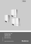
1
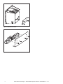
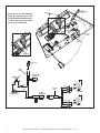
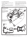
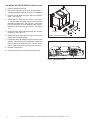
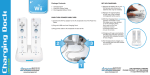
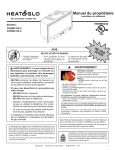
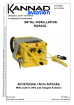
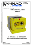
GFK-210 Blower System
- Installation and Operating Instructions -
1.0 INTRODUCTION
The GFK-210 Blower System has been designed to circulate room air through the fireplace to enhance heat output.
The GFK-210 blower system operates on 120 VAC, 60 Hz
power. This is available through a receptacle in the factory
installed power cord assembly. The power cord is located
in the controls compartment of the fireplace.
A variable speed control is provided with the blower system
to provide quiet forced air flow at the desired speeds. A
temperature sensor switch, which automatically turns the
blower ON/OFF, is also provided with this kit.
NOTICE: The variable speed control and temperature
sensor switch are not used with some remote control
systems.
2.0 CHECK CONTENTS OF SHIPPING CARTON
Compare CONTENTS OF CARTON in Figure 1 with the
actual parts received. If any parts are missing or damaged,
contact your dealer before starting installation. Do not install
a damaged blower kit.
This blower is carefully engineered and must be installed
only as specified. If you modify it or any of its components,
you may cause a fire hazard and will void the WARRANTY.
In addition, such action may void the coverage provided
by the owner's home insurance.
CAUTION: All wiring should be done by a qualified electrician and shall be in compliance with local codes and with
the National Electric Code ANSI/NFPA NO. 70-current (in
the United States), or with the current CSA C22.1 Canadian
Electric Code (in Canada).
CAUTION! DO NOT connect 110-120 VAC wiring to the
gas control valve of the fireplace.
WARNING! Risk of Shock! Turn electrical power off at
the circuit breaker before beginning this installation.
4.0 INSTALLING THE BLOWER (Metal Inserts)
1. Remove factory-installed blower brackets by removing
four screws. Brackets are only used for the FireBrick
inserts. See Figure 2.
2. Remove appliance from wall.
3. Remove access panel by removing four screws. See
Figure 3.
4. Screw blowers to access panel on rear of insert with
four screws. See Figure 4.
WING
NUT
060-872
BLOWER CORD
2206-068
CONTROL
KNOB
100-512
TEMPERATURE
SENSOR
SWITCH
046-018A
5. Plug the blower cord into the blower receptacle. Connect the white, black, and green spade connectors
from blower cord harness to each blower. See Figure
1 and Figure 6.
6. Bundle and zip tie any wires to keep them from contacting the fan blades. See Figure 6, Detail A.
7. Reinstall access panel.
NOTE: Install the blower using the access panel located on
the back side of the appliance.
CONTROL
NUT
060-814
VARIABLE SPEED CONTROL
2206-800
Figure 1
3.0 INSTALLATION PRECAUTIONS
The GFK-210 Blower Kit is tested and safe when installed in
accordance with this installation manual. It is your responsibility to read all instructions before starting installation and to
follow these instructions carefully during installation to assure
maximum benefit from, and safe operation of, the blower.
Figure 2 Remove Blower Brackets
Hearth & Home Technologies • GFK-210 Blower System Instructions 2206-938 Rev. H • 7/11
1
Figure 3 Remove Access Cover
Figure 4 Attach Blowers to Access Cover
2
Hearth & Home Technologies • GFK-210 Blower System Instructions 2206-938 Rev. H • 7/11
5.0 INSTALLING THE VARIABLE SPEED
CONTROL AND TEMPERATURE SENSOR SWITCH
If using a remote control system that utilizes a blower
(fan) control, disregard steps 1-3 and follow remote control installation instructions.
NOTICE! The sensor switch and rheostat are not used
if the blower is controlled with the RC300 remote control.
1. Remove the knob and locknut from the variable speed
control. Slide the variable speed control behind the
control panel. With the stem sticking out of the prepunched hole, attach the locknut tightly and reattach
the knob on the stem. See Figure 4. Turn the speed
control switch to the "ON" position.
2. Slide the temperature sensor switch onto the blower
stud located on the bottom of the combustion box. See
Figure 3. Secure the temperature sensor switch with
the wing nut provided.
NOTICE: The blower stud is located on the bottom of the
combustion box. See Figure 5.
NOTICE: The temperature sensor switch must be installed
so that the sensor switch is facing the combustion box
surface. See Detail A of Figure 5.
3. Connect the variable speed control and the temperature
sensor switch to the power cord. See Figure 6.
4. Gather the loose wires underneath the appliance and
use the zip ties to restrain them and keep them away
from the blower wheel (fan blades). See Figure 6,
Detail A.
5. Turn the 110-120 VAC service "ON" at the circuit
breaker.
6.0 RECOMMENDED OPERATING PROCEDURES WHEN VARIABLE SPEED CONTROL AND
TEMPERATURE SENSOR SWITCH ARE USED
Ignite the fire in the fireplace with the variable speed control
switch in an "ON" position. The fan will automatically turn
on when the temperature sensor switch closes at approximately 110O F. Heated air will be delivered at the outlet
grille. The fan will continue to operate after the fireplace
is turned OFF until the temperature sensor switch opens.
NOTICE! During operation, ensure that all wiring is
kept away from the blower wheel (fan blades).
Various conditions (such as fireplace model, type of fireplace installation, outside air temperature vs. inside air
temperature) can contribute to the length of the time the
blower remains on after the fireplace is turned OFF. The
blower can be turned off manually with the speed control
switch.
WARNING! Risk of Injury! DO NOT contact the blower
wheel (fan blades) during operation.
7.0 MAINTENANCE
Periodically check the fireplace and remove any dust, dirt
or obstructions.
8.0 REPLACEMENT PARTS AND CUSTOMER
SERVICE
Replacement parts and service may be obtained through
your dealer.
Hardware Bag: SRV107-570A
VARIABLE
SPEED
CONTROL
TEMPERATURE
SENSOR
SWITCH
BLOWER
STUD
DETAIL A
COMBUSTION BOX SURFACE
BLOWER STUD
TEMPERATURE SENSOR SWITCH
Figure 5
Hearth & Home Technologies • GFK-210 Blower System Instructions 2206-938 Rev. H • 7/11
3
PLUG
120V EXISTING
OUTLET
BLOWER
NOTE: IF ANY OF THE ORIGINAL
WIRE AS SUPPLIED WITH THE
APPLIANCE MUST BE REPLACED,
IT MUST BE REPLACED WITH
TYPE 1050 C RATED WIRE.
DETAIL A
POWER CORD
BLOWER TEMPERATURE
SENSOR
CORD
SWITCH
TO VALVE BRACKET
(GROUND)
GRN
DETAIL A
CONTROL
PANEL
VARIABLE
SPEED
CONTROL
(RHEOSTAT)
ORG
TO VALVE
BRN
BLACK
RED
ZIP TIES
PLUG INTO 120V
EXISTING OUTLET
POWER
CORD
DC REGULATOR
RECEPTACLE
VARIABLE SPEED
CONTROL
BLK
BLK
BLK
WHT
BLOWER
CORD
BLK
GRN
BLK
BLK
GRN
BLK
BLOWERS
TEMPERATURE
SENSOR SWITCH
BLOWER
RECEPTACLE
BLK
GRN
WHT
BLK
GRN
BLK
Figure 6. Fan Wiring Diagram - Metal Insert Without RC200/RC300
4
Hearth & Home Technologies • GFK-210 Blower System Instructions 2206-938 Rev. H • 7/11
9.0 Fan Wiring with Remote
2. Plug two cord assembly spade connectors together.
This appliance may be used with an RC200 or RC300
remote control. See Figure 7.
3. Unplug fan cord assembly from standard cord assembly.
1. Remove cord assembly spades from rheostat and
sensor switch.
NOTICE: Fan speed and operation are controlled by the
remote control. The sensor switch and rheostat are no
longer needed.
NOTE: IF ANY OF THE ORIGINAL
WIRE AS SUPPLIED WITH THE
APPLIANCE MUST BE REPLACED,
IT MUST BE REPLACED WITH TYPE
1050 C RATED WIRE.
4. Install fuse wire assembly in series between the black
lead wires of the fan cord and black lead wire on each
blower. See Figure 7.
5. Plug fan cord assembly into AUX300 module.
6. Plug AUX300 module into the standard cord assembly.
PLUG
120V EXISTING
OUTLET
BLOWER
STEP 5
NOTE: USE ZIP TIES TO RESTRAIN
THE LOOSE WIRES UNDERNEATH
THE APPLIANCE AND KEEP THEM
AWAY FROM THE BLOWER WHEEL
(FAN BLADES).
STEPS
1&2
STEPS
3&5
SENSOR SWITCH
WHT (2)
GRN (2)
BLK (2)
BLK (2)
GRN (2)
BLK (2)
SPEED CONTROL
(RHEOSTAT)
NOTE: SENSOR SWITCH AND
RHEOSTAT SPEED CONTROL MUST
BE REMOVED FROM CIRCUIT IF
SYSTEM IS CONTROLLED WITH
RC200/300 REMOTE.
PLUG INTO 120V
EXISTING OUTLET
DC REGULATOR
RECEPTICLE
WHT
GRN
BLK
GRN
BLK
BLK
AUX 300 MODULE
TO CONTROL
MODULE
BLOWERS
FUSE WIRE
ASSEMBLY
FAN
BLK
BLK
BLK
GRN
WHT
FUSE WIRE
ASSEMBLY
BLK
GRN
BLK
BLOWER
RECEPTICLE
Figure 7. Fan Wiring Diagram - Metal Insert with RC200/RC300 Remote
Hearth & Home Technologies • GFK-210 Blower System Instructions 2206-938 Rev. H • 7/11
5
10.0 INSTALLING THE BLOWER (FireBrick Inserts)
1. Remove appliance from wall.
2. Disconnect power by shutting off circuit breaker or
unplugging appliance power cord from its receptacle.
3. Remove access panel from lower rear of the fireplace
insert. See Figure 8.
4. Attach blower to base with two screws. See Figure
9. Connect white and green wires from blower wire
assembly to each blower. See Figure 9. Connect the
fuse wire assembly in series between black wires of
blower wire assembly and each blower. See Figure
10.
5. Insert plug from blower cable assembly into AUX300
receptacle. See Figure 10.
6. Bundle and zip tie loose wires to keep them from contacting blower impeller blades
BLOWER
ACCESS PANEL
POWER CORD
Figure 8. Remove Access Panel
7. Position the right and left blower assembly into the rear
opening. Take care to ensure that blower housing or its
motor is clear of any adjacent metal. This will ensure
that no undue noise occurs during blower operation.
8. Reinstall access panel.
9. Reconnect power to the insert and install into wall.
Figure 9. Attach Blower to Base
6
Hearth & Home Technologies • GFK-210 Blower System Instructions 2206-938 Rev. H • 7/11
Note: if any of the original wire as
supplied with the appliance must
be replaced, it must be replaced
with type 105 °C rated wire.
PLUG TO
EXISTING
OUTLET
BLOWERS
Note: use zip ties to restrain
the loose wires underneath the
appliance and keep them away
from the blower wheel (fan blades).
PLUG INTO 120V
EXISTING OUTLET
BROWN
RED
BLACK
DC REGULATOR
RECEPTACLE
GROUND (TO VALVE BRACKET)
GREEN (TO VALVE)
ORANGE (TO VALVE)
BLK
WHT
BLK
GRN
GRN
BLK
BLOWER
RECEPTACLE
BLK
BLOWERS
FUSE WIRE
ASSEMBLY
BLK
BLK
FUSE WIRE
ASSEMBLY
GRN
WHT
BLK
GRN
BLK
Figure 10. Fan Wiring Diagram - FireBrick Inserts
Please contact your Hearth & Home Technologies dealer
with any questions or concerns.
For the location of your nearest
Hearth & Home Technologies dealer,
please visit www.fireside.com.
Hearth & Home Technologies Inc.
7571 215th Street West, Lakeville, MN 55044
www.fireside.com
Hearth & Home Technologies • GFK-210 Blower System Instructions 2206-938 Rev. H • 7/11
7