1
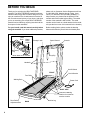
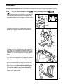
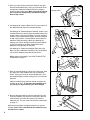
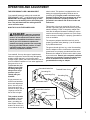
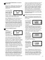
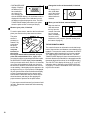
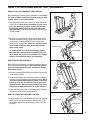
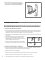
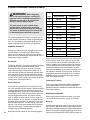
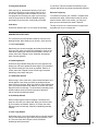
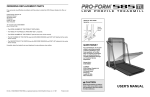
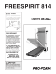
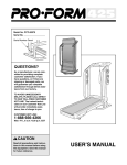
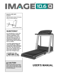
Model No. HRTL20001
Serial No.
Serial Number Decal
QUESTIONS?
As a manufacturer, we are
committed to providing complete customer satisfaction. If
you have questions, or find that
there are missing or damaged
parts, we will guarantee complete satisfaction through direct
assistance from our
factory.
TO AVOID UNNECESSARY DELAYS, PLEASE CALL DIRECT
TO OUR TOLL-FREE CUSTOMER
HOT LINE. The trained technicians on our customer hot line
will provide immediate assistance, free of charge to you.
CUSTOMER HOT LINE:
1-800-999-3756
Mon.–Fri., 6 a.m.– 6 p.m. MST
CAUTION
Read all precautions and instructions in this manual before using
this equipment. Save this
manual for future reference.
USER'S MANUAL
TABLE OF CONTENTS
IMPORTANT PRECAUTIONS . . . . . . . . . . . . . . . . . . . . . . . . . . . . . . . . . . . . . . . . . . . . . . . . . . . . . . . . . . . . . . . . .3
BEFORE YOU BEGIN . . . . . . . . . . . . . . . . . . . . . . . . . . . . . . . . . . . . . . . . . . . . . . . . . . . . . . . . . . . . . . . . . . . . . . .4
ASSEMBLY . . . . . . . . . . . . . . . . . . . . . . . . . . . . . . . . . . . . . . . . . . . . . . . . . . . . . . . . . . . . . . . . . . . . . . . . . . . . . . .5
OPERATION AND ADJUSTMENT . . . . . . . . . . . . . . . . . . . . . . . . . . . . . . . . . . . . . . . . . . . . . . . . . . . . . . . . . . . . .7
HOW TO FOLD AND MOVE THE TREADMILL . . . . . . . . . . . . . . . . . . . . . . . . . . . . . . . . . . . . . . . . . . . . . . . . . .11
TROUBLE-SHOOTING . . . . . . . . . . . . . . . . . . . . . . . . . . . . . . . . . . . . . . . . . . . . . . . . . . . . . . . . . . . . . . . . . . . . .12
CONDITIONING GUIDELINES . . . . . . . . . . . . . . . . . . . . . . . . . . . . . . . . . . . . . . . . . . . . . . . . . . . . . . . . . . . . . . .14
ORDERING REPLACEMENT PARTS . . . . . . . . . . . . . . . . . . . . . . . . . . . . . . . . . . . . . . . . . . . . . . . . . .Back Cover
LIMITED WARRANTY . . . . . . . . . . . . . . . . . . . . . . . . . . . . . . . . . . . . . . . . . . . . . . . . . . . . . . . . . . . . . . .Back Cover
Note: An EXPLODED DRAWING and a PART LIST are attached to the center of this manual. Save the
EXPLODED DRAWING and PART LIST for future reference.
WARNING:
Before beginning this or any exercise program, consult your physician. This
is especially important for persons over the age of 35 or persons with pre-existing health problems.
Read all instructions before using. HEALTHRIDER assumes no responsibility for personal injury or
property damage sustained by or through the use of this product.
2
IMPORTANT PRECAUTIONS
WARNING:
To reduce the risk of burns, fire, electric shock, or injury to persons, read the
following important precautions and information before operating the treadmill.
1. It is the responsibility of the owner to ensure
that all users of this treadmill are adequately
informed of all warnings and precautions.
2. Use the treadmill only as described in this
manual.
3. Place the treadmill on a level surface, with
eight feet of clearance behind it. Do not place
the treadmill on any surface that blocks air
openings. To protect the floor or carpet from
damage, place a mat under the treadmill.
4. Keep the treadmill indoors, away from moisture and dust. Do not place the treadmill in a
garage or covered patio, or near water.
5. Do not operate the treadmill where aerosol
products are used or where oxygen is being
administered.
6. Keep small children and pets away from the
treadmill at all times.
7. The treadmill should be used only by persons weighing 250 pounds or less. Do not
allow more than one person on the treadmill
at a time.
8. When connecting the power cord (see HOW
TO PLUG IN THE POWER CORD on page 7),
plug the power cord into a surge protector
(not included) and plug the surge protector
into a grounded circuit capable of carrying
15 or more amps. No other appliance should
be on the same circuit.
9. Use only a UL-listed surge protector, rated at
15 amps, with a 14-gauge cord of five feet or
less in length. Do not use an extension cord.
10. Keep the power cord and the surge protector
away from heated surfaces.
11. Never move the walking belt while the power
is turned off. Do not operate the treadmill if
the power cord or plug is damaged, or if the
treadmill is not working properly. (See BEFORE YOU BEGIN on page 4 if the treadmill is
not working properly.)
12. Wear appropriate clothing when using the
treadmill; do not wear loose clothing that
could become caught in the treadmill. Athletic
support clothes are recommended for both
men and women. Always wear athletic shoes;
never use the treadmill with bare feet, wearing only stockings, or in sandals.
13. Never start the treadmill while you are standing on the walking belt. Always hold the
handrails while using the treadmill.
14. The treadmill is capable of high speeds.
Adjust the speed in small increments to
avoid sudden jumps in speed.
15. To reduce the possibility of the treadmill
overheating, do not operate the treadmill
continuously for longer than 1 hour.
16. The pulse sensor is not a medical device.
Various factors, including the user's movement, may affect the accuracy of heart rate
readings. The pulse sensor is intended only
as an exercise aid in determining heart rate
trends in general.
17. Never leave the treadmill unattended while it
is running. Always remove the key and move
the on/off switch to the “off” position when
the treadmill is not in use. (See the drawing
on page 4 for the location of the on/off
switch.)
18. You must be able to safely lift 45 pounds (20
kg) to raise, lower, or move the treadmill.
19. When storing or moving the treadmill, make
sure that the storage latch is fully closed.
20. Never insert any object into any opening.
21. Inspect and tighten all parts of the treadmill
every three months.
22. Always unplug the power cord before performing the maintenance and adjustment
procedures described in this manual. Never
remove the motor hood unless instructed to
do so by an authorized service representative. Servicing other than the procedures in
this manual should be performed by an authorized service representative only.
SAVE THESE INSTRUCTIONS
3
BEFORE YOU BEGIN
Thank you for selecting the HEALTHSTRIDER
treadmill. The HEALTHSTRIDER treadmill combines
advanced technology with innovative design to let you
enjoy an excellent form of cardiovascular exercise in
the convenience and privacy of your home. And when
you’re not exercising, the unique HEALTHSTRIDER
treadmill can be folded up, requiring less than half the
floor space of other treadmills.
please call our Customer Service Department toll-free
at 1-800-999-3756, Monday through Friday, 6 a.m.
until 6 p.m. Mountain Time (excluding holidays). To
help us assist you, please note the product model
number and serial number before calling. The model
number of the treadmill is HRTL20001. The serial
number can be found on a decal attached to the treadmill (see the front cover of this manual for the location).
For your benefit, read this manual carefully before
using the treadmill. If you have additional questions,
Before reading further, please review the drawing
below and familiarize yourself with the labeled parts.
Towel
Rack
Water
Bottle
Holder*
Storage Latch
Speed Control
Console
Accessory
Tray
* Water Bottle is not included.
Key/Clip
Handrails
On/Off Switch
FRONT
Circuit Breaker
Foot Rails
Walking Belt
Power Cord
RIGHT SIDE
Cushioned Walking
Platform for maximum
exercise comfort
Rear Roller
Adjustment Bolt
4
BACK
Incline Leg
ASSEMBLY
Assembly requires two people. Set the treadmill in a cleared area and remove all packing materials. Do not dispose of the packing materials until assembly is completed. Tools required for assembly: The included allen
wrench
and your phillips screwdriver
and two adjustable wrenches
.
1. Attach six Base Pads (73) to the bottom of the Base (75)
in the indicated locations (see the inset drawing). Note:
One additional Base Pad will be used in assembly step 6,
and one extra Base Pad is included.
73
1
73
73
75
73
2. Firmly hold the Uprights (11, 58) as shown. Raise the
Uprights until the Base (75) and the front Wheels (74)
are resting on the floor.
2
11
58
74
75
3. Loosen the Crossbar Bolts (2) in the ends of the Console
Crossbar (17). Pivot the Console (6) to the angle shown.
Look under the Left and Right Crossbar Brackets (4, 51)
and find the two small holes in each end of the Console
Crossbar (17). Tighten Crossbar Screws (9) into all four
holes.
3
6
2
4
9
Rotate the Console (6) upward until it stops. Using the
7/32” end of the Allen Wrench (56), tighten the Crossbar
Bolts (2) in the ends of the Console Crossbar (17).
2
17
51
9
4. Next, the treadmill should be raised to the storage position. Hold the treadmill with your hands in the locations
shown at the right. To decrease the possibility of injury, bend your legs and keep your back straight. As
you raise the treadmill, make sure to lift with your
legs rather than your back. Raise the treadmill about
halfway to the vertical position.
56
4
5
5. Move your right hand to the position shown at the right,
and hold the treadmill firmly. Using your left hand, lift the
storage latch. Raise the treadmill until the locking pin
snaps into the storage latch. Make sure that the locking
pin is inside the storage latch, and that the storage
latch is fully closed.
6. See drawing 6B. Attach a Base Pad (73) to the bottom of
the Stabilizer Plate (88) in the indicated location.
5
Storage Latch
Locking Pin
6B
6A
88
4
See drawing 6A. Stand behind the treadmill. Hold the Left
Crossbar Bracket (4) and the Right Crossbar Bracket (not
shown). Place one foot on the Base (75) in the indicated
location.Tip the treadmill back slightly. While the treadmill
is held in this position, a second person should slide the
Stabilizer Plate (88) onto the Base (see drawing 6C).
Keeping your foot on the Base, carefully tip the treadmill
up until it is resting on the Base. Make sure that the
Stabilizer Plate (88) stays on the Base.
73
88
See drawing 6C. Attach the Stabilizer Plate (88) to the
Base (75) with a Stabilizer Plate Bolt (105), two Washers
(97), and the Stabilizer Plate Nut (95) as shown.
75
Before moving the treadmill, see HOW TO MOVE THE
TREADMILL on page 11.
6C
95
97
105
75
7. Refer to assembly drawing 5 at the top of this page. Hold
the upper end of the treadmill with your right hand as
shown. Using your left hand, lift the storage latch. Pivot
the treadmill slightly until the locking pin is out of the storage latch.
7
Hold the treadmill firmly with both hands, and lower the
treadmill to the floor. To decrease the possibility of injury, bend your legs and keep your back straight.
8. Remove the paper backing from the Adhesive Clip (44).
Press the Adhesive Clip onto the Frame (84) in the indicated location. Press the Allen Wrench (57) into the
Adhesive Clip. The use of the Allen Wrench is described
on page 13.
Make sure that all parts are tightened before you use the
treadmill. Note: Place a mat beneath the treadmill to protect the floor or carpet.
6
8
44
57
84
88
OPERATION AND ADJUSTMENT
THE PERFORMANT LUBETM WALKING BELT
Your treadmill features a walking belt coated with
PERFORMANT LUBETM, a high-performance lubricant.
IMPORTANT: Never apply silicone spray or other
substances to the walking belt or the walking platform. They will deteriorate the walking belt and
cause excessive wear.
HOW TO PLUG IN THE POWER CORD
DANGER:
Improper connection
of the equipment-grounding conductor can
result in an increased risk of electric shock.
Check with a qualified electrician or serviceman if you are in doubt as to whether the
product is properly grounded. Do not modify
the plug provided with the product—if it will
not fit the outlet, have a proper outlet installed by a qualified electrician.
electric shock. This product is equipped with a cord
having an equipment-grounding conductor and a
grounding plug. Plug the power cord into a surge
protector, and plug the surge protector into an appropriate outlet that is properly installed and
grounded in accordance with all local codes and
ordinances.
This product is for use on a nominal 120-volt circuit,
and has a grounding plug that looks like the plug illustrated in drawing 1 below. A temporary adapter that
looks like the adapter illustrated in drawing 2 may be
used to connect the surge protector to a 2-pole receptacle as shown in drawing 2 if a properly grounded outlet is not available.
The temporary adapter should be used only until a
properly grounded outlet (drawing 1) can be installed
by a qualified electrician.
The green-colored rigid ear, lug, or the like extending
from the adapter must be connected to a permanent
ground such as a properly grounded outlet box cover.
Whenever the adapter is used it must be held in place
by a metal screw. Some 2-pole receptacle outlet box
covers are not grounded. Contact a qualified electrician to determine if the outlet box cover is
grounded before using an adapter.
Your treadmill, like any other type of sophisticated
electronic equipment, can be seriously damaged by
sudden voltage changes in your home’s power.
Voltage surges, spikes, and noise interference can result from weather conditions or from other appliances
being turned on or off.
To decrease the pos1
sibility of your treadGrounded Outlet Box
mill being damaged,
Treadmill Power Cord
always use a surge
Grounding Pin
protector (not included) with your
Grounding Plug
Grounding Plug
treadmill.
Surge protectors are
sold at most hardware
stores and department
stores. Use only a ULlisted surge protector,
rated at 15 amps, with a
14-gauge cord of five
feet or less in length.
This product must be
grounded. If it should
malfunction or break
down, grounding provides a path of least resistance for electric current to reduce the risk of
Grounding Pin
Grounded Outlet
2
Grounded Outlet Box
Adapter
Grounding Pin
Grounding Plug
Surge Protector
Lug
Metal Screw
7
DIAGRAM OF THE CONSOLE
Mode Indicators
Warm
-up
Performance
FAST
CAL. / FAT CAL.
Cool
-down
TIME
A
SPEED PROFILES
FAT
B
Aerobic
C
DIST. / PULSE
SPEED
D
Fat Burn
KPH
E
F
Warm-Up &
Cool-Down
30 28 26 24 22 20 18 16 14 12 10 8
6
4
2
INCLINE
Mins.
MANUAL
SLOW
ON
THUMB PULSE
OFF
1
INSERT
KEY
RESET/
PAUSE
2
3
RESET /
SET SPEED
Key
SELECT
MODE
4
START
/ STOP
Speed Control
Note: If there is a thin sheet
of clear plastic on the face of
the console, remove it.
Clip
CAUTION:
Before operating the
console, read the following precautions.
• Do not stand on the walking belt when turning on the power.
• Always wear the clip (see the drawing above)
while operating the treadmill.
If the key is in the console, remove it. Make sure that
the power cord is properly plugged in. (See HOW TO
PLUG IN THE POWER CORD on page 7.)
Next, step onto the foot rails of the treadmill. Find the
clip attached to the key (see the drawing above), and
slide the clip onto the waistband of your clothing.
Follow the steps below to operate the console:
1
• Adjust the speed in small increments.
• To reduce the possibility of electric shock, keep
the console dry. Avoid spilling liquids on the
console, and use only a sealed water bottle.
Insert the key fully into the power switch.
The four displays
and the green MANUAL mode indicator
will light.
• The training zones marked beside the speed
control are general guidelines only. See
CONDITIONING GUIDELINES on page 14.
2
ON
OFF
1
INSERT
KEY
Reset the speed control and select a speed
setting.
STEP-BY-STEP CONSOLE OPERATION
The treadmill console features a manual mode and six
preset workout programs. In the manual mode, the
speed of the walking belt can be changed with the electronic speed control. When one of the workout programs
is selected, the console will automatically control the
speed as it guides you through an effective workout.
8
Before operating the
console, make sure
that the on/off switch
near the power cord
is in the “on” position.
“On”
Position
OFF
ON
Slide the speed control down to
the "RESET" position. Note:
Each time the walking belt is
stopped, the speed control
must be moved to the
“RESET” position before the
walking belt can be restarted.
Next, slide the speed control upward to select a speed setting.
Note: If the key was just inserted, the walking belt will
not begin to move yet.
mance
FAST
c
rn
Up &
own
SLOW
ESET/
AUSE
2
RESET /
SET SPEED
3
Press the SELECT MODE button to select the
desired mode.
control is set, the greater the speed range will be and
the faster the walking belt will move during the program. If the program is too easy or too difficult, adjust
the speed control to select a new maximum speed
setting. To stop the program temporarily, slide the
speed control to the “RESET” position. The SPEED
display will begin to flash. To restart the program,
slide the speed control up to the desired position. To
end the program before the program is completed,
press the START/STOP button. If you select a different program while a program is running, the walking
belt will slow to a stop.
When the key is inserted, the console will be in the
MANUAL mode. The MANUAL mode can also be
selected by repeatedly pressing the SELECT
MODE button.
If you want to select
one of the six preset
programs, press the
SELECT
SELECT MODE butMODE
ton. The red PROGRAM A indicator
will light. To select PROGRAM B, C, D, E, or F, repeatedly press the SELECT MODE button.
3
4
Note: PROGRAMS A, B, and C are twenty-minute
programs; PROGRAMS D, E, and F are thirtyminute programs. The speed profiles in the center
of the console show how the speed of the walking
belt will change during the programs. During PROGRAM A, for example, the speed will gradually increase during the first ten minutes, and then gradually decrease during the last ten minutes. Each program will begin with a two-minute warm-up period,
and end with a two-minute cool-down period.
4
Press the START/STOP button.
After the
START/STOP button is pressed, the
ECT
START
walking belt will
E
/ STOP
begin to move. Hold
the handrails and
carefully begin walking on the walking belt.
4
If the console is in the manual mode, change the
speed of the walking belt as desired by sliding
the speed control. To stop the walking belt, slide the
speed control to the “RESET” position. The SPEED
display will begin to flash. To restart the walking
belt, slide the speed control upward. Note: The
walking belt can also be stopped by pressing the
START/ STOP button; however, this will reset the
displays. To restart the walking belt, slide the speed
control to the “RESET” position, slide it upward, and
then press the START/STOP button.
|f one of the preset programs is selected, the speed
of the walking belt will change automatically during
the program as shown by the speed profiles in the
center of the console. The time remaining in the program will be shown in the TIME display. When the
program is completed, the walking belt will slow to a
stop. Note: The position of the speed control determines both the speed range and the maximum
speed setting for the program. The higher the speed
5
Follow your progress with the monitor displays.
The four monitor displays provide instant exercise
feedback. The displays are explained below and on
the next page.
• CAL/FAT CAL disCAL. / FAT CAL.
TIME
play—Displays the
FAT
numbers of both
Calories and Fat
Calories you have
burned (see
BURNING FAT on page 14). Every seven seconds, the display will change from one number to
the other. The FAT indicator will light when the
number of Fat Calories is shown. Note: The actual
number of Calories you have burned may differ
slightly from the number shown if the speed or incline is near the lowest or highest setting.
• TIME display—
TIME
When the console
is in the manual
mode, the elapsed
time will be shown.
When one of the
preset programs is selected, the time remaining in
the program will be displayed.
• SPEED display—
SPEED
Displays the speed
of the walking belt,
KPH
in miles per hour or
kilometers per hour.
The KPH indicator
will light when the speed is displayed in kilometers
per hour.
Note: To change the unit of measurement, hold
down the START/STOP button while inserting the
key into the console. An “E” (for English system—
miles per hour) or “M” (for Metric system—kilometers per hour) will appear in the CAL/FAT CAL display. Press the SELECT MODE button to change
the setting. Remove and then reinsert the key.
9
• DISTANCE/PULSE
DIST. / PULSE
display—Displays
the distance you
have walked or
run. Note: If the
KPH indicator beside the SPEED display is lit, the distance will be
displayed in kilometers. If the indicator is not lit,
the distance will be displayed in miles. The DISTANCE/PULSE display also shows your pulse
when the pulse sensor is used (see step 6).
6
Measure your pulse, if desired.
To use the pulse sensor, stand on the foot rails and
place your thumb on the pulse sensor as shown.
The pulse
sensor is
Pulse
pressure-acSensor
tivated. Fully
press down
the pulse
sensor. Do
not press
too hard, or
the circulation in your thumb will be restricted, and your
pulse will not be detected. Next, slightly raise
your thumb until the heart-shaped indicator beside
the DISTANCE/ PULSE display flashes steadily.
Hold your thumb at this level. After 5 to 10 seconds,
your pulse will be displayed. Hold your thumb on
the sensor for another 15 seconds for the most accurate reading. If the displayed pulse appears to be
too high or too low, or if your pulse is not displayed,
lift your thumb off the sensor and allow the display
to reset. Press down again on the sensor as described above. Make sure that your thumb is positioned as shown, and that you are applying the
proper amount of pressure to the pulse sensor.
Try the sensor several times until you become familiar with it. Remember to stand still while measuring
your pulse.
10
7
Change the incline of the treadmill, if desired.
To change the incline, hold down
one of the incline
buttons until the
desired incline is
reached.
8
L
INCLINE
When you are finished, remove the key.
1 KEY
Step onto the foot
rails and remove
the key from the
console. Store the
key in a secure
place. In addition,
move the on/off
switch to the “off” position. (See the drawing near
the bottom of page 8.)
THE INFORMATION MODE
The console features an information mode that keeps
track of the total time and distance accumulated on the
treadmill. To access this mode, hold down the START/
STOP button while inserting the key into the console.
The TIME display will show the total time. The DISTANCE/PULSE display will show the total distance (if
the total distance exceeds 999, the thousands and ten
thousands digits will be shown in the SPEED display).
The CAL/FAT CAL display will show an “E” or an “M,”
indicating miles or kilometers (see SPEED DISPLAY
on page 9). To exit the information mode, remove the
key from the console.
HOW TO FOLD AND MOVE THE TREADMILL
HOW TO FOLD THE TREADMILL FOR STORAGE
Before folding the treadmill, unplug the power cord. Caution:
You must be able to safely lift 45 pounds (20 kg) in order
to raise, lower, or move the treadmill.
1. Hold the treadmill with your hands in the locations shown
at the right. To decrease the possibility of injury, bend
your legs and keep your back straight. As you raise
the treadmill, make sure to lift with your legs rather
than your back. Raise the treadmill about halfway to the
vertical position.
2. Move your right hand to the position shown at the right,
and hold the treadmill firmly. Using your left hand, lift the
storage latch. Raise the treadmill until the locking pin
snaps into the storage latch. Make sure that the locking
pin is inside the storage latch, and that the storage
latch is fully closed.
Storage Latch
Locking Pin
To protect the floor or carpet from damage, place a
mat under the treadmill. Keep the treadmill out of direct sunlight. Do not leave the treadmill in the storage
position in temperatures above 85° Fahrenheit.
HOW TO MOVE THE TREADMILL
Crossbar
Bracket
Before moving the treadmill, convert the treadmill to the storage position as described above. Make sure that the locking pin is inside the storage latch, and that the storage
latch is fully closed.
1. Hold one crossbar bracket with each hand. Place one foot
on the base as shown.
2. Tilt the treadmill back until it rolls freely on the front wheels.
Carefully move the treadmill to the desired location. Never
move the treadmill without tipping it back, or the base
pads may come off. To reduce the risk of injury, use
extreme caution while moving the treadmill. Do not attempt to move the treadmill over an uneven surface.
Base
3. Place one foot on the base, and carefully lower the treadmill until it is resting in the storage position.
Front Wheels
HOW TO LOWER THE TREADMILL FOR USE
1. Hold the upper end of the treadmill with your right hand as
shown. Using your left hand, lift the storage latch. Pivot
the treadmill slightly until the locking pin is out of the storage latch.
Storage Latch
Locking Pin
11
2. Hold the treadmill firmly with both hands, and lower the
treadmill to the floor. To decrease the possibility of injury, bend your legs and keep your back straight.
TROUBLE-SHOOTING
Most treadmill problems can be solved by following the steps below. Find the symptom that applies, and
follow the steps listed. If further assistance is needed, please call our Customer Service Department tollfree at 1-800-999-3756, Monday through Friday, 6 a.m. until 6 p.m. Mountain Time (excluding holidays).
1. SYMPTOM: THE POWER DOES NOT TURN ON
a. Make sure that the power cord is plugged into a surge protector, and that the surge protector is plugged into
a properly grounded outlet. (See HOW TO PLUG IN THE POWER CORD on page 7.) Use only a UL-listed
surge protector, rated at 15 amps, with a 14-gauge cord of five feet or less in length.
b. After the power cord has been plugged in, make sure that the key is fully inserted into the console. (See step
1 on page 8.)
c. Check the circuit breaker located on the treadmill near the
power cord. If the switch protrudes as shown, the circuit
breaker has tripped. To reset the circuit breaker, wait for five
minutes and then press the switch back in.
Tripped
Reset
Tripped
d. Check the on/off switch located at the front of the treadmill
near the power cord. The switch must be in the “on” position.
“On”
Position
Reset
OFF
ON
2. SYMPTOM: THE POWER TURNS OFF DURING USE
a. Check the circuit breaker located on the treadmill frame near the power cord (see 1. c. above). If the circuit
breaker has tripped, wait for five minutes and then press the switch back in.
b. Make sure that the power cord is plugged in.
c. Remove the key from the console. Reinsert the key fully into the console. (See step 1 on page 8.)
d. Check to make sure that the on/off switch is in the “on” position. (See 1. d. above.)
12
e. If the treadmill still will not run, please call our Customer Service Department, toll-free.
3. SYMPTOM: THE WALKING BELT SLOWS WHEN WALKED ON
a. Use only a UL-listed surge protector, rated at 15 amps, with a 14-gauge cord of five feet or less in length.
b. If the walking belt still slows when walked on, please call our Customer Service Department, toll-free.
4. SYMPTOM: THE WALKING BELT IS OFF-CENTER WHEN WALKED ON
a. If the walking belt has shifted to the left, first remove the key and
UNPLUG THE POWER CORD. Using the 3/16” end of the allen
wrench, turn the left rear roller adjustment bolt clockwise 1/4 of a
turn. Plug in the power cord, insert the key and run the treadmill
for a few minutes. Repeat until the walking belt is centered.
b. If the walking belt has shifted to the right, first remove the key
and UNPLUG THE POWER CORD. Using the 3/16” end of the
allen wrench, turn the left rear roller adjustment bolt counterclockwise 1/4 of a turn. Plug in the power cord, insert the key
and run the treadmill for a few minutes. Repeat until the walking
belt is centered.
a
b
5. SYMPTOM: THE TREADMILL SITS UNEVENLY ON THE FLOOR
a. Make sure that the two base pads and the stabilizer pad are attached to the treadmill (see assembly steps 1
and 6 on pages 5 and 6).
13
CONDITIONING GUIDELINES
WARNING: Before beginning
this or any exercise program, consult your
physician. This is especially important for individuals over the age of 35 or individuals
with pre-existing health problems.
AGE
Unconditioned
Conditioned
20
138-167
133-162
25
136-166
132-160
The pulse sensor is not a medical device.
Various factors, including your movement,
may affect the accuracy of heart rate readings.
The sensor is intended only as an exercise aid
in determining heart rate trends in general.
30
135-164
130-158
35
134-162
129-156
40
132-161
127-155
45
131-159
125-153
50
129-156
124-150
The following guidelines will help you to plan your exercise program. Remember—these are general guidelines. For more detailed information about exercise,
obtain a reputable book or consult your physician.
55
127-155
122-149
60
126-153
121-147
65
125-151
119-145
EXERCISE INTENSITY
70
123-150
118-144
75
122-147
117-142
80
120-146
115-140
85
118-144
114-139
Whether you want to burn fat, strengthen your cardiovascular system, or increase your athletic performance, you can tailor your exercise to your specific
goals. The key to achieving the desired results is to exercise with the proper intensity.
Burning Fat
To burn fat effectively, you must exercise at a relatively
low intensity level for a sustained period of time.
During the first few minutes of exercise, your body
uses easily accessible carbohydrate calories for energy. Only after the first few minutes of exercise does
your body begin to use stored fat calories for energy.
If your goal is to burn fat, set the speed control on the
console to FAT BURN to help you maintain the proper
intensity level. (See pages 8 and 9.)
Aerobic Exercise
If your goal is to strengthen your cardiovascular system, your exercise must be “aerobic.” Aerobic exercise
is activity that requires large amounts of oxygen for
prolonged periods of time. This increases the demand
on the heart to pump blood to the muscles, and on the
lungs to oxygenate the blood. The proper intensity
level for aerobic exercise can be found by using your
pulse as a guide. As you exercise, your pulse should
be kept at a level between 70% and 85% of your maximum possible heart rate. This is known as your training zone. You can find your training zone in the table
at the top of this page. Training zones are listed according to age and physical condition.
14
TRAINING ZONE (Beats/Min.)
During the first few months of your exercise program,
keep your pulse near the low end of your training zone
as you exercise. After a few months of regular exercise, your pulse can be gradually increased until it is
near the middle of your training zone as you exercise.
You can measure your pulse using the pulse sensor.
Exercise for about four minutes, and then measure
your pulse immediately. If your pulse is too high or too
low, adjust the intensity of your exercise. It may also
be helpful to set the speed control on the console to
AEROBIC to help you maintain the proper intensity
level. (See pages 8 and 9.)
Performance Training
If your goal is high performance athletic conditioning,
set the speed control on the console to PERFORMANCE to help you maintain the proper intensity level.
(See pages 8 and 9.)
WORKOUT GUIDELINES
Each workout should include three parts: (1) a warmup, (2) training zone exercise, and (3) a cool-down.
Warm-up
Warming up prepares the body for exercise by increasing circulation, delivering more oxygen to the muscles
and raising the body temperature. Begin each workout
with 5 to 10 minutes of stretching and light exercise to
warm up (see SUGGESTED STRETCHES on page 15).
Training Zone Exercise
After warming up, increase the intensity of your exercise until your pulse is in your training zone for 20 to
60 minutes. (During the first few weeks of your exercise program, do not keep your pulse in your training
zone for longer than 20 minutes.) Breathe regularly
and deeply as you exercise—never hold your breath.
to cool down. This will increase the flexibility of your
muscles and will help to prevent post-exercise problems.
Exercise Frequency
To maintain or improve your condition, complete three
workouts each week, with at least one day of rest between workouts. After a few months, you may complete up to five workouts each week if desired.
Cool-down
Finish each workout with 5 to 10 minutes of stretching
The key to success is to make exercise a regular and
enjoyable part of your everyday life.
SUGGESTED STRETCHES
The correct form for several basic stretches is shown in the
drawings below. Move slowly as you stretch—never bounce.
1
1. Toe Touch Stretch
Stand with your knees bent slightly and slowly bend forward
from your hips. Allow your back and shoulders to relax as you
reach down toward your toes as far as possible. Hold for 15
counts, then relax. Repeat 3 times. Stretches: Hamstrings,
back of knees and back.
2
2. Hamstring Stretch
Sit with one leg extended. Bring the sole of the opposite foot
toward you and rest it against the inner thigh of your extended
leg. Reach toward your toes as far as possible. Hold for 15
counts, then relax. Repeat 3 times for both legs. Stretches:
Hamstrings, lower back and groin.
3
3. Calf/Achilles Stretch
With one leg in front of the other, reach forward and place your
hands against a wall. Keep your back leg straight and your
back foot flat on the floor. Bend your front leg, lean forward and
move your hips toward the wall. Hold for 15 counts, then relax.
Repeat 3 times for both legs. To cause further stretching of the
achilles tendons, bend your back leg as well. Stretches:
Calves, achilles tendons and ankles.
4
4. Quadriceps Stretch
With one hand against a wall for balance, reach back and
grasp one foot with your other hand. Bring your heel as close
to your buttocks as possible. Hold for 15 counts, then relax.
Repeat 3 times for both legs. Stretches: Quadriceps and hip
muscles.
5
5. Inner Thigh Stretch
Sit with the soles of your feet together and your knees outward.
Pull your feet toward your groin area as far as possible. Hold
for 15 counts, then relax. Repeat 3 times. Stretches:
Quadriceps and hip muscles.
15
ORDERING REPLACEMENT PARTS
To order replacement parts, call our Customer Service Department toll-free at 1-800-999-3756, Monday through
Friday, 6 a.m. until 6 p.m. Mountain Time (excluding holidays). When ordering parts, please be prepared to give
the following information:
• The MODEL NUMBER OF THE PRODUCT (HRTL20001).
• The NAME OF THE PRODUCT (HEALTHSTRIDER Treadmill).
• The SERIAL NUMBER OF THE PRODUCT (see the front cover of this manual).
• The KEY NUMBER OF THE PART(S) (see the EXPLODED DRAWING and PART LIST attached to the center
of this manual).
• The DESCRIPTION OF THE PART(S) (see the EXPLODED DRAWING and PART LIST attached to the center
of this manual).
If possible, place the treadmill near your telephone for easy reference when calling.
LIMITED WARRANTY
HEALTHRIDER Acquisition Corp., Inc. (HEALTHRIDER), warrants this product to be free from defects in
workmanship and material, under normal use and service conditions, for a period of ninety (90) days
from the date of purchase. This warranty extends only to the original purchaser. HEALTHRIDER’s obligation under this warranty is limited to replacing or repairing, at HEALTHRIDER’s option, the product at
one of its authorized service centers. All products for which warranty claim is made must be received by
HEALTHRIDER at one of its authorized service centers with all freight and other transportation charges
prepaid, accompanied by sufficient proof of purchase. All returns must be pre-authorized by
HEALTHRIDER. This warranty does not extend to any product or damage to a product caused by or attributable to freight damage, abuse, misuse, improper or abnormal usage or repairs not provided by an
HEALTHRIDER authorized service center, to products used for commercial or rental purposes, or to
products used as store display models. No other warranty beyond that specifically set forth above is authorized by HEALTHRIDER.
HEALTHRIDER is not responsible or liable for indirect, special or consequential damages arising out of
or in connection with the use or performance of the product or damages with respect to any economic
loss, loss of property, loss of revenues or profits, loss of enjoyment or use, costs of removal, installation
or other consequential damages of whatsoever nature. Some states do not allow the exclusion or limitation of incidental or consequential damages. Accordingly, the above limitation may not apply to you.
The warranty extended hereunder is in lieu of any and all other warranties and any implied warranties of
merchantability or fitness for a particular purpose is limited in its scope and duration to the terms set
forth herein. Some states do not allow limitations on how long an implied warranty lasts. Accordingly, the
above limitation may not apply to you.
This warranty gives you specific legal rights. You may also have other rights which vary from state to state.
HEALTHRIDER Acquisition Corp., Inc., 1500 S. 1000 W., LOGAN, UT 84321-9813
Part No. 133039 F02855-C R0896A
Printed in USA © 1996 HEALTHRIDER Acquisition Corp., Inc.
REMOVETHIS
THIS EXPLODED
PART LIST/EXPLODED
REMOVE
DRAWING
FROM
THE
MANUAL!
ANDDRAWING
PART LIST
FROM
THE
MANUAL
34
Save this EXPLODED DRAWING and PART LIST for future reference.
Note: Specifications are subject to change without notice. For information about
ordering replacement parts, see the back cover of the User’s Manual.
PART LIST—Model No. HRTL20001
Key No. Qty.
1
2
3
4*
5
6*
7
8
9
10
11
12
13
14
15
16
17
18
19*
20
21
22
23
24
25
26
27
28
29
30
31
32
33
34
35
36
37
38
39
40
41
42
43
44
45
46
47
48
49
50
51
52
53
54
55
56
57
58
8
2
2
1
1
1
8
2
4
8
1
1
1
1
1
2
1
2
1
1
1
1
1
1
1
6
7
1
1
2
2
1
8
1
1
4
4
1
1
2
2
1
1
2
17
4
1
1
1
1
1
1
1
1
5
1
1
1
Description
Crossbar Bracket Screw
Crossbar Bolt
Crossbar Washer
Left Crossbar Bracket
Ground Wire Screw
Console
Console Screw
Wire Harness Grommet
Crossbar Screw
Cage Nut
Left Upright
Electronics Decal
Key/Clip
Spring Sleeve
Upright Wire Harness
Incline Leg Washer
Console Crossbar
Crossbar Bracket
Motor/Pulley/Flywheel/Fan
Motor
Pulley/Flywheel/Fan
Water Bottle Holder Insert
Potentiometer
Speed Knob
Motor Belt
Nut
Motor Tension Bolt/Upright Bolt
Motor Tension Washer
Storage Latch
Motor Bolt
Upright Washer
Front Hood
Hood Anchor Screw
Motor Tension Nut
Motor Mount Bracket
Rubber Hood Anchor
Metal Hood Anchor
Front Hood Spacer
Motor Swivel Bolt
Motor Nut
Incline Wheel Nut
Latch Decal
Magnet
Adhesive Clip
Screw
Wire Clip
On/Off Switch
Electronics Bracket
Controller
Choke
Right Crossbar Bracket
Bracket Latch Pin
Circuit Breaker
Front Roller Adjustment Bolt
Adjustment Washer
Incline Motor Spacer
Allen Wrench
Right Upright
R0896A
Key No. Qty.
59
60
61
62
63
64
65
66
67
68
69
70
71
72
73
74
75
76
77
78
79
80
81
82
83
84
85
86
87
88
89
90
91
92
93
94
95
96
97
98
99
100
101
102
103
104
105
#
#
#
#
#
#
#
1
2
1
1
1
5
2
2
1
2
2
4
4
1
8
4
1
1
4
2
1
1
30
1
2
1
1
8
2
1
4
1
1
1
8
1
1
1
2
1
1
1
2
1
1
1
1
1
1
1
1
1
1
1
Description
Power Supply w/Clips
Incline Leg Wheel Bolt
Right Rear Roller Adj. Bolt
Incline Leg
Rear Hood Spacer
8” Wire Tie
Upright Pivot Nut
Tie Holder Clamp
Rear Hood
Cotter Pin
Upright Pivot Bolt
Front Wheel Bolt/Incline Leg Bolt
Wheel Spacer
Upright Plug
Base Pad
Wheel
Base
Motor/Controller Wire
Plastic Stand-Off
Foot Rail
Power Cord
Grommet
Safety Cover Screw
Safety Cover
Hairpin Cotter Pin
Frame
Base Shock
Isolator
Belt Guide
Stabilizer Plate
Roller Guard
Front Roller/Pulley
Walking Platform
Walking Belt
Platform Screw
Left Rear Roller Adj. Bolt
Stabilizer Plate Nut
Tension Spring
Washer
Incline Motor
Incline Rod
Incline Rod Bolt
Guard Spring
Roller Tension Nut
Rear Roller Guard
Rear Roller
Stabilizer Plate Bolt
14” Blue Wire, 2 Female
14” White Wire, 2 Female
4” Blue Wire, 2 Female
8” White Wire, Male/Female
8” Green Wire, Ring/Female
4” Black Wire, 2 Female
User’s Manual
* Includes all parts shown in the box
# These parts are not illustrated
69
27
66
45
85
64
81
33
1
2
3
52
1
37
31
72
11
29
4*
67
10
63
81
13
9
6*
57
7
37
7
33
44
15
36
81
74
7
17
60
78
61
42
101
55
94
7
5
24
EXPLODED DRAWING—Model No. HRTL20001
23
41
103
86
93
10
9
22
89
18
7
26
41
101
96
19*
21
55
104
89
7
62
12
25
R0896A
14
83
26
60
107
40
74
29
93
28
55 102
20
26
27
30
70
78
91
81
89
99
16
92
83
43
35
34
26
90
38
32
56
68
65
45
37
84
39
100
98
44
36
33
105
73
73
88
97
46
45
81
87
89
36
37
82
81
10
45
10
8
80
53
45
71
54
95
97
74
75
71
70
31
73
47
81
49
48
33
81
73
26
79
45
27
55
45
77
59
76
1
69 26
71
8
58
1
51
45
3
15
2
27 74 71 70
73
50