1
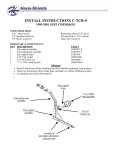
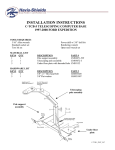
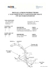
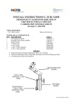
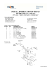
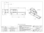
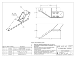
INSTALL INSTRUCTIONS C-TCB-26
2002-2008 FORD EXPLORER
TOOLS REQUIRED:
Torx Bit Set (T-55)
3/16” Allen wrench
3/8” Standard Socket Set
3/8” Metric Socket Set
3/8” Ratcheting Wrench
Powered drill
3/16” & 5/16” Drill bits
Open-end wrench set
HARDWARE:
QTY DESCRIPTION
1
Pole support assembly
1
Telescoping pole assembly
1
Side support brace
1
5/16” Nylock nut
2
5/16” Flat washer
1
5/16-18 x 1” Hex head bolt
2
¼” x ¾” Hex head lag bolt
PART #
CM93071-26W
CM93072-1
CM93135
GSM30017
GSM31006
GSM33012
GSM33060-1
Always!
Read all instructions before installing any Havis-Shields Equipment Corp products.
Check for obstructions (Wire, brake lines, fuel tank, etc.) before drilling any holes!
Use hardware provided with install kit
Telescoping
pole assembly
Side support
brace
Pole support
assembly
Location of factory
seat bolts
C-TCB-26_INST_9-07
SUB ASSEMBLY:
1. Confirm receipt of all hardware and components.
2. Remove front inner and outer passenger seat bolts on vehicle.
INSTALLATION:
1. MOUNT TELESCOPING COMPUTER BASE:
• Position pole support assembly on top of passenger seat base mount and align holes in
pole support assembly with holes in seat base.
• Loosely attached factory seat bolts that were removed during subassembly.
• Loosely mount side support brace to threaded rod located on pole support assembly
using a 5/16-18 Nylock nut
• Mount side support brace to vehicle using ¼” x ¾” Hex head lag bolts. A 3/16” pilot
hole is required.
Note: When mounting side support brace to floor of vehicle, be sure to check for obstructions prior to
drilling or lag bolting to floor.
•
•
Tighten down factory passenger seat bolts and 5/16-18-nylock nut holding side
support brace to pole support assembly.
Mount optional C-3090, computer-mounting platform, to telescoping pole assembly
using hardware and instructions provided with C-3090.
C-TCB-26_INST_9-07