1
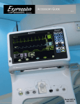
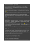
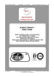
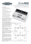
INVINCIBLE "RS" OWNERS
MANUAL
R6
1
Contents
Packing List
3
Installation & Assembly
3
Venting
5
Operation
9
ESP Control
12
Maintenance
13
Wiring Diagram
16
Feeder Parts
17
Trouble Shooting
18
Specifications
19
Warnings
20
Manufactured by
Harman Stove Company
352 Mountain House Road
Halifax Pa. 17032
(717) 362-9080
2
Packing List
Inside Stove:
Hardware Pack
(2) Electrical Terminals
(1) 10-32 x 1/2" Bolt
(1) 1/4 x 20 x 2 1/2" Bolt
(1) Wooden Handle
(1) Brass Knob
(1) Owners Manual
(1) Warranty Activation Coupon
(1) Room Sensing Probe
(1) Ash Pan
(2) Firebricks
(1) Scraper
(1) Flame Guide
(1) Cleaning Brush
Assembly and Installation
Hopper Knob
Final Assembly
Remove parts from ash pan.
Install Wooden Door Handle with
1/4 x 20 x 2 1/2 bolt.
Install Brass Hopper Knob with
10-32 x 1/2 bolt.
Install the two Firebricks on the
angle iron behind the burn pot as
shown in fig. 1.
Remove tape from Flame Guide
and make sure it is resting on the burn
pot as shown in fig. 1.
Put the ash pan back in the stove.
Firebricks
Flame Guide
Handle
Ash Pan
Fig. 1
3
Installing
Place the stove on a noncombustible floor protector and away from combustible walls at least as
far as shown in figure 2 and 3. Note that the clearances shown are minimum for safety but do not leave
much room for access when cleaning or servicing.
Please take this into account when placing the stove.
Place the Room Sensing Probe in the desired
location and run standard thermostat wire back to
the terminals on the back of the stove and connect
with the two terminals provided. Unlike a wall thermostat the RS probe can be placed anywhere and go
unnoticed. We recommend the room sensor be installed even if only cut short and connected to room
sensor remote ports.
Connect the power cord to a 120 volt receptacle.
Prior to installing flue pipe, connect draft and
meter to stove. (The draft meter must have a minimum range of 0-.5). Connect stove to 120V power
source. Set control board to test mode. Record draft
reading here _______ (should read at least .5").
After connecting the flue system, follow the
above procedure. However, prior to taking the draft
reading be sure all doors and windows to the home
are closed. Record the draft reading_______. If this
reading is more than .1" lower than the unconnected
reading check for possible restrictions or the need
for outside air (see page 5).
3"
Fig. 2
2"
1"
Mobile Home Installation
When installing the Invincible RS in a mobile
home it is required that the stove be bolted to the
floor. This is usually done inside the pedistal base
where the bolt will not be visible and requires drilling a hole where it is best suited.
6"
12"
6"
Fig. 3
4
Venting
A combustion blower is used to extract the combustion gases from the firebox. This causes a negative pressure in the firebox and a positive pressure in
the venting system as shown in fig. 4. The longer the
vent pipe and more elbows used in the system, the
greater the flow resistance. Because of these facts
we recommend using as few elbows as possible and
15 feet or less of vent pipe. If more than 15 feet of
pipe is needed, the diameter should be increased from
3" to 4" because a larger pipe causes less flow resistance. Be sure to use approved pellet vent pipe and
wall pass through fittings.
Vent Pipe
Pellet venting pipe ( also known as PL vent ) is
constructed of two layers with an air space between
them. This air space acts as an insulator and reduces
the outside surface temperature to allow a clearance
to combustibles of only 3 inches. The sections of pipe
lock together to form an air tight seal in most cases
however, in some cases a perfect seal is not achieved.
For this reason and the fact that the Invincible RS
operates with a positive vent pressure we specify that
the joints also be sealed with clear silicone.
+ = Positive static pressure
= Negative static pressure
Fig. 4
Outside Air
Outside air is optional except in mobile homes
and where building codes require. The benefit of
outside air is mainly noticed in small very tight houses.
To install outside air use 2" sch 40 plastic pipe
inserted through the back of the stove. The pipe
should be run outside and terminate 3 feet or more to
the side or below the vent pipe outlet. Never terminate the outside air above the vent pipe outlet. From
the stove and through the wall the PVC must be kept
3" from PL vent pipe.
HRV
When installing in a house with a Heat Reclaiming Ventilation System (HRV) be sure the system is
balanced and is not creating a negative pressure in
the house.
5
#1 Preferred method
This method provides excellent venting for normal operation and allows the stove to be installed
closest to the wall. Two inches from the wall is safe,
however, four inches allows better access to remove
the rear panel. The vertical portion of the vent should
be three to five feet high. This vertical section will
provide natural draft in the event of a power failure.
3 ft.
to combustibles
Fig. 5
#2 Preferred method
This method also provides excellent venting for
normal operation but requires the stove to be installed
farther from the wall. The vertical portion of the vent
should be three to five feet high and at least three
inches from a combustible wall. This vertical section
will provide natural draft in the event of a power failure.
CAUTION
3 ft.
KEEP COMBUSTIBLES (SUCH
AS GRASS, LEAVES, ETC.) AT
LEAST 3 FEET AWAY FROM THE
FLUE OUTLET ON THE
OUTSIDE OF THE BUILDING.
to combustibles
Fig. 6
6
#4 Installing into an existing
chimney ( US only )
This method provides excellent venting for normal operation. This method also provides natural
draft in the event of a power failure. If the chimney
condition is questionable you may want to install a
liner as in method #7.
Fig. 7
#5 Installing into an existing
fireplace chimney ( US only )
This method provides excellent venting for normal operation. This method also provides natural
draft in the event of a power failure.
The damper area must be sealed with a steel
plate or fiberglass. A cap should be installed on the
chimney to keep out rain. If the chimney condition is
questionable you may want to install a liner all the
way to the top as in method #6.
Fig. 8
7
#6 Installing into an existing
fireplace chimney ( US and
Canada )
This method provides excellent venting for normal operation. This method also provides natural
draft in the event of a power failure.
In Canada and some places in the US it is required that the vent pipe extend all the way to the
top of the chimney.
In this method a cap should also be installed on
the chimney to keep out rain. Be sure to use approved
pellet vent pipe fittings. Seal pipe joints with silicone
in addition to the sealing system used by the manufacturer. Pipe size should be increased to 4" using
this method.
Fig. 9
#7 Installing into an existing
chimney ( US and Canada )
This method provides excellent venting for normal operation. This method also provides natural
draft in the event of a power failure.
In Canada and some places in the US it is required that the vent pipe extend all the way to the
top of the chimney. The pipe or liner inside the chimney should be 4"diameter.
In this method a cap should also be installed on
the chimney to keep out rain. One disadvantage of
this method is that it is harder to clean the vent pipe,
therefore, there is a tendancy not to do it as often as
needed.
Fig. 10
8
DO NOT INSTALL A FLUE DAMPER IN THE
EXHAUST VENTING SYSTEM OF THIS
UNIT.
WARNING
DO NOT INSTALL IN SLEEPING ROOM
DO NOT CONNECT THIS UNIT TO A
CHIMNEY FLUE SERVING ANOTHER
APPLIANCE.
CAUTION
INSTALL VENT AT CLEARANCES
SPECIFIED BY THE MANUFACTURER
THE STRUCTURAL INTEGRITY OF THE
MOBILE HOME FLOOR, WALL, AND
CEILING/ROOF MUST BE MAINTAINED.
Mobile home installation should be done in
accordance with the Manufactured Home and
Safety Standard (HUD), CFR 3280, Part 24.
3'
WARNING
Keep combustible materials such as grass,
leaves, etc. at least 3 feet away from the
point directly under the vent termination.
9
Operation
Starting First Fire
Be sure the power cord is plugged into a 120 volt
receptacle. This can be verified by the red power
light on the control panel.
Fill the hopper with pellets, fig. 12.
Fill the burn pot with pellets to a level just short
of overflowing, fig. 8.
Fig. 8
Adjust feed rate. If this is your first fire or you
are trying different pellets, set the feed adjuster
to "3", fig. 9. This is a conservative number and
will probably need to be increased. After you
know a feed rate setting that works well, use
that setting. Remember, too high a feed rate will
waste fuel.
Fig. 9
Fig. 10
1"
Turn Mode selector to "OFF" and then to
"Stove Temp". This will turn the combustion
blower to high. When starting a fire always turn
the mode selector to "OFF" before selecting the
desired mode. This resets the control for startup.
Turn Temp Dial to 7. This will allow the stove to
burn at maximum for feed rate adjusting purposes.
Apply starting gel to pellets in burn pot and light
the gel. Close the door after lighting. At this
point the distribution and combustion lights will
be on and the feed motor light will be off. As the
temperature of the fire increases, the feed motor
light will come on and pellets will feed into the
burn pot. As the stove temperature increases the
distribution blower speed will increase.
After 30 to 45 minutes it may be necessary to
readjust the feed rate. The feed rate should be
adjusted so there is about one inch of ash in
front of the fire, fig. 10A. This is a maximum
burn position and usually does not achieve this
position under normal burn rates.
Fig. 10A
10
Scrape floor of burn pot with scraper to
remove any carbon build-up before
starting a new fire.
Starting a fire after proper
Feed Rate is known.
Clean burn pot with scraper (supplied).
Fill the hopper with pellets.
Fill the burn pot with pellets to a level just short
of overflowing.
Fig. 11
When filling hopper be sure to
remove any pellets from ledge
and around hinges before
closing lid.
Adjust feed rate to proper setting.
After you know what feed rate works well, then
use that setting. (For example a setting of "5"
produces 1" or more of ash on the burn pot with
the brand of pellets you are using.) Remember,
too high a feed rate will waste fuel.
Turn Mode selector to "OFF" and then to the
desired mode.
Turn Temp Dial to the desired temperature. In
Room Temp Mode this would be the outer scale
marked in degrees. In Stove Temp Mode this
would be the inner scale marked from 1 to 7.
Apply starting gel to pellets in burn pot as shown
in fig. 10 and light the gel. Close the door after
lighting.
At this point the distribution and combustion lights
will be on and the feed motor light will be off.
As the temperature of the fire increases, the feed
motor light will come on and pellets will feed
into the burn pot. As the stove temperature
increases the distribution blower speed will
increase.
11
Fig. 12
Fig. 13
When to use "Stove Temp
Mode"
In "Stove Temp Mode" the Stove Temp Dial
determines the temperature of the stove. Heat
output and fuel consumption will remain constant. This makes it possible to tell how long a
hopper full of pellets will last. The distribution
blower speed will vary according to the position
of the mode selector, fig. 13.
When to use "Room Temp
Mode"
This setting will produce medium heat with the
distribution blower on "low".
This setting will produce a room temperature of 70
degrees with the distribution blower at medium speed.
In "Room Temp Mode" heat output is controlled
automatically by the Room Sensing Probe. When the
Room Sensing Probe calls for heat, the stove will
increase output. When the Room Sensing Probe is
getting close to the set temperature, the stove will
begin to level off output and keep the fire burning at
just the right temperature to maintain that setting.
High output is determined by the feed rate. The
maximum feed rate should be set for 1" of ash in
front of fire.
In "Room Temp Mode" fuel consumption is sacrificed for exact room temperature. Therefore, as it
gets colder more pellets will be burned automatically.
The distribution blower speed will vary according to the position of the mode selector, fig. 13.
Shut-Down Procedure
To kill the fire or stop burning the stove, turn
the Mode Selector to "OFF". This will cause the fire
to diminish and burn out. When the fire burns out
and the stove cools down everything will stop.
If you pull the plug to shut down the stove, all
motors will stop. This may cause incomplete combustion and smoke in the firebox. If the load door is
opened the smoke may escape.
The best way to shut down the stove is simply
let it run out of pellets, then the stove will shut down
automatically.
This setting will produce continuous maximum heat output
with the distribution blower at full speed.
12
ESP CONTROL
Power Light
Indicates power to the
control.
Secondary function:
Blinks every 15 seconds
when the feed adjuster is
in "Test Mode". This
verifies feeder switch
operation. Should be lit
anytime the unit is pluged
in.
Feed adjuster
Sets the maximum feed
rate
Test
Runs all motors at
full speed for two
minutes to check
operation. After two
minutes the stove
will go to minimum
burn and the blowers
will alternate from
high to low every two
minutes to remind
you that you are still
in "Test Mode".
Status Light
Will be lit in either stove
or room temp mode when
pointer is not within off
position band except after
normal shut down. Blinks
to indicate errors listed
listed below.
Indicates power to
distribution blower.
Distribution Blower
speed adjustment range.
Indicates Power to
combustion blower
Indicates Power to the
feed motor.
Temp dial
Allows you to adjust the Room temperature
in Room Temp Mode using the outer scale
marked in degrees Fahrenheit. It also
allows you to adjust the stove temperature
while in Stove Temp Mode using the inner
scale marked from 1 to 7.
Status light error messages:
1 Blink: Indicates control board self diagnostic failure. This requires a manual reset*.
2 Blinks: Indicates that the feeder position switch
has not sensed the slide plate in the home position
for 30 minutes. This means that the slide plate may
be stuck due to a foreign object in the fuel or the
switch has failed. If the switch has failed the stove
will operate normally, however if turned to the "OFF
" position the stove will go to minimum burn and will
only shut down when it runs out of fuel. If the slide
plate frees itself the status light will automatically
Mode Selector
Allows you to choose between Room
Temp Mode, Stove Temp Mode, or OFF.
Also allows you to vary the distribution
blower speed by turning the knob to the
high or low side of each mode.
reset. If the error continues call your Harman Dealer.
3 Blinks: Indicates ESP (Exhaust Sensing Probe)
failure. This requires a manual reset*.
4 Blinks: Can occur only in Room Temp Mode and
indicates Room Sensing Probe failed or not installed.
If a Room Sensing Probe is then installed the status
light will automatically reset.
(Note) only after unit has warmed up.
* Manual reset, disconnect power cord for a few
seconds and reconnect. If error still occurs call your
Dealer.
13