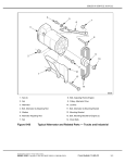
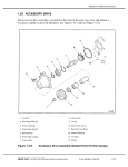
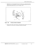
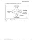
1
SERIES 60 SERVICE MANUAL
4. The procedure for measuring the lash between the bull gear and the fuel pump drive gear
(if applicable) and the air compressor and power steering pump drive gear is similar to
the steps just mentioned. Refer to step 3 and perform step 3[a], as the first step and
refer to step 3[g], as the final step. Gear case cover must be installed to continue on
checking the engine timing. Refer to section 1.10.3 and perform all of the steps under gear
case cover installation.
NOTE:
Due to the possibility of damaging the crankshaft front oil seal, whenever the gear case
cover is removed, the front crankshaft oil seal must be replaced. Replace the crankshaft
front oil seal after the gear case cover is installed. Refer to section 1.8.1.
5. The procedure for measuring the lash between the accessory drive gear and air compressor
pump drive gear (on vehicle without power steering) is similar to the steps just mentioned.
Refer to step 3and perform step 3[a], as the first step and refer to step 3[g], as the final step.
NOTE:
Lash can be measured with the gear case cover installed. Access covers are provided
for checking the lash between these gears and the bull gear. For engines with no access
cover for accessory drive, gear lash is to be measured off the accessory drive pulley.
6. The procedure for measuring the lash between the adjustable idler gear and camshaft drive
gear is similar to the steps just mentioned. Refer to step 3 and perform step 3[a], as the
first step and refer to step 3[g], as the final step.
NOTE:
These gears are measured and adjusted with the gear case cover installed.
7. The procedure for measuring the lash between the bull gear and the water pump drive gear
is similar to the steps just mentioned. Refer to step 3 and perform step 3[a], as the first
step and refer to step 3[g], as the final step.
NOTE:
These gears can be measured with the pump installed.
All information subject to change without notice.
(Rev. 11\03)
6SE483 0303 Copyright © 2003 DETROIT DIESEL CORPORATION
From Bulletin 14-60-03
1-405
1.21
GEAR TRAIN AND ENGINE TIMING
NOTICE
For engines equipped with the compact gear train assembly go
to step 9 for measuring and adjusting gear lash procedures.
8. When measuring or adjusting the gear lash between the adjustable idler gear and the
camshaft drive gear, the valve and injector spring pressures must be removed from the
camshaft lobes. Use the following procedure for this adjustment:
NOTE:
The front and rear rocker shafts look identical, but must not be interchanged due to
different oil passage patterns. The outboard ends of the rocker arm shafts are marked for
identification with the DDC logo. See Figure 1-330. Use care to ensure that the rocker
arm shaft assemblies are replaced exactly as removed.
Figure 1-330
Rocker Arm Shaft Identification Mark
(Rev. 11\03)
1-406
From Bulletin 14-60-03
All information subject to change without notice.
6SE483 0303 Copyright © 2003 DETROIT DIESEL CORPORATION
SERIES 60 SERVICE MANUAL
[a]
Install the gear lash pedestal, J 35596-15, into the threaded hole of the camshaft
drive gear. See Figure 1-331. Bar the engine over until the tool is at the three
o’clock position.
1. Gear Lash Adjustment Tool
4. Dial Indicator
2. Adjustable Idler Gear Retaining Nut
5. Pedistal Idler Gear Hole
3. Magnetic Base
6. Adjustable Idler Gear Retaining Nut
Figure 1-331
Camshaft Drive Gear-to-Adjustable Idler Gear Lash Measurement
NOTE:
Since the teeth of the camshaft drive gear are not accessible with the gear case cover
installed, the lash is measured on the pedestal installed in the threaded hole, which is
located exactly half-way between the center and edge of the camshaft drive gear. For
this reason, the reading obtained will be exactly 1/2 of the actual gear lash.
[b]
Mount a dial indicator adaptor and dial indicator. See Figure 1-331.
[c]
Adjust the stem of the dial indicator to rest on the flat of the pedestal.
[d]
If the adjustable idler gear has been removed, torque the three flanged nuts that retain
the adjustable idler gear hub to the gear case to 57-67 N·m (42-49 lb·ft) to seat the
assembly before proceeding.
[e]
Loosen the three locknuts that retain the adjustable idler gear hub to the gear case
until they are hand tight.
[f]
Insert the dowel portion of the gear lash adjusting tool, J 35596, through the hole in
the adjustable idler gear retaining plate and into the adjustable idler gear hub, using
the bottom two adjustable idler gear cover bolt holes. See Figure 1-331.
All information subject to change without notice.
(Rev. 11\03)
6SE483 0303 Copyright © 2003 DETROIT DIESEL CORPORATION
From Bulletin 14-60-03
1-407
1.21
GEAR TRAIN AND ENGINE TIMING
[g]
Turn the adjusting screw of the tool in a clockwise direction to force the adjustable
idler gear against the camshaft drive gear, until there is zero lash between the two
gears. See Figure 1-332.
Figure 1-332
Adjustable Idler Gear-to-Camshaft Drive Gear Lash Adjustment
[h]
Zero the dial indicator.
[i]
Hold the adjustable idler gear by inserting a screwdriver through the hole provided
in the gear case. Engage one of the adjustable idler gear teeth and apply pressure
on the screwdriver to move the gear in a counterclockwise direction. This will
prevent the gear from moving.
[j]
Attempt to turn the camshaft drive gear, and watch the dial indicator pointer.
NOTE:
If there is zero lash between the two gears, the dial indicator pointer will not move from
zero.
[k]
Turn the adjusting screw of the gear lash adjusting tool, J 35596, approximately 1-1/2
turns or until the proper gear lash is obtained.
(Rev. 11\03)
1-408
From Bulletin 14-60-03
All information subject to change without notice.
6SE483 0303 Copyright © 2003 DETROIT DIESEL CORPORATION
SERIES 60 SERVICE MANUAL
[l]
When checking gear lash, hold the adjustable idler gear stationary . Refer to step 8[i]
as the first step and refer to step 8[j]as the final step, and rotate the camshaft drive
gear with your right hand. See Figure 1-333.
Figure 1-333
Checking Adjustable Idler Gear-to-Camshaft Drive Gear Lash
NOTE:
Remember to multiply the reading obtained by two to get the actual lash measurement.
The specification of gear lash is 0.051-0.229 mm (0.002 -0.009 in.) with a maximum
of 0.305 mm (0.012 in.) for used parts.
[m]
Check the gear lash with the pedestal at the 3, 6, 9 and 12 o’clock positions, exactly
as previously performed.
[n]
When the proper readings of 0.025-0.114 mm (0.001-0.0045 in.) are obtained at
all four (4) positions, hold the idler gear. Refer to step 8[i]as the first step and
refer to step 8[j] as the final step, and torque the top two adjustable idler gear flanged
nuts to 57-67 N·m (42·49 lb·ft).
[o]
Check the gear lash again as outlined above, with the flanged nuts torqued, to ensure
that gear lash is still within limits. If not correct repeat the procedure.
[p]
If proper lash measurement cannot be obtained, replace gear(s) with new part(s).
Refer to section 1.24.2, refer to section 1.25.2, refer to section 1.27.2and
refer to section 1.26.2.
[q]
Remove the gear lash adjusting tool from the gear case.
[r]
Torque the bottom adjustable idler gear flanged nut to 57-67 N·m (42-49 lb·ft) torque.
[s]
Remove the dial indicator and pedestal from the gear case.
All information subject to change without notice.
(Rev. 11\03)
6SE483 0303 Copyright © 2003 DETROIT DIESEL CORPORATION
From Bulletin 14-60-03
1-409
1.21
GEAR TRAIN AND ENGINE TIMING
[t]
Before installing the rocker arm shaft assemblies, check the torque on the end studs
to ensure they were not loosened at time of removal. The torque specification
is 101-116 N·m (75-86 lb·ft).
[u]
Install the rocker arm shaft assemblies to the cylinder head. Refer to section 1.3.3.
[v]
Adjust the intake and exhaust valve clearances, and fuel injector heights.
Refer to section 12.2.
[w]
Install the valve rocker cover. Refer to section 1.6.8 for a one-piece valve rocker
cover and refer to section 1.6.9for two-piece and three-piece rocker covers.
[x]
Install the camshaft drive gear access cover and the gear case cover.
Refer to section 1.10.3.
(Rev. 11\03)
1-410
From Bulletin 14-60-03
All information subject to change without notice.
6SE483 0303 Copyright © 2003 DETROIT DIESEL CORPORATION
SERIES 60 SERVICE MANUAL
9. The procedures for measuring and adjusting the gear lash for the compact gear train
are as follows:
[a]
Install the gear lash pedestal tool, J 46303 onto the center of the camshaft drive
gear. See Figure 1-333a. Bar the engine over until the tool is at the three o’clock
position.
[b]
Attach the magnetic base on dial indicator to the gear case cover. Adjust it so the dial
indicator is positioned at a 90 angle to the measuring bar and is at the scribe line
on the bar. See Figure 1-333a.
1. Adjustable Idler Gear Retaining Nut
3. Dial Indicator
2. Magnetic Base
Figure 1-333a
Compact Gear Train Gear Lash Measurement
NOTE:
Since the teeth of the camshaft drive gear are not accessable, the gear lash measuring
adaptor has a predetermined spot where the lash measurement must be taken. The
measurement bar must be installed into the magnetic base correctly and the dial
indicator positioned between the marks at the end of the bar.
[c]
Adjust the stem of the dial indicator to rest on the flat of the pedestal between the
scribed marks on the end bar at a 90 angle.
[d]
If the adjustable idler gear has been removed, torque the three flanged nuts that retain
the adjustable idler gear hub to the gear case to 57-67 N·m (42-49 lb·ft) to seat the
assembly before proceeding.
All information subject to change without notice.
(Rev. 11\03)
6SE483 0303 Copyright © 2003 DETROIT DIESEL CORPORATION
From Bulletin 14-60-03
1-411
1.21
GEAR TRAIN AND ENGINE TIMING
[e]
Loosen the three locknuts that retain the adjustable idler gear hub to the gear case
until they are hand tight.
[f]
Insert the dowel portion of the gear lash adjusting tool J 35596 , through the hole in
the adjustable idler gear retaining plate and into the adjustable idler gear hub, using
the bottom two adjustable idler gear cover bolt holes. See Figure 1-333a.
Figure 1-333b
Compact Gear Train Lash Adjustment
NOTE:
For Series 60 engines equipped with the compact gear train, tool J 35596 needs to be
modified to fit the four bolt pattern of the idler gear cover. A simple modification to the
mounting plate will allow it to be securely bolted to the cover.
[g]
Hold the adjustable idler gear by inserting a screwdriver through the access hole
provided in the gear case cover. Engage between two of the idler gear teeth and apply
upward pressure on the screwdriver to move the gear in a counterclockwise direction.
This will prevent the gear from moving. See Figure 1-333b
[h]
Rotate the camshaft by hand and watch the dial indicator pointer.
[i]
Turn the adjusting screw of the gear lash adjusting tool J 35596 , approximately 1-1/2
turns. Gear lash should be 0.051-0.229 mm (0.002-0.009 in.). Hold the adjustable
idler gear with screwdriver refer to step [g]. Repeat steps [h] and [i] until proper
lash is obtained.
NOTE:
If there is zero lash between the two gears, the dial indicator pointer will not move from
zero.
(Rev. 11\03)
1-412
From Bulletin 14-60-03
All information subject to change without notice.
6SE483 0303 Copyright © 2003 DETROIT DIESEL CORPORATION
SERIES 60 SERVICE MANUAL
[j]
Check the gear lash with the pedestal at 3, 6, 9, and 12 o’clock positions, exactly as
previously performed.
[k]
When the proper readings of 0.051-0.229 mm (0.002-0.009 in.) are obtained at all
four positions, hold the idler gear and torque the three adjustable idler gear flanged
nuts to 103-113 N·m (76-83 lb·ft.).
[l]
Remove the gear lash adjusting tool and check the gear lash again. Refer to step 9 [j].
If gear lash is not correct repeat steps 9 [e] through steps 9 [j].
[m]
If proper lash measurement cannot be obtained , replace gear(s) with new part(s).
[n]
Remove the dial indicator and pedestal from the gear case.
[o]
Before installing the rocker arm shaft assemblies, check the torque on the end studs
to ensure they were not loosened at the time of removal. The torque specification
is 101-116 N·m (75 -86 lb·ft).
[p]
Install the rocker arm shaft assemblies to the cylinder head. Refer to section 1.3.3.
[q]
Adjust the intake and exhaust valve clearances, and fuel injector
heights. Refer to section 12.2.
[r]
Install the valve rocker cover. Refer to section 1.6.8 for a one-piece valve rocker
cover and refer to section 1.6.9 for two piece and three piece rocker covers.
[s]
Install the camshaft drive gear access cover and the gear case cover.
Refer to section 1.10.3.
All information subject to change without notice.
(Rev. 11\03)
6SE483 0303 Copyright © 2003 DETROIT DIESEL CORPORATION
From Bulletin 14-60-03
1-413
1.21
GEAR TRAIN AND ENGINE TIMING
10. Install the fan support bracket "if required" as follows:
[a]
Clean the mating surfaces of the fan support bracket and gear case of all old gasket
eliminator. Refer to the section on "Gasket Eliminator" in the "General Information"
section at the beginning of this manual.
[b]
Apply a 1/16 in. bead of Gasket Eliminator PT-7276 (Loctite® 518), or equivalent,
to the machined surface of the gear case cover surrounding the adjustable idler
gear access.
[c]
Install the fan support bracket to the gear case cover using the torque values and
tightening sequence. See Figure 1-334.
Bolt
Torque
1-3-5
58-73 N·m (43-54 lb·ft)
2-4
160-200 N·m (118-148 lb·ft)
6 to 10
30-38 N·m (22-28 lb·ft)
Figure 1-334
Fan Support Bracket Bolt Torque Sequence
(Rev. 11\03)
1-414
From Bulletin 14-60-03
All information subject to change without notice.
6SE483 0303 Copyright © 2003 DETROIT DIESEL CORPORATION
SERIES 60 SERVICE MANUAL
11. Check the bull gear-to-accessory drive gear lash measurement as follows:
[a]
Install the gear lash tool, J 38662 and mount a magnetic dial indicator base and dial
indicator to the gear case cover. See Figure 1-335.
Figure 1-335
Accessory Drive Gear-to-Bull Gear Lash Measurement
[b]
Position the dial indicator to read between the scribed lines on the tool.
See Figure 1-335.
[c]
Rotate the accessory drive pulley, read and record the total gear lash.
[d]
Gear lash measurements are 0.051-0.229 mm (0.002 -0.009 in.) for new parts, and
0.305 mm (0.012 in.) for used parts.
[e]
If proper lash measurement cannot be obtained, replace gear with a new part.
Refer to section 1.26.2.
[f]
Remove the dial indicator and gear lash tool.
All information subject to change without notice.
(Rev. 11\03)
6SE483 0303 Copyright © 2003 DETROIT DIESEL CORPORATION
From Bulletin 14-60-03
1-415
1.21
GEAR TRAIN AND ENGINE TIMING
12. Check the bull gear-to-water pump drive gear lash measurement for 1991 and later engines
(with water pump impeller slip tester, J 35687-1) as follows:
NOTE:
The bull gear-to-water pump drive gear lash can be measured using the water pump
impeller slip tester, J 35687-1, refer to step 12[a] through step 12[g]. Or by using the
water pump gear lash tool, J 38977, refer to step 13. Engines built early in 1991 will
need the water pump gear lash checked with the slip tester. These engines do not have
a threaded hole in the water pump drive gear retaining bolt to accept the gear lash tool.
To avoid injury from flying parts when working with
components under spring tension, wear adequate eye
protection (face shield or safety goggles).
[a]
Remove the water pump cover snap ring with snap ring pliers. Remove water pump
cover and seal ring.
[b]
Install the water pump impeller slip tester, J 35687-1, to the water pump impeller with
two 5/16-18 bolts, using the instructions supplied with the tool. See Figure 1-336.
Figure 1-336
Water Pump Impeller Slip Tester Method
(Rev. 11\03)
1-416
From Bulletin 14-60-03
All information subject to change without notice.
6SE483 0303 Copyright © 2003 DETROIT DIESEL CORPORATION
SERIES 60 SERVICE MANUAL
[c]
One leg (the long one) of the tool has an inscribed line. Measuring with a dial
indicator at this line of the tool, the gear lash measurement will be an exact 1:1
reading. Gear lash specifications are 0.051-0.229 mm (0.002 -0.009 in.).
[d]
If proper lash cannot be obtained, replace gear with a new part. Refer to section 1.26.2.
[e]
Remove the dial indicator.
[f]
Remove the tool from the water pump.
[g]
Inspect the water pump cover seal for cracks or splitting. Refer to section 4.2.3.1
gear mounted or refer to section 4.3.3 for front mounted water pump. Replace seal if
damage is found.
All information subject to change without notice.
(Rev. 11\03)
6SE483 0303 Copyright © 2003 DETROIT DIESEL CORPORATION
From Bulletin 14-60-03
1-417
1.21
GEAR TRAIN AND ENGINE TIMING
13. Check the bull gear-to-water pump drive gear lash measurement for 1991 and later engines
(with water pump gear lash tool, J 38977) as follows:
[a]
Remove the pipe plug in the gear case cover.
[b]
Install the water pump gear lash tool, J 38977-A, through the hole in the gear case
and thread it into the special water pump drive gear retaining bolt. See Figure 1-337.
Figure 1-337
Water Pump Gear Lash Tool Method
[c]
The arm of this tool has an inscribed line. Measuring with a dial indicator at this
line of the tool, the gear lash measurement will be an exact 1:1 reading. Gear lash
specifications are 0.051-0.229 mm (0.002 -0.009 in.).
[d]
If proper lash cannot be obtained, replace the gear with a new part. Refer to section
1.26.2.
[e]
Remove the dial indicator and the gear lash tool.
[f]
Install the pipe plug in the gear case cover. Torque to 24-31 N·m (18-23 lb·ft).
(Rev. 11\03)
1-418
From Bulletin 14-60-03
All information subject to change without notice.
6SE483 0303 Copyright © 2003 DETROIT DIESEL CORPORATION
SERIES 60 SERVICE MANUAL
14. Check the bull gear-to-water pump drive gear lash measurement of pre-1991 engines (with
the water pump impeller slip tester method) as follows.
NOTE:
Skip step 14 and the following step 15, if the engine was built after 1990.
NOTE:
The bull gear-to-water pump drive gear lash can be measured using the water pump
impeller slip tester, J 35687-1, or by inserting a bolt into one of the tapped holes in the
water pump impeller. The lash can then be measured using a dial indicator.
[a]
Install the water pump impeller slip tester, J 35687-1, to the water pump impeller with
two 5/16-18 bolts, using the instructions supplied with the tool. See Figure 1-338.
Figure 1-338
Water Pump Drive Gear Lash Measurement
[b]
One leg (the long one) of the tool has an inscribed line. Measuring with a dial
indicator at this line of the tool, the gear lash measurement will be an exact 1:1
reading. Gear lash specifications are 0.051-0.229 mm (0.002 -0.009 in.).
[c]
If proper lash measurement cannot be obtained, replace the gear with a new part.
Refer to section 1.26.2 .
All information subject to change without notice.
(Rev. 11\03)
6SE483 0303 Copyright © 2003 DETROIT DIESEL CORPORATION
From Bulletin 14-60-03
1-418a
1.21
GEAR TRAIN AND ENGINE TIMING
15. Check the bull gear-to-water pump drive gear lash measurement for pre-1991 engines
(with the bolt method) as follows:
[a]
Install a 5/16-18 bolt and nut into one of the tapped holes in the water pump impeller.
See Figure 1-339.
Figure 1-339
Water Pump Drive Gear-to-Bull Gear Lash Measurement
[b]
Install a magnetic dial indicator base and dial indicator. See Figure 1-339.
[c]
Position the stem of the dial indicator on a flat of the bolt.
[d]
Preload the water pump impeller.
[e]
Zero the dial indicator.
[f]
Rotate the water pump impeller, read and record the total gear lash. Multiply this
reading by 2.45 to obtain actual lash. Gear lash measurements are 0.051 to 0.229
mm (0.002 -0.009 in.).
[g]
If proper lash cannot be obtained, replace the gear with a new part.
Refer to section 1.26.2.
[h]
Remove the dial indicator base and dial indicator.
[i]
Remove the bolt and nut from the water pump impeller (if used).
[j]
Inspect the rubber seal ring on the water pump cover for splitting or cracks. Install a
new seal, if necessary, between the water pump cover and the water pump housing.
Refer to step 12, and perform step 12[g].
[k]
Install the two bolts that secure the water pump cover to the water pump housing.
Torque the bolts to 30-38 N·m (22-28 lb·ft).
(Rev. 11\03)
1-418b
From Bulletin 14-60-03
All information subject to change without notice.
6SE483 0303 Copyright © 2003 DETROIT DIESEL CORPORATION
SERIES 60 SERVICE MANUAL
16. Check the bull gear-to-air compressor drive gear lash measurement as follows:
[a]
Mount a magnetic dial indicator base and dial indicator to the gear case cover so that
the stem of the dial indicator may be positioned on a tooth of the air compressor
drive gear.
[b]
Preload the drive gear in one direction.
[c]
Zero the dial indicator.
[d]
Rotate the air compressor drive gear, read and record the total gear lash. Gear lash
measurements are 0.051-0.229 mm (0.002 -0.009 in.) for new parts, with a maximum
of 0.305 mm (0.012 in.) for used gears.
[e]
If proper lash cannot be obtained, replace the gear with a new part.
Refer to section 1.26.2.
[f]
Remove the dial indicator and magnetic base.
[g]
Install the power steering drive coupling to the air compressor drive gear (if equipped
with power steering) and insert a new O-ring on the power steering pump (if so
equipped).
[h]
Install the power steering pump to the gear case cover, meshing the drive coupling
properly.
[i]
Install and torque the power steering pump mounting bolts to 30-38 N·m (22-28 lb·ft).
Tighten the five bolts alternately and evenly, in a star-shaped pattern, to progressively
draw the power steering pump into the gear case cover.
NOTE:
Do not force the bolts. If resistance is encountered, remove the power steering pump
and re-engage the drive hub with the coupling.
[j]
If the engine is not equipped with power steering, install the air compressor drive
gear access cover using a new gasket.
[k]
Install and torque the retaining bolts to 30-38 N·m (22-28 lb·ft), using a star-shaped
pattern.
All information subject to change without notice.
(Rev. 11\03)
6SE483 0303 Copyright © 2003 DETROIT DIESEL CORPORATION
From Bulletin 14-60-03
1-418c
1.21
GEAR TRAIN AND ENGINE TIMING
1.21.3
Installation of Gear Train and Engine Timing
After all of the gear lash measurements have been taken, assemble the engine components
as follows:
1. Install the air conditioner compressor and brackets (if so equipped). Install the air
conditioner drive belt.
2. Install the alternator and brackets. Refer to section 8.2.3.
3. Install the alternator drive belts. Refer to section 13.13.10.
4. Install the fan and fan hub assembly. Refer to section 4.7.6.
5. Adjust the alternator, fan and air conditioner compressor drive belts to the specifications.
Refer to section 13.13.10. Torque the accessory mounting bolts to specifications.
6. Install any other equipment such as hoses, brackets, lines or electrical looms that were
removed to gain access to the engine gear case cover.
7. Install the engine oil pan. Refer to section 3.11.4.
8. Fill the engine crankcase. Refer to section 13.13.1.
9. Refer to section 11.8for verification of proper gear train and engine timing.
(Rev. 11\03)
1-418d
From Bulletin 14-60-03
All information subject to change without notice.
6SE483 0303 Copyright © 2003 DETROIT DIESEL CORPORATION