1
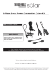
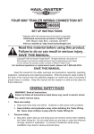
LED MOTION
99938 DETECTOR
LIGHT
Instructions and precautions
Distributed exclusively by Harbor Freight Tools®.
3491 Mission Oaks Blvd., Camarillo, CA 93011
Visit our website at: http://www.harborfreight.com
Save these instructions. Read all
precautions and instructions.
Copyright© 2008 by Harbor Freight Tools®. All rights reserved. No portion of this document or any artwork contained
herein may be reproduced in any shape or form without the express written consent of Harbor Freight Tools.
Diagrams within this document may not be drawn proportionally. Due to continuing improvements, actual product
may differ slightly from the product described herein. Tools required for assembly and service may not be included.
For technical questions or replacement parts, please call 1-800-444-3353.
Specifications
Light Dome
6 LED, Bright White
Sensor Detector Range/Angle
16 ft. / 100 Deg.
2.
Wear ANSI-approved safety goggles.
3.
Keep assembly area clean and well lit.
4.
Keep bystanders out of the area during
mounting.
5.
Do not mount when tired or when under the
influence of drugs or medication.
Unpacking
When unpacking, make sure that the item
is intact and undamaged. If any parts are missing
or broken, please call Harbor Freight Tools at the
number shown on the cover of this document as
soon as possible.
Important SAFETY
Information
Assembly Precautions
1.
Mount only according to these instructions.
Improper mounting can create hazards.
Use Precautions
1.
This product is not a toy. Do not allow children to play with this item.
2.
Use for intended purpose(s) only.
3.
Inspect before use; do not use if parts are
loose or damaged.
4.
Maintain product labels and nameplates.
These carry important safety information.
If unreadable or missing, contact Harbor
Freight Tools for a replacement. Assembly
Instructions
Read the entire Important
Safety Information section at the
beginning of this document including
all text under subheadings therein
before set up or use of this product.
1.
2.
3.
4.
Operation
1.
2.
Mounting
This Motion Detector can be mounted on a
drywall or solid surface.
The weight of the batteries may not permit
mounting at an angle.
The Motion Detector is designed to operate
when placed in a dark area or room.
Inspect the area where the Motion Detector
is to be mounted for hidden wiring or piping.
3.
4.
5.
Mounting
Bracket
Clips
6.
5.
6.
7.
8.
Fig. 1
Using the Mounting Bracket (2) (see Fig. 1)
as a template, drill two 1/8" mounting holes.
a. Insert the two supplied plastic Wall Anchors
(5) into the holes if mounting onto drywall.
Place the mounting bracket against the
mounting surface aligning the holes.
Insert each screw through the holes in the
mounting bracket, and screw all the way into
the Wall Anchors (5) or solid stud surface.
The Mounting Bracket should now be securely mounted on the surface. Pull firmly to
be sure bracket is secure.
Back of Detector
Turn Motion Detector over and slide the battery
compartment cover downward (see Fig. 2.)
Install the four 1.5V AA batteries. (Supplied.)
a.The proper polarity is shown in the battery
compartment.
Replace the battery compartment cover.
The Motion Detector mounting clips can now
slide into the Mounting Bracket (2) clips.
The top of the Motion Detector has a three
position switch:
a. The left position turns the six LEDs manually on, and stays on.
b. The center position turns the LEDs off, and
stays off.
c. The right position enables the “Auto” feature.
d. Any movement within the specified area
turns the six LED lights on for one minute.
To replace batteries or change switch position, slide Detector upward and out from the
mounting bracket.
Parts List
Part
1
2
3
4
5
Description
Motion Detector
Mounting Bracket
AA Alkaline Batteries, 1.5V (Supplied)
Screws: 1-3/4"L x 1/8" Dia. (Not Shown)
Wall Anchors: 1-3/16"L x 3/16" ID (Not Shown)
Qty.
1
1
4
2
2
Record Serial Number Here:
Note:If product has no serial number, record
month and year of purchase instead.
Note:Some parts are listed and shown for illustration purposes only, and are not available
individually as replacement parts.
PLEASE READ THE FOLLOWING
CAREFULLY
The manufacturer and/or distributor has
provided the parts list and assembly diagram
in this document as a reference tool only.
Neither the manufacturer or distributor
makes any representation or warranty of any
kind to the buyer that he or she is qualified
to make any repairs to the product, or that
he or she is qualified to replace any parts of
the product. In fact, the manufacturer and/or
distributor expressly states that all repairs
and parts replacements should be undertaken
by certified and licensed technicians, and not
by the buyer. The buyer assumes all risk and
liability arising out of his or her repairs to the
original product or replacement parts thereto,
or arising out of his or her installation of
replacement parts thereto.
Fig. 2
SKU 99938
For technical questions, please call 1-800-444-3353.
Page 2