1
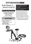
Specifications
Tire
Capacity
All tires from 8 IN. to Light
Truck Tires
(7-1/2 IN. x 16 IN.)
Flotation Tires: Up to 12.5L16
Includes
1 Bead Breaker Handle
37 IN. Long Mount/
Demount Tool
Important Safety Information
1.
Do not exceed max. tire
capacities. Do not use on standard
tires exceeding 16" or on flotation
tire exceeding size 12.5L16.
2.
CAUTION! Do not use on tires with
high-end rims. Tire removal and
installation can result in scratches
and slight marring on rims.
3.
Wear ANSI-approved safety goggles
and heavy-duty work gloves during
assembly, mounting and use.
4.
Do not modify Tire Changer to perform
tasks for which it was not designed.
5.
Use only with accessories
included with the Tire Changer.
6.
Do not use without mounting to floor.
Mount only to a secure, level surface
able to support weight of Manual
Tire Changer and tire assembly.
7.
Verify that mounting surface has
no hidden utility lines before
drilling or driving screws.
8.
9.
Lubricate Breaker Handle (7) when
removing tire from rim; failure do
so can lead to tire damage.
10. Keep work area clean and well lit.
11. Keep bystanders out of
the area during use.
12. Do not use when tired or when
under the influence of drugs,
medication or alcohol.
13. This product is not a toy. Do not allow
children to play with or near this item.
14. Inspect before every use; do not use
if parts are loose or damaged.
15. Maintain product labels and
nameplates. These carry
important safety information.
If unreadable or missing, contact
Harbor Freight Tools for a replacement.
16. WARNING: The brass components of
this product contain lead, a chemical
known to the State of California
to cause birth defects (or other
Deflate tire before use. Keep tire’s valve
reproductive harm). (California Health
stem uncovered during use to allow
& Safety code § 25249.5, et seq.)
any remaining air to flow out of tire.
Page 2
For technical questions, please call 1-888-866-5797.
Item 62317
Assembly/Mounting Instructions
Read the ENTIRE IMPORTANT SAFETY INFORMATION section
at the beginning of this document including all text under
subheadings therein before set up or use of this product.
1.
The Tire Changer will require
some assembly after unpacking.
See the assembly components
in Figure A, below.
3.
Fasten Center Post and Post Base
together using the Hex Bolts (6),
Washers (11), and Nuts (12).
See Figure B, below.
Mount/
Demount
Bar (14)
Center
Post (1)
Hex Bolts (6),
Washers (11)
and Nuts (12)
Post
Base (13)
Side
Bases (9)
Post
Base (13)
Hex
Bolts (6),
Washers
(11) and
Nuts (12)
Bead
Breaker
Handle
(7)
Bead Breaker
Shoe (10)
R-Clips (8)
Clevis
Pins (5)
Center
Post (1)
Figure B
4.
Set each of the Side Bases (9) along
either side of the Post Base until the
holes align. Fasten together using
the Hex Bolts (6), Washers (11), and
Nuts (12). See Figure C, below.
Center
Post (1)
Figure A
NOTE: Assembly of the Base
units (9, 13) to the Center Post (1) will
be easier if done on a worktable.
2.
Side
Base (9)
Set the bottom of the Center Post
diagonally across the middle of the
Post Base. See Figure B, below.
NOTE: Make sure to align the Center
Post with the Post Base so that the
Center Post’s bracket faces the
longer end of the Post Base.
Item 62317
Side
Base (9)
Figure C
For technical questions, please call 1-888-866-5797.
Page 3
5.
At this point, the assembled base
should be mounted to the selected
floor surface (such as a wood pallet
or concrete floor) using the 7/16 IN.
mounting holes at the ends of the
Side Bases and the Post Base.
NOTE: The floor surface should
be at least 4 IN. in depth.
6.
With assistance, move the Tire
Changer to the selected location.
Use the four 7/16 IN. mounting holes
as templates to mark four 7/16 IN.
holes on the mounting surface.
12. Place the end of the Bead Breaker
Handle (7) in the bracket on the
side of the Center Post until the
hole on the Handle’s end aligns with
top or bottom holes of the bracket
(depending on the size of the tire.)
13. Slide a Clevis Pin (5) through
the bracket and Bead Breaker
Handle, securing it using the
R-Clip (8). See Figure D, below.
Bead Breaker Handle (7)
NOTE: If mounting to a concrete
surface, do not use a concrete drill bit
larger in diameter than 7/16 IN.
7.
8.
9.
Drill four holes in the floor surface
equal to the length of four 7/16 IN.
diameter anchors (not included)
to secure the Tire Changer.
Set the Tire Changer back on the floor
surface and align its four mounting
holes at its base with the four predrilled holes in the floor surface.
If necessary, level the Tire Changer on
the floor surface using a carpenter’s
level and steel shims (neither included).
10. Use a hammer (not included) to
tap the four anchors through the
four mounting holes in the base of
the Tire Changer and into the floor
surface. Continue tapping the anchors
until their washers rest against
the base of the Tire Changer.
Clevis
Pin (5)
Figure D
R-Clip (8)
14. Slide the end slots of Bead Breaker
Shoe (10) over the mounting holes
along the middle of the Bead Breaker
Handle. Align with the end or middle
holes (depending on which tire size, the
closest hole to the Center Post being for
smaller tires). Secure in place using the
other Clevis Pin and R-Clip.
See Figure E, below.
Bead Breaker
Shoe (10)
Bead Breaker
Handle (7)
11. Firmly tighten the nuts of the
four anchors to secure the Tire
Changer to the floor surface.
Clevis
Pin (5)
Figure E
Page 4
For technical questions, please call 1-888-866-5797.
Item 62317
15. Once fully assembled and mounted to
the floor, the assembled Tire Changer
will look as it does in Figure F, below.
2.
Mount/
Demount
Bar (14)
Set Tire down on the longer end
of the Post Base (the end with the
mounting tab). Position the tire
so that the rim is set against the
mounting tab, which will keep the
tire in place. See Figure G, below.
Bead Breaker
Shoe (10)
Figure G
Bead
Breaker
Handle (7)
Post
Base
(13)
Center
Post (1)
Side
Bases (9)
NOTE: Make sure the tire’s
valve stems is facing up.
3.
Set the Bead Breaker Shoe against the
edge of tire rim. See Figure H, below.
4.
Insert Mounting/Demounting Bar into
Bead Breaker Handle. Once inserted,
push down on Bead Breaker Handle,
allowing the Bead Breaker Shoe to lift
tire bead off of rim. See Figure H, below.
Figure F
NOTE: Tire is not included.
Breaking the Tire Bead
1.
Once the tire is deflated, apply bead
oil (not included) to tire bead.
NOTE: Tire removal and installation will
be much easier when using bead oil.
Figure H
Item 62317
For technical questions, please call 1-888-866-5797.
Page 5
5.
Lift Bead Breaker Handle up and
slide tire around so that Bead
Breaker Shoe can be set against
the opposite end of rim.
6.
Set the Bead Breaker Shoe against
the edge of tire rim. Push down
on Bead Breaker Handle, allowing
the Bead Breaker Shoe to lift other
end of tire bead off of rim.
7.
Lift Bead Breaker Handle up,
flip tire over and reposition
tire against mounting tab.
8.
Set Bead Breaker Shoe against the
edge of tire rim and push down on
Bead Breaker Handle, removing bead
from rim. See Figure I, below.
14. Thread Post Cap onto Center Post.
This will tighten Spider Post, locking
tire into place. See Figure J, below.
Figure J
15. To tighten Post Cap, place flat end
of Mount/Demount Bar through top
of Post Cap and pull on Mount/
Demount Bar. See Figure K, below.
Figure I
9.
Raise Bead Breaker Show and slide tire
around. Push down on Bead Breaker
Handle, removing bead from rim.
10. Lift Bead Handle up and remove
tire from Post Base.
11. Remove Post Cap (2) and Spider
Post (4) from top of Center Post.
12. Set tire onto the Center Post.
NOTE: Make sure tire’s valve stem is
facing up and Lug Pin (3) is sticking
up through lug hole of rim.
Figure K
16. Remove Mount/Demount Bar from Post
Cap and set end against bead. Push
down on Bar, forcing bead away from
rim.
13. Thread Spider Post over Center
Post with tapered side going into
wheel hub. See Figure J, below.
Page 6
For technical questions, please call 1-888-866-5797.
Item 62317
17. Slide bar down and, using the Post
Cap as leverage, pull the Bar around,
continuing to separate the bead
from rim. See Figure L, below.
19. Using Post Cap as leverage,
pull Bar around, separating
inner bead from tire rim.
Figure N
Figure L
NOTE: You may need to hold onto
Post Cap with your free hand for added
18. Once bead on outer side of tire is
separated from rim, pull tire up with free leverage. See Figure N, above.
hand and push Bar down so it is against 20. Continue pulling Bar around tire until
bead on inner rim. See Figure M, below.
bead is fully separated from rim.
Then lift tire off of Center Post.
21. If desired, unthread Post Cap
and Spider Post and remove
rim from Tire Changer.
Figure M
Item 62317
For technical questions, please call 1-888-866-5797.
Page 7
Mounting Tire Onto Rim
1.
2.
Set rim on Center Post and lock into
place using the Spider Post and
Post Cap (if not already done).
Set tire on rim and push down
on opposite ends of the tire.
See Figure O, below.
5.
Once inner side of tire is mounted
to rim, push down on tire again until
one side of outer bead is under rim.
6.
Remove Bar and switch ends, so that
hook side is pressed against bead.
7.
Push Bar down so that hook
end wedges bead under rim.
See Figure Q, below.
Figure O
NOTE: Be sure to apply bead
lubricant before tire mounting.
3.
4.
Figure Q
Stick Mounting/Demounting Bar through
NOTE: Be sure to apply more
tire (with flat edge facing down) to
bead lubricant, if needed.
help wedge bead back behind rim.
8. Continue to work around rim until
Push down on tire with free hand as
tire mounts over edge of bead.
you work bead behind rim. If needed
push Bar along Center Post for added
IMPORTANT: If tire bead starts to seat
leverage. See Figure P, below.
during mounting, the tire will need to
stretch more and will be more difficult to
mount. To prevent this, push down on tire
with your free hand so it doesn’t seat on
the upper edge of rim during mounting.
Figure P
Page 8
For technical questions, please call 1-888-866-5797.
Item 62317
9.
Depending on the flexibility of rubber
(and the amount of bead lubricant
used), you may not switch the Bar
around and use the flat edge of Bar
to wedge the last sections of the bead
under the rim. See Figure R, below.
10. WARNING! Do not use the bar
to hammer on the side of the
tire during mounting. Doing
so can damage the tire.
11. Once tire is properly mounted
onto the rim, inflate tire to the PSI
recommended in tire’s owner manual.
WARNING! Do not over-inflate tire.
12. WARNING! Check for any leaks
and balance tire before putting
inflated tire back onto vehicle.
NOTE: This Tire Changer works
best with standard sized tires only.
For changing smaller tires, use the
Mini-Tire Changer (Item 34552) that is
also available from Harbor Freight Tools.
Figure R
Maintenance
1.
After each use, wipe any excess
bead oil off of Tire Changer.
2.
Regularly inspect Tire Changer to
ensure that all connections are secure.
PLEASE READ THE FOLLOWING CAREFULLY
THE MANUFACTURER AND/OR DISTRIBUTOR HAS PROVIDED THE PARTS
LIST AND ASSEMBLY DIAGRAM IN THIS MANUAL AS A REFERENCE TOOL
ONLY. NEITHER THE MANUFACTURER OR DISTRIBUTOR MAKES ANY
REPRESENTATION OR WARRANTY OF ANY KIND TO THE BUYER THAT HE
OR SHE IS QUALIFIED TO MAKE ANY REPAIRS TO THE PRODUCT, OR THAT
HE OR SHE IS QUALIFIED TO REPLACE ANY PARTS OF THE PRODUCT. IN
FACT, THE MANUFACTURER AND/OR DISTRIBUTOR EXPRESSLY STATES THAT
ALL REPAIRS AND PARTS REPLACEMENTS SHOULD BE UNDERTAKEN BY
CERTIFIED AND LICENSED TECHNICIANS, AND NOT BY THE BUYER. THE BUYER
ASSUMES ALL RISK AND LIABILITY ARISING OUT OF HIS OR HER REPAIRS TO
THE ORIGINAL PRODUCT OR REPLACEMENT PARTS THERETO, OR ARISING
OUT OF HIS OR HER INSTALLATION OF REPLACEMENT PARTS THERETO.
Item 62317
For technical questions, please call 1-888-866-5797.
Page 9
Parts List
Part
1
2
3
4
5
6
7
8
9
10
11
12
13
14
Description
Center Post
Post Cap
Lug Pin
Spider Post
Clevis Pin (7/16”)
Bolt (3/8” x 16 x 1”)
Bead Breaker Handle
R-Clip
Side Base
Bead Breaker Shoe
Lock Washer (3/8”)
Nut (3/8” x 16)
Post Base
Mount/Demount Bar
Qty.
1
1
1
1
2
4
1
2
2
1
4
4
1
1
Record Serial Number Here:
Note: If product has no serial number,
record month and year of purchase instead.
Page 10
Note: Some parts are listed and shown
for illustration purposes only, and are not
available individually as replacement parts.
For technical questions, please call 1-888-866-5797.
Item 62317
Assembly Diagram
Item 62317
For technical questions, please call 1-888-866-5797.
Page 11
Limited 90 Day Warranty
Harbor Freight Tools Co. makes every effort to assure that its products meet high
quality and durability standards, and warrants to the original purchaser that this
product is free from defects in materials and workmanship for the period of 90 days
from the date of purchase. This warranty does not apply to damage due directly or
indirectly, to misuse, abuse, negligence or accidents, repairs or alterations outside
our facilities, criminal activity, improper installation, normal wear and tear, or to lack of
maintenance. We shall in no event be liable for death, injuries to persons or property,
or for incidental, contingent, special or consequential damages arising from the use
of our product. Some states do not allow the exclusion or limitation of incidental or
consequential damages, so the above limitation of exclusion may not apply to you.
THIS WARRANTY IS EXPRESSLY IN LIEU OF ALL OTHER WARRANTIES, EXPRESS
OR IMPLIED, INCLUDING THE WARRANTIES OF MERCHANTABILITY AND FITNESS.
To take advantage of this warranty, the product or part must be returned to us
with transportation charges prepaid. Proof of purchase date and an explanation
of the complaint must accompany the merchandise. If our inspection verifies
the defect, we will either repair or replace the product at our election or we may
elect to refund the purchase price if we cannot readily and quickly provide you
with a replacement. We will return repaired products at our expense, but if we
determine there is no defect, or that the defect resulted from causes not within the
scope of our warranty, then you must bear the cost of returning the product.
This warranty gives you specific legal rights and you may also
have other rights which vary from state to state.
3491 Mission Oaks Blvd. • PO Box 6009 • Camarillo, CA 93011 • 1-888-866-5797