1
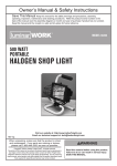
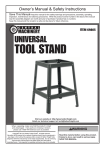
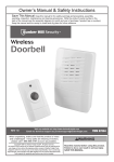
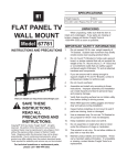
Table of Contents
Safety ......................................................... 2
Specifications ............................................. 3
Installation .................................................. 4
Parts List and Diagram ............................... 7
Warranty ..................................................... 8
SAFETy
WARNING SyMBoLS AND DEFINITIoNS
INSTALLATIoN
This is the safety alert symbol. It is used to alert you to potential
personal injury hazards. Obey all safety messages that
follow this symbol to avoid possible injury or death.
Indicates a hazardous situation which, if not avoided,
will result in death or serious injury.
Indicates a hazardous situation which, if not avoided,
could result in death or serious injury.
Indicates a hazardous situation which, if not avoided,
could result in minor or moderate injury.
Addresses practices not related to personal injury.
PARTS LIST
Page 2
For technical questions, please call 1-888-866-5797.
Item 61807
IMPoRTANT SAFETy INFoRMATIoN
Failure to heed these warnings may result in personal injury and/or property damage:
3. If unsure wall is strong enough to support
weight of TV and TV Wall Mount, contact a
professional installer to reinforce wall.
4. Do not mount overhead or to a non-vertical
surface. Mount parallel to the ground only.
5. Verify that mounting surface has no hidden
utility lines before drilling or driving screws.
6. Wear ANSI-approved safety goggles and
heavy-duty work gloves during installation.
7. Inspect before installing; do not mount to wall
if parts are missing, loose or damaged.
8. Assemble and install only according to
these instructions. Improper assembly and
installation can create hazards and lead to
personal injury and property damage.
10. Do not assemble or install when tired or when
under the influence of drugs or medication.
11. Weight capacity and other product capabilities apply
to properly and completely assembled product only.
SAFETy
2. Do not mount Wall Bracket (1) to hollow wall,
gypsum board, or similar material that will
not support the weight of the TV. Mount only
to 2″ x 4″ wood stud or concrete/brick walls
that can safely support combined weight
of Wall Bracket, Support Arms, TV and all
attached hardware and components.
9. Keep installation area clean and well lit.
12. Use as intended only. Do not use TV Wall Mount
for any purpose for which it was not designed.
13. This product is not a toy.
Do not allow children to play with or near this item.
14. Maintain product labels and nameplates.
These carry important safety information.
If unreadable or missing, contact
Harbor Freight Tools for a replacement.
15. The warnings, precautions, and instructions
discussed in this instruction manual cannot
cover all possible conditions and situations
that may occur. It must be understood by the
operator that common sense and caution are
factors which cannot be built into this product,
but must be supplied by the operator.
16. Carefully read TV instructions before
installation. Harbor Freight Tools is not
responsible for damage caused by failure to
follow TV mounting instructions, improper
installation, or improper/loose hardware.
INSTALLATIoN
1. Do not exceed listed weight capacity. Be aware of
dynamic loading! Sudden load movement may
briefly create excess load causing product failure.
SAVE THESE INSTRUCTIoNS.
Item 61807
Weight Capacity
176 lb
TV Size Range
37″ to 70″ diagonal
VESA Compliance
200 x 200 mm, 300 x 200 mm
300 x 300 mm, 400 x 200 mm
400 x 300 mm, 400 x 400 mm
600 x 400 mm, 800 x 400 mm
For technical questions, please call 1-888-866-5797.
PARTS LIST
Specifications
Page 3
Installation Instructions
Read the ENTIRE IMPoRTANT SAFETy INFoRMATIoN section at the beginning of this
manual including all text under subheadings therein before set up or use of this product.
SAFETy
Note: The following tools (not included) are required for mounting and installation: Stud Finder,
Phillips screwdriver, 5/32″ drill bit (for drilling into wood stud), 3/8″ carbide tip masonry drill bit
(for drilling into brick or concrete wall), minimum 6″ level, and wrench or socket set.
Attaching to Wood Studs
Note: The installation hardware included
with this unit is not suitable for use on steel
stud walls. If mounting to a steel stud wall,
alternative mounting hardware is required.
1. Verify wood studs are at least 16″ apart.
Use a Stud Finder (not included) to find two
adjacent studs 16″ apart. Use a marker
to indicate locations of the studs.
WARNING! Do not mount Wall Bracket to
drywall or plaster. Ensure that mounting
holes are located in wood studs.
4. Use four Lag Bolts (14) and Lag Bolt Washers (15)
to mount Wall Bracket to wall studs. Center
Bracket across mounting locations with mounting
holes flush against the wall. Refer to Figure A.
Wall Bracket (1)
WARNING! Verify that mounting surface has no
hidden utility lines before drilling or driving screws.
INSTALLATIoN
2. Set Wall Bracket (1) against the wall at the desired
height. Place a level over the upper or lower
cross bar and adjust Bracket until level. Use a
marker to indicate locations of mounting holes.
3. Drill four 5/32″ holes at least 2-1/2″ deep
into the studs at the marked locations.
Lag
Bolt
(14)
Lag Bolt
Washer (15)
Figure A
Attaching to Brick or Concrete Wall
Note: The installation hardware included
with this unit is not suitable for use on cinder
block walls. If mounting to a cinder block wall,
alternative mounting hardware is required.
Wall Bracket (1)
1. Set Wall Bracket against the wall at the desired
height. Place a level over the upper or lower cross
bar and adjust Bracket until level. Use a marker
to indicate locations of mounting holes, two in
the top row of slots and two in the bottom. Allow
at least 6″ of space between any two holes.
2. Use a 3/8″ carbide tip masonry drill bit and drill four
holes at least 2-1/2″ deep at the marked locations.
PARTS LIST
3. Insert the Concrete Wall Anchors (16) into the holes,
making sure they are flush with the wall surface.
WARNING! Concrete Wall Anchors must be
set firmly into concrete or masonry. If mounting
to a masonry wall covered with drywall/plaster,
counter bore a hole through drywall/plaster around
mounting hole locations. See Figures B and C.
Concrete
Lag
Bolt
(14)
Lag Bolt
Washer
(15)
Concrete Wall
Anchor (16)
Figure B
Wall
Bracket
(1)
Concrete
Lag
Bolt
(14)
Lag Bolt
Washer
(15)
Plaster/
Drywall
Concrete Wall
Anchor (16)
Figure C
Page 4
For technical questions, please call 1-888-866-5797.
Item 61807
4. Once Wall Anchors are securely set into concrete,
use four Lag Bolts and Lag Bolt Washers to
install Wall Bracket to wall. Center Bracket
across mounting locations with mounting holes
flush against the wall. Refer to Figure D.
Lag Bolt
(14)
Wall
Anchor
(16)
Lag Bolt
Washer (15)
Figure D
SAFETy
Wall Bracket
(1)
Installing Support Arms to Flat Panel TV
Read TV owner’s manual before attaching
this product. Some TV’s will be damaged or
cause a risk of electric shock if screws are
threaded in too deeply. Harbor Freight Tools is
not responsible for damage caused by failure
to follow TV mounting instructions, improper
installation, or improper/loose hardware.
Note: If none of the Screws supplied are an
appropriate size, refer to TV owner’s manual or
contact TV manufacturer.
1. Unplug TV before threading any
Screw into the TV’s back panel.
Screws (3-6)
Washer (11-12)
2. Do not lay flat panel TV face down to install
Support Arms. Cover TV screen with a
towel or other soft material and tilt it against
the wall or another solid surface.
3. Locate the mounting holes on back of TV
and select mounting Screws (3, 4, 5 or 6)
that fit properly. If the TV included mounting
screws, use those screws instead.
Lock Washer
(7-10)
Spacer
(13)
Support
Arms
(2a, 2b)
TV Back
4. Thread the Screws through the matching Lock
Washers (7, 8, 9 or 10), matching Washers
(11 or 12), the Support Arms (2a, 2b), and
into the mounting holes in the back of TV
panel. Use the Spacers (13) positioned as
shown if the bolts are too long or if the back
of the TV is not flat. Refer to Figure E.
INSTALLATIoN
5. Torque Screws to the specification listed in
the TV owner’s manual to prevent loosening.
Do not overtighten to avoid TV damage.
Figure E
Adjusting Flat Panel TV Angle Before Installation
2. Tilt the Hook Brackets on the Support Arms to the
desired angle (angle is adjustable from 0° to 12°).
Ensure that both Hook Brackets are set at the
same angle and tighten the Angle Adjusting Screws
all the way to lock the angle position.
Refer to Figure F.
Angle
Adjusting
Screw
Angle
Adjusting
Screw
Hook
Bracket
Support
Arms
Figure F
Item 61807
For technical questions, please call 1-888-866-5797.
Page 5
PARTS LIST
1. To adjust the TV angle before mounting
to Wall Bracket, loosen the two Angle
Adjusting Screws located at the sides of
the Support Arms by several turns.
Hook
Bracket
Installation Instructions (continued)
Mounting Flat Panel TV to Wall Bracket
SAFETy
WARNING! Some Flat Panel TVs may require
two people to lift and support the TV while it
is being attached to the Wall Bracket.
2. Carefully rotate the TV toward the wall until
the Support Arms engage the bottom of
the Wall Bracket. Refer to Figure G.
1. Carry TV with attached Support Arms to mounted
Wall Bracket and lower onto top cross bar,
making sure both Hook Brackets on the Support
Arms are hooked onto the top of cross bar
and that TV is centered. Refer to Figure G.
3. Tighten the two Clamping Screws on the bottom
of the Support Arms to secure the TV/Support Arm
assembly to the Wall Bracket. Refer to Figure H.
4. Carefully make sure that the Support Arms are
completely attached to the Wall Bracket, both
at their top and bottom, before releasing TV.
Support
Arm
Support
Arm
Hook
Bracket
Hook
Bracket
INSTALLATIoN
Wall
Bracket
Wall
Bracket
Wall
Clamping
Screw
Wall
Figure G
Figure H
Adjusting Flat Panel TV Angle When Installed
1. To adjust the angle when the TV is
already mounted to Wall Bracket, use the
following procedure to remove the TV from
the Bracket and adjust the angle:
a. Unplug the TV.
PARTS LIST
b. Loosen the two Clamping Screws on the
bottom of the Support Arms until the bottom
of the TV/Support Arm assembly can be tilted
forward to disengage the Wall Bracket.
c. Carefully lift the TV/Support Arm
assembly up slightly and off of the Wall
Bracket. Refer to Figures G and H.
Page 6
WARNING! Some Flat Panel TVs may require
two people to lift and support the TV while it
is being removed from the Wall Bracket.
d. Cover TV screen with a towel or other soft
material and tilt it against the wall or another
solid surface, then follow steps 1 and 2
in Adjusting Flat Panel TV Angle Before
Installation section to adjust angle.
e. Once desired angle is set, remount TV to Wall
Bracket following steps 1 through 4 in Mounting
Flat Panel TV to Wall Bracket section.
For technical questions, please call 1-888-866-5797.
Item 61807
Parts List and Diagram
THE MANUFACTURER AND/OR DISTRIBUTOR HAS PROVIDED THE PARTS LIST AND ASSEMBLY DIAGRAM
IN THIS MANUAL AS A REFERENCE TOOL ONLY. NEITHER THE MANUFACTURER OR DISTRIBUTOR
MAKES ANY REPRESENTATION OR WARRANTY OF ANY KIND TO THE BUYER THAT HE OR SHE IS
QUALIFIED TO MAKE ANY REPAIRS TO THE PRODUCT, OR THAT HE OR SHE IS QUALIFIED TO REPLACE
ANY PARTS OF THE PRODUCT. IN FACT, THE MANUFACTURER AND/OR DISTRIBUTOR EXPRESSLY
STATES THAT ALL REPAIRS AND PARTS REPLACEMENTS SHOULD BE UNDERTAKEN BY CERTIFIED AND
LICENSED TECHNICIANS, AND NOT BY THE BUYER. THE BUYER ASSUMES ALL RISK AND LIABILITY
ARISING OUT OF HIS OR HER REPAIRS TO THE ORIGINAL PRODUCT OR REPLACEMENT PARTS
THERETO, OR ARISING OUT OF HIS OR HER INSTALLATION OF REPLACEMENT PARTS THERETO.
Description
Qty
Wall Bracket
Left Support Arm
Right Support Arm
Screw M4 x 20
Screw M5 x 20
Screw M6 x 20
Screw M8 x 20
Lock Washer M4
Lock Washer M5
1
1
1
4
4
4
4
4
4
Part
9
10
11
12
13
14
15
16
Description
Qty
Lock Washer M6
Lock Washer M8
Washer M4/M5
Washer M6/M8
Spacer
Lag Bolt
Lag Bolt Washer
Concrete Wall Anchor
1
2a
4
4
4
4
4
4
4
4
INSTALLATIoN
1
2a
2b
3
4
5
6
7
8
2b
3
4
5
6
7
8
9
10
11
12
13
14
15
16
PARTS LIST
Part
Record Product’s Serial Number Here:
Note: If product has no serial number, record month and year of purchase instead.
Note: Some parts are listed and shown for illustration purposes only,
and are not available individually as replacement parts.
Item 61807
For technical questions, please call 1-888-866-5797.
SAFETy
PLEASE READ THE FoLLoWING CAREFULLy
Page 7
Limited 90 Day Warranty
Harbor Freight Tools Co. makes every effort to assure that its products meet high quality and durability standards,
and warrants to the original purchaser that this product is free from defects in materials and workmanship for the
period of 90 days from the date of purchase. This warranty does not apply to damage due directly or indirectly,
to misuse, abuse, negligence or accidents, repairs or alterations outside our facilities, criminal activity, improper
installation, normal wear and tear, or to lack of maintenance. We shall in no event be liable for death, injuries
to persons or property, or for incidental, contingent, special or consequential damages arising from the use of
our product. Some states do not allow the exclusion or limitation of incidental or consequential damages, so the
above limitation of exclusion may not apply to you. THIS WARRANTY IS EXPRESSLY IN LIEU OF ALL OTHER
WARRANTIES, EXPRESS OR IMPLIED, INCLUDING THE WARRANTIES OF MERCHANTABILITY AND FITNESS.
To take advantage of this warranty, the product or part must be returned to us with transportation charges
prepaid. Proof of purchase date and an explanation of the complaint must accompany the merchandise.
If our inspection verifies the defect, we will either repair or replace the product at our election or we may
elect to refund the purchase price if we cannot readily and quickly provide you with a replacement. We will
return repaired products at our expense, but if we determine there is no defect, or that the defect resulted
from causes not within the scope of our warranty, then you must bear the cost of returning the product.
This warranty gives you specific legal rights and you may also have other rights which vary from state to state.
3491 Mission oaks Blvd. • Po Box 6009 • Camarillo, CA 93011 • 1-888-866-5797