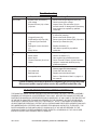
1
® Fuel transfer pump 12vdc 98135 Set up And Operating Instructions Distributed exclusively by Harbor Freight Tools®. 3491 Mission Oaks Blvd., Camarillo, CA 93011 Visit our website at: http://www.harborfreight.com Read this material before using this product. Failure to do so can result in serious injury. Save this manual. Copyright© 2008 by Harbor Freight Tools®. All rights reserved. No portion of this manual or any artwork contained herein may be reproduced in any shape or form without the express written consent of Harbor Freight Tools. Diagrams within this manual may not be drawn proportionally. Due to continuing improvements, actual product may differ slightly from the product described herein. For technical questions or replacement parts, please call 1-800-444-3353. Save This Manual NOTICE is used to address practices not related to personal injury. Keep this manual for the safety warnings and precautions, assembly, operating, inspection, maintenance and cleaning procedures. Write the product’s serial number in the back of the manual near the assembly diagram (or month and year of purchase if product has no number). Keep this manual and the receipt in a safe and dry place for future reference. CAUTION, without the safety alert symbol, is used to address practices not related to personal injury. WARNING ! R e a d a l l i n s t r u c t i o n s Failure to follow all instructions listed below may result in fire, explosion and/or serious injury. Important SAFETY Information In this manual, on the labeling, and all other information provided with this product: SAVE THESE INSTRUCTIONS Installation safety 1. This is the safety alert symbol. It is used to alert you to potential personal injury hazards. Obey all safety messages that follow this symbol to avoid possible injury or death. When connecting this Fuel Transfer Pump to a 12 Volt DC battery or power source, connect the negative wire, the positive wire and the ground wire. All three need to be connected securely before using this Pump. 2. DANGER indicates a hazardous situation which, if not avoided, will result in death or serious injury. Install the Fuel Pump according to the instructions in this manual. A risk of explosion may be created if some instructions are not followed. 3. This Fuel Transfer Pump has a builtin Check Valve Assembly (27) with pressure relief to prevent fluid ther mal expansion from causing unsafe system pressure. DO NOT install additional check valves or foot valves during installation without proper relief valves built into them. Product damage may result. 4. Keep work area clean and well lit. Cluttered or dark areas invite acci dents. WARNING indicates a hazardous situation which, if not avoided, could result in death or serious injury. CAUTION, used with the safety alert symbol, indicates a hazardous situation which, if not avoided, could result in minor or moderate injury. SKU 98135 For technical questions, please call 1-800-444-3353. Page 2 5. Use safety equipment. Wear ANSIapproved safety goggles, a dust mask/respirator (for fumes), and nonskid safety shoes during installation. General/Operation Safety 1. DO NOT SMOKE while using this Fuel Transfer Pump. DO NOT use this pump near pilot lights, open flame, or sparks. 2. Keep multiple class ABC fire extinguishers nearby. 3. Before use, make sure to ground the Nozzle (54) to the neck of the tank/container being filled with fuel at all times. This will help prevent buildup of static electricity which can spark causing fire, and/or explosion and serious bodily injury or death. 4. Keep children and bystanders away while installing, operating, or maintaining this Fuel Transfer Pump. 5. Stay alert, watch what you are doing and use common sense when operating. Do not use while you are tired or under the influence of drugs, alcohol or medication. A moment of inattention while operating may result in serious personal injury. 6. Do not leave this Fuel Transfer Pump unattended while it is operating. Do not lock the Fuel Nozzle in open position. 7. This Fuel Transfer Pump is not a toy. DO NOT allow children to operate it. 8. Do not wear clothing made from synthetic fibers. There is danger from static electricity build up causing SKU 98135 sparks that could lead to fire or explosion. 9. Place empty containers on flat level ground before filling. 10. Use this Fuel Transfer Pump outdoors only. 11. DO NOT pump from or into a vehicle that is running. Turn off engine of fueled vehicle (and fueling vehicle) before hooking up nozzle or starting to pump. 12. Follow all local and state laws governing use of Fuel Pumps. 13. This Fuel Transfer Pump should only be used for one fluid. This will ensure that different fluids will not contaminate one another and help to prevent unexpected reactions. 14. WARNING: This product contains or, when used, produces a chemical known to the State of California to cause cancer and birth defects or other reproductive harm. (California Health & Safety Code § 25249.5, et seq.) 15. WARNING: The brass components of this product contain lead, a chemical known to the State of California to cause birth defects (or other reproductive harm). (California Health & Safety Code § 25249.5, et seq.) 16. The warnings, precautions, and instructions discussed in this instruction manual cannot cover all possible conditions and situations that may occur. It must be understood by the operator that common sense and caution are factors which cannot be built into this For technical questions, please call 1-800-444-3353. Page 3 product, but must be supplied by the operator. Maintenance Safety 1. Have your equipment serviced by a qualified repair person using only identical replacement parts. This will ensure that the safety of the equipment is maintained. 2. Maintain labels and nameplates on the pump. These carry important safety information. If unreadable or missing, contact Harbor Freight Tools for a replacement. Save these instructions. Specifications Permanent Magnetic Motor pumps diesel, Kerosene, Light weight oils, water and antifreeze* Up to 10 Gallons Per Minute Application Flow Duty Cycle Continuous Voltage Required 12 VDC, 23.5 A * Not for use with fluids that have a flashpoint below 100° F/38° C Unpacking When unpacking, check to make sure that the item is intact and undamaged. If any parts are missing or broken, please call Harbor Freight Tools at the number shown on the cover of this manual as soon as possible. REV 08h SKU 98135 For technical questions, please call 1-800-444-3353. Page 4 Initial Set Up Instructions Read the entire Important Safety Information section at the beginning of this manual including all text under subheadings therein before set up or use of this product. barrel, or drum. When installed, attach parts as in steps two and three. 5. Functions 1. This Fuel Transfer Pump is compatible and may be used with the following fluids: Diesel, Kerosene, light weight oils, water and antifreeze. This Pump IS NOT compatible with, and should NEVER be used to pump: Acetone, Gasoline, Ammonia, Lacquer Thinner, Benzene, Bleach, Hydrochloric Acid, Ink or Toluene. NOTE: No other fluids should be used, but the “incompatible” fluids listed above can be especially dangerous. Not for use with fluids that have a flashpoint below 100°F/38°C. 2. Once used with a specific type of fluid, continue to use ONLY that fluid with this Pump (except for diesel flushing for storage). Using another fluid may lead to contamination or reaction between the fluids. To prevent serious injury from accidental operation: Turn the Power Switch of the pump to its “OFF” position and disconnect from power source before assembling or making any adjustments to the pump. Note: For additional information regarding the parts listed in the following pages, refer to the Assembly Diagram near the end of this manual. Wrench tighten all connections. Assembly Note:Use a gasoline- and oil-proof pipe compound (not supplied) on all joints. General Installation and Connection Instructions 1. Thread male end of Steel Elbow (39) into the Pump Housing (1). Tighten securely at this point. 1. 2. Thread end of Hose (55) into female end of Steel Elbow (39). DO NOT tighten securely. Keep work area clean and well lit. Cluttered or dark areas invite accidents. 2. 3. Thread Nozzle (54) to Hose (55). DO NOT tighten securely. Use safety equipment. Always wear ANSI-approved safety goggles. Safety equipment such as dust mask/respirator (for fumes), and non-skid safety shoes. 4. After making sure connections will fit, remove parts attached in step two and three until after Fuel Transfer Pump has been installed on tank, 3. This Fuel Transfer Pump has a builtin Check Valve Assembly (27) with pressure relief to prevent fluid thermal expansion from causing unsafe REV 08h SKU 98135 For technical questions, please call 1-800-444-3353. Page 5 system pressure. DO NOT install additional check valves or foot valves during installation without proper relief valves built into them. 4. 5. 6. Make sure to connect the Ground Wire (51). 6. Systems should be set up requiring a minimum amount of suction lift. The maximum vertical distance from the surface of the fuel inside the tank to the inlet of the Pump is 9 feet for gas and 10 feet for diesel. 1. A water separator (not supplied) should be used if you are going to pump diesel fuel. DO NOT attempt to connect and power this pump to thin wiring from cigarette lighter. 2. NOTE: The Ground Wire (51) must always be independently connected to the frame or chassis of vehicle and/or container being fueled, or filled. For example, DO NOT connect green and black wires together. Unless the Fuel Transfer Pump and the fuel tank, barrel or drum are grounded to one another, sparking due to a static charge or wiring faults could possibly ignite fumes resulting in an explosion. 3. If this Fuel Transfer Pump is to be powered from a vehicle power system, it is recommended that permanent wiring and connections be made to the vehicle power system and include a 30 amp, slow blow fuse. Attaching Fuel Transfer Pump to a Vehicle A filter (not supplied) should be used at Pump outlet to insure that no foreign material is transferred to fuel tanks. Attaching Fuel Transfer Pump to Tank or Barrel 1. 2. The tank, barrel or drum should be securely anchored to prevent accidental movement or tipping. Tightly thread Suction Pipe (58) into the inlet flange (24) at the base of the Pump Housing (1). Thread the Suction Pipe Extension (59) to Suction Pipe (58). Using a hack saw (not supplied), cut the Suction Pipe Extension (59) to a length within 3” of the bottom of the tank, barrel or drum. DO NOT rest the Suction Pipe Extension (59) on the bottom. 3. Screw the Inlet Flange (24) completely and securely into the tank, barrel or drum opening. 4. Install the Hose (55) and Nozzle (54) See “Assembly Instructions” on page 6 of this manual. 5. Connect the Cable (60) that extends from the Cable Connector (53). SKU 98135 Connecting Fuel Transfer Pump 1. Remove the Junction Box Cover (18) from the Motor Casing Assembly (6) and straighten wires to make the stripped wire ends accessible. 2. Screw the furnished Cable Connector (53) into the Conduit Opening of the Motor Casing Assembly (6). For technical questions, please call 1-800-444-3353. Page 6 3. Strip 6” of the outer insulation covering the Cable (60) being careful not to damage the wire insulation. 4. Pass the stripped end of the Cable (60) through the Cable Connector (53) until 2” of the unstripped wire is within the Motor Casing Assembly (6). 5. Strip 1/2” of the insulation from the ends of the Cable (60). Connect these wires to the matching colored Pump Wires using wire nuts (not supplied). 6. Fold all wires into the Motor Casing assembly (6) and replace the Junction Box Cover (18). Make sure all screws are seated so there is no space between the Junction Box Cover (18) and the Motor Casing Assembly (6). 7. Run the Cable (60) to the 12 Volt DC battery or similar power source. Support the Cable (60) as necessary and protect it from heat, sharp edges or any other obstacle that could damage it. 8. Strip the outer Cable (60) covering as necessary. Make a secure connection to the tank, barrel, drum or vehicle with the Ground Wire (51). 9. NOTE: To determine if a vehicle system is negative (-) or positive (+), check the battery marking of the terminal that is wired to the vehicles frame or motor block. For vehicles with negative (-) ground, connect the negative (black) wire to the vehicle frame. For vehicles with positive (+) ground, connect the positive (red) wire to the vehicle frame. SKU 98135 10. If attaching to a vehicle, attach one end of a 30 amp fuse holder to the end of the remaining wire. Connect the other end of the fuse holder to the ungrounded side of the power source. The battery terminal or the end of the battery cable is recommended. 11. Check all connections to make sure they are correct. Install the 30 amp fuse in the fuse holder. For technical questions, please call 1-800-444-3353. Page 7 Operation This Fuel Transfer Pump must be set up according to all “Installation and Connection” information on pages 6 thru 8 of this manual. To reduce build up of static electricity and possible fire and/or explosion, do not wear synthetic fibers while using this Fuel Transfer Pump. 1. Maintain nozzle contact with neck of container being filled to reduce static electricity buildup. 2. On initial start-up it may be necessary to hold the Nozzle (54) open a few seconds to allow pump to prime. 3. Remove Nozzle (54) from Pump and insert into neck of tank, barrel, drum or fuel cell. 4. Begin fueling by squeezing lever on nozzle (54). 5. WARNING: The Pump Motor is equipped with thermal overload protection. If overheated, it will shut itself off without any damage to the electrical system. Be sure to turn off the Pump power if this occurs. As the Motor cools, it will start without warning if the power is left on. SKU 98135 For technical questions, please call 1-800-444-3353. Page 8 Maintenance And Servicing Procedures not specifically explained in this manual must be performed only by a qualified technician. To prevent serious injury from accidental operation: Turn OFF the power to the Fuel Transfer Pump before any inspection or maintenance is performed. 4. To keep Fuel Transfer Pump running at its best, flush with diesel fuel if it is to be stored for long periods of time. 5. Remove and clean Screen (25) after every 20 hours of continuous operation. Cleaning frequency depends on the type and cleanliness of fluids being pumped. 6. For safety reasons, service and maintenance should be performed regularly by a qualified technician. To prevent serious injury from Pump failure: Do not use damaged equipment. If abnormal noise, vibration, or leakage occurs, have the problem corrected before further use. Cleaning, Maintenance, and Lubrication 1. BEFORE EACH USE, inspect the general condition of the Pump. Check for loose screws, loose or broken electrical wiring, and any other condition that may affect its safe operation. 2. Maintain labels and nameplates on the pump. These carry important safety information. If unreadable or missing, contact Harbor Freight Tools for a replacement. 3. After Use, clean external surfaces of the Pump with clean cloth. SKU 98135 For technical questions, please call 1-800-444-3353. Page 9 Troubleshooting Problem Pump will not prime Possible Causes 1. Suction Pipe (58) leak. 2. Bypass Valve (28) open. 3. Vanes (33) sticking. 4. Inlet Gasket (26) leakage. 5. Excessive Rotor (34) or Vane (33) wear. 6. Motor not operating. 7. Motor is running backwards. Likely Solutions 1. Check for leaks in Suction Pipe (58). 2. Remove and inspect Bypass Valve (28). 3. Check Vanes (33) and slots for nicks, burrs, wear, and accumulation. 4. Check and tighten all covers and joints. 5. Check Rotor (34) and Vanes (33) for excessive wear or possible damage. 6. Motor Rotor (34) should turn clockwise at Pump end; if not, have it repaired by a qualified technician. 7. Check all wiring for correct polarity. Pump hums but will not operate 1. Dirt in Pump cavity. 2. Motor failure. 1. Clean out Pump cavity. 2. Motor bearing(s) (2) possibly frozen. Have Motor repaired by qualified technician. Low Capacity 1. Excessive dirt in Screen (25). 2. Suction Pipe (58) Problem. 1. Remove and clean Screen (25). 2. Check Suction Pipe (58) for leaks or restrictions. 3. Remove and inspect Bypass Valve (28) 4. Check Vanes (33) and slots for wear or deposits. 5. Check Rotor (34 and Vanes (33) for excessive wear or damage. 6. Replace Hose (55) (DO NOT REPAIR) 3. Bypass Valve (28) sticking. 4. Vanes (33) sticking. 5. Excessive Rotor (34) or Vane (33) wear. 6. Hose (55) damage. Pump runs slowly 1. Incorrect voltage. 2. Vanes (33) sticking. 3. Wiring problem. 4. Motor Casting Assembly (6) out of line. 5. Brush problem. 6. Motor problem. 7. Motor failure. 1. Check incoming line voltage. 2. Check Vanes (33) and slots for wear. 3. Check for loose or broken wiring and replace if damage is found. 4. Motor frame must be installed with punch mark in line with notch in Motor Casting Assembly (6). 5. Check Brushes for excessive wear and adequate spring tension. Have repaired or replaced by qualified technician. 6. Inspect armature and commutator and repair or replace if necessary. Have work done by a qualified technician. 7. Motor bearing(s) (2) failing. Have repaired by qualified technician. Follow all safety precautions whenever diagnosing or servicing the pump. Disconnect power supply before service by qualified technician only. SKU 98135 For technical questions, please call 1-800-444-3353. Page 10 Troubleshooting Problem Possible Causes Likely Solutions Motor Stalls 1. Bypass Valve (28) sticking 2. Low voltage. 3. Excessive Rotor (34) or Vane (33) wear. 1. Remove and inspect Bypass Valve (28). 2. Check incoming line voltage. 3. Inspect Rotor (34) and Vanes (33) for excessive wear or damage and if necessary, have replaced or repaired by qualified technician. Motor overheats 1. Pumping high viscosity fluids. 1. Pump may need to rest 5 minutes after every 5 minutes of pumping. 2. Remove and clean Screen (25). 3. Remove and clean Suction Pipe (58) and/or Suction Pipe Extension (59). 2. Clogged Screen (25). 3. Restricted Suction Pipe (58), or Suction Pipe Extension (59). 4. Damaged, or worn Armature (3). 5. Motor failure. 4. Replace Armature (3). 5. Have Motor repaired by a qualified technician. Motor will not turn on 1. No Power. 2. Switch failure. 3. Motor failure. 4. Thermal Protector (8) or fuse failure. 1. Check incoming power source. 2. Check Line Switch (17). 3. Have repaired by qualified technician. 4. Check Thermal Protector (8) and fuse and replace if needed with identical part by qualified technician. Fluid leakage 1. Bad O-Ring or Gasket. 1. Check all O-Rings and Gaskets. (See Parts List on page 12 of this manual.) 2. Clean seal and seal cavity. 3. Replace seal with identical part. 4. Refer to “Specification Chart” on page 3 of this manual. 2. Dirty shaft seal. 3. Bad shaft seal. 4. Incompatible fluid. Follow all safety precautions whenever diagnosing or servicing the pump. Disconnect power supply before service by qualified technician only. PLEASE READ THE FOLLOWING CAREFULLY The manufacturer and/or distributor has provided the parts list and assembly diagram in this manual as a reference tool only. Neither the manufacturer or distributor makes any representation or warranty of any kind to the buyer that he or she is qualified to make any repairs to the product, or that he or she is qualified to replace any parts of the product. In fact, the manufacturer and/ or distributor expressly states that all repairs and parts replacements should be undertaken by certified and licensed technicians, and not by the buyer. The buyer assumes all risk and liability arising out of his or her repairs to the original product or replacement parts thereto, or arising out of his or her installation of replacement parts thereto. SKU 98135 For technical questions, please call 1-800-444-3353. Page 11 PARTS LIST Part Description Q’ty Part PARTS LIST Description Q’ty 1 Pump Housing 1 31 Bypass Cap 1 2 Ball Bearing 2 32 1/4-20 X 3/4” HHCS 4 3 Armature Assembly 1 33 Vane(s) 5 4 Motor Frame/Magnet Assembly 1 34 Rotor 1 5 1/4-20 X 5” Thru-Bolt 2 35 Rotor Key 1 6 Motor Casting Assembly 1 36 Rotor Cover 1 7 Switch Plate with Bushing 1 37 Rotor Cover Gasket 1 8 Thermal Protector 1 38 Seal Assembly 1 9 Brush Holder Assembly 2 39 Steel Elbow 1 10 Negative Brush Assembly 1 40 5/16-18 X 3/4” HHCS 2 11 #8-32 X 1/2” Star Screw 1 41 Nozzle Cover 1 13 #8-32 X 3/8” Star Screw 2 42 Switch Lever 1 14 5/16” Spring Washer 1 43 5/15 X 18 Locknut 1 15 Switch Shaft Assembly 1 44 #14 X 5/8” Driver Screw 1 16 Positive Brush Assembly 1 45 Locking Link 1 17 Line Switch 1 46 1/4” Spring Washer 2 18 Junction Box Cover 1 49 5/16” Retaining Ring 1 19 Negative Wire Lead 1 51 Ground Wire (Green/White) 1 20 Positive Wire Lead 1 52 #8-32 X 3/8” Ground Screw 1 22 10-24 X 3/4” Star Screw 6 53 Cable Connector 1 23 5/32 X 1/2” Pin 1 54 Nozzle 1 24 Inlet Flange 1 55 Hose 1 25 Screen 1 56 10-24 X .50 Star Screw 4 26 Inlet Gasket 1 57 1/4-20 X .5 HHCS 4 27 Check Valve Assembly 1 58 Suction Pipe 1 28 Bypass Valve 1 59 Suction Pipe Extension 2 29 Bypass Valve Gasket 1 60 Cable (not shown) 1 30 Bypass Spring 1 SKU 98135 For technical questions, please call 1-800-444-3353. Page 12 ASSEMBLY DIAGRAM Record Product’s Serial Number Here: Note: If product has no serial number, record month and year of purchase instead. Note: Some parts are listed and shown for illustration purposes only, and are not available individually as replacement parts. SKU 98135 For technical questions, please call 1-800-444-3353. Page 13 Limited 1 year / 90 day Warranty Harbor Freight Tools Co. makes every effort to assure that its products meet high quality and durability standards, and warrants to the original purchaser that for a period of one year from date of purchase that the tank is free of defects in materials and workmanship (90 days if used by a professional contractor or if used as rental equipment). Harbor Freight Tools also warrants to the original purchaser, for a period of ninety days from date of purchase, that all other parts and components of the product are free from defects in materials and workmanship. This warranty does not apply to damage due directly or indirectly to misuse, abuse, negligence or accidents, repairs or alterations outside our facilities, normal wear and tear, or to lack of maintenance. We shall in no event be liable for death, injuries to persons or property, or for incidental, contingent, special or consequential damages arising from the use of our product. Some states do not allow the exclusion or limitation of incidental or consequential damages, so the above limitation of exclusion may not apply to you. This warranty is expressly in lieu of all other warranties, express or implied, including the warranties of merchantability and fitness. To take advantage of this warranty, the product or part must be returned to us with transportation charges prepaid. Proof of purchase date and an explanation of the complaint must accompany the merchandise. If our inspection verifies the defect, we will either repair or replace the product at our election or we may elect to refund the purchase price if we cannot readily and quickly provide you with a replacement. We will return repaired products at our expense, but if we determine there is no defect, or that the defect resulted from causes not within the scope of our warranty, then you must bear the cost of returning the product. This warranty gives you specific legal rights and you may also have other rights which vary from state to state. 3491 Mission Oaks Blvd. • PO Box 6009 • Camarillo, CA 93011 • (800) 444-3353 SKU 98135 For technical questions, please call 1-800-444-3353. Page 14