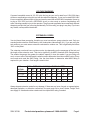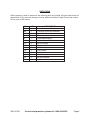
1
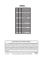
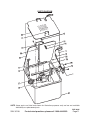
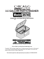
3.5 GALLON PARTS WASHER
Assembly and Operating Instructions
®
3491 Mission Oaks Blvd., Camarillo, CA 93011
Visit our Web site at http://www.harborfreight.com
Copyright® 1997 by Harbor Freight Tools®. All rights reserved. No portion of this manual
or any artwork contained herein may be reproduced in any shape or form without the
express written consent of Harbor Freight Tools.
For technical questions and replacement parts, please call 1-800-444-3353.
SPECIFICATIONS
Characteristic
Tank Dimensions
Max. Solvent Capacity
Pump Output
Electrical Requirements
Weight
Value
17-3/8" x 14-1/4" x 8-3/4"
3-1/2 Gallons
50 GPH
.7 Amps @ 110V, 60Hz
15-1/2 lbs.
SAVE THIS MANUAL
You will need the manual for the safety warnings and
READ ALL INSTRUCTIONS
cautions, assembly instructions, operating procedures,
BEFORE ASSEMBLING OR
maintenance procedures, trouble shooting, parts list, and
OPERATING THIS TOOL.
diagram. Keep your invoice with this manual. Write the
invoice number on the inside of the front cover. Keep both this manual and your invoice in a
safe, dry place for future reference.
SAFETY WARNING & CAUTIONS
WARNING: When using electric tools, machines, or equipment, basic safety precautions should
always be followed to reduce the risk of fire, electric shock, and personal injury. READ ALL
INSTRUCTIONS BEFORE USING THIS TOOL!
1.
2.
3.
4.
5.
6.
7.
KEEP WORK AREA CLEAN. Cluttered areas invite injuries.
KEEP CHILDREN AWAY. All children should be kept away from the work area. Don’t let
them handle tool.
DO NOT OPERATE THE PARTS WASHER IF UNDER THE INFLUENCE OF ALCOHOL
OR DRUGS. Read warning labels on prescriptions to determine if your judgment or
reflexes are impaired while taking drugs. If there is any doubt, do not attempt to operate.
READ ALL INFORMATION CONCERNING THE SOLVENT YOU ARE USING. Do not
use solvents with a flashpoint of less than 150°. Biodegradable solvents are recommended
as the use of mineral solvents or petroleum based solvents will cause premature pump
wear. Chlorinated solvents, e.g. 1-1-1 Trichloroethane and Methylene Chloride (also known
as methyl chloride) can chemically react with aluminum and may explode so are strictly
prohibited as this tool contain aluminum. If you are in any doubt whatsoever, contact the
solvent manufacturer.
DO NOT USE OR STORE NEAR OPEN FLAMES, PILOT LIGHTS IN STOVES OR
HEATERS, OR ANY OTHER HEAT SOURCE. Solvents are highly flammable. Always
make sure there is adequate ventilation. Extinguish all cigarettes when cleaning. Industrial
applications must follow OSHA requirements.
DO NOT OVERFILL THE PARTS WASHER. Do not fill above the level of the parts tray or
serious injury may occur.
MATERIALS USED WHEN CLEANING MAY BE HARMFUL OR FATAL IF INHALED
AND/OR SWALLOWED. Once again, when using the tool, always make sure there is
adequate ventilation. Always use a mask or respirator when close to fumes.
REV 05/05;06/05
SKU 35740
For technical questions, please call 1-800-444-3353.
Page 2
8.
9.
10.
11.
12.
13.
14.
15.
16.
17.
USE EYE PROTECTION. Solvents can cause serious eye damage . Wear ANSI approved
chemical splash safety goggles. Goggles are available from Harbor Freight Tools. When
cleaning, be especially careful as solvents can be forcibly ejected from fluid and air
passages.
DRESS SAFELY. Protective gloves and nonskid footwear or safety shoes must be used
when working with and operating the Parts Washer. Don’t wear loose clothing or jewelry.
They can get caught in moving parts. Also, wear a protective hair covering to prevent long
hair from getting caught in the Parts Washer.
DON’T OVERREACH. Keep proper footing and balance at all times.
STAY ALERT. Watch what you are doing. Use common sense. Do not operate any tool
when you are tired.
CHECK DAMAGED PARTS. Before using any tool, any part that is damaged should be
carefully checked to determine that it will operate properly and perform its intended function.
Check for alignment of moving parts, breakage of parts, and other conditions that may
affect its operation.
REPLACEMENT PARTS AND ACCESSORIES. When servicing, use only identical
replacement parts. Only use accessories intended for use with this Parts Washer.
Approved accessories are available from Harbor Freight Tools.
STORE IDLE EQUIPMENT. When not in use, the Parts Washer should be cleaned and
then stored, fully assembled, in a dry location to reduce rust. For safety, keep out of reach
of children.
MAINTAIN TOOLS WITH CARE. Keep tools clean for better and safer performance.
Follow instructions for lubricating, cleaning and changing accessories. Keep handles dry,
clean and free from oil and grease.
OUTDOOR EXTENSION CORDS. When the Parts Washer is used outdoors, use only
rounded jacket extensions cords intended for outside use. See manufacturer’s manual for
the AWG required for the compressor’s amperage draw. Do not leave the Parts Washer
outside for extended periods of time.
DO NOT MODIFY OR JAM LID TO KEEP LOCKED IN AN OPEN POSITION. The lid is
on a fusible link and is designed to fall automatically to extinguish flames. If fire should
occur, do not attempt to move parts washer.
GROUNDING INSTRUCTIONS
1.
This machine has a three prong plug. The third prong (round) is the ground. Plug the
machine’s cord only into three-prong receptacles. Never cut off the round prong. Cutting off
the ground will result in a safety hazard and void the warranty.
2.
If a three-prong receptacle is not available, you may use an adapter. Extending from the
male end of the adapter, you will find a ring connector or wire lead with a ring connector
where the ground (round prong) would be. Remove the center screw of the outlet cover and
put the screw through the ring connector and back into the hole of the outlet cover. Do not
over tighten or you will crack the outlet cover.
SKU 35740
For technical questions, please call 1-800-444-3353.
Page 3
VOLTAGE WARNING
Common household current is 110-120 volts. As long as your tool is rated from 110V-120V there
will be no complications using this tool with household receptacles. If your tool is rated 220V-240V
it has a completely different style of plug and must be used with a 220V-240V receptacle. Never try
to plug a 110V-120V tool into a 220V-240V circuit (or vice-versa) or serious complications will
arise, including possible injury to the operator. The plugs and receptacle have completely different
shapes to prevent this from occurring accidentally. Do not modify your plug in any way. If you have
any doubts, call a qualified electrician.
EXTENSION CORDS
Your tool has a three prong plug, therefore you must use a three- prong extension cord. Only use
rounded jacket extension cords listed by the Underwriters Laboratories (UL). If you are using the
tool outdoors, you must use an extension cord rated for outdoor use. This is signified by the letters
“WA” on the jacket.
The extension cord must have a minimum wire size depending on the amperage of the tool and
the length of the extension cord. This size is signified by its AWG (American Wire Gauge) rating.
The smaller the gauge, the greater the cable’s capacity. It does not matter if you are using one
cord, or two or more- the total length is what is used to determine the minimum AWG rating. Every
cord used must meet the AWG rating. Use the chart below to determine what AWG rating is
required for your situation. Cord length is rated in feet.
AMP
TOTAL EXTENSION CORD(S) LENGTH IN FEET
RATING
25
50
75
100
125
150
175
200
0-10.0
10.1-13.0
18
16
18
16
16
14
16
14
14
14
14
12
12
12
12
12
A
W
13.1-15
14
14
12
12
12
12
12
__
G
15-18
14
12
12
12
12
12
__
__
Always inspect extension cords for any damage. If there are any loose, frayed, or exposed wires;
damaged insulation; or defective connections, the cord must not be used. Harbor Freight Tools
can supply UL listed and outdoor rated cords in multiple AWG rating if needed.
SKU 35740
For technical questions, please call 1-800-444-3353.
Page 4
UNPACKING
When unpacking, check to make sure the following parts are included. All sizes listed below are
approximate. If any parts are missing or broken, please call Harbor Freight Tools at the number
on the cover of this manual.
NO.
NA
NA
NA
7
9
10
12
13
14
19
20
21
22
23
SKU 35740
QTY.
1
1
1
1
1
1
2
2
2
1
3
3
3
3
DESCRIPTION
Parts Washer and Pump Assembly
Cord and Switch Box Assembly
Work Shelf Assembly
Filter
Flexible Metal Spigot
Lid Handle
M5 x 12 Screw
M5 Lock Washer
M5 Nut
Cord Clamp
M4 x 8 Screw
M4 Washer
M4 Lock Washer
M4 Nut
For technical questions, please call 1-800-444-3353.
Page 5
ASSEMBLY
Lid Handle Assembly
Step 1: Get out the LID HANDLE (#10); and two each of the SCREWS (#12), Lock Washers
(#13), and NUTS (#14).
Step 2: Attach HANDLE to LID (#2) as shown in Figure 1.
Lid
(#2)
Screw
(#12)
Handle
(#10)
Lock
Washer
(#13)
Nut
(#14)
Figure 1 — Attaching Handle to Lid
SKU 35740
For technical questions, please call 1-800-444-3353.
Page 6
Cord Clamp/Ground Wire Installation
Step 1: As viewed from the inside, insert one SCREW (#20) through the right side of the
CORD CLAMP (#19) and the inside of the TANK (#1). Make sure CORD CLAMP is
covering the cord of the PUMP (#6).
Step 2: On the outside of the TANK, put both ground wires (green with ring-ears) on the
SCREW. Secure using (in the following order) a LOCK WASHER (#22), WASHER
(#21), & NUT (#23).
Step 3: Leave the other side of the CORD CLAMP unattached for now.
Switch Box Wiring and Installation
White
Wire
Step 1: Make sure the black and white
wires from the POWER CORD
(#17) are hooked up to the bottom
terminals as shown in Figure 2.
Black
Wire
Step 2: Connect the black and white wires
from the PUMP (#6) to the top
terminals in the same fashion as Power Cord
#17
the ones from the POWER CORD
as shown in Figure 2.
Ground
(goes to tank)
Figure 2 — Wiring Switch Box
SKU 35740
For technical questions, please call 1-800-444-3353.
Page 7
Step 3:
Attach the SWITCH BOX (#15) to the TANK (#1) using two SCREWS (#20),
WASHERS (#21), LOCK WASHERS (#22), and NUTS (#23) as shown in Figure 3.
Nut
(#23)
Black Wire
(from Pump)
White Wire
(from Pump)
Switch Box
(#15)
Power Cord
(#17)
Ground
Wires
Screw
(#20)
Lock
Washer
(#22)
Washer
(#21)
Figure 3 — Attaching the Switch Box to Tank
Step 4: When attaching the right side of the SWITCH BOX, make sure the SCREW also
secures the side of the CORD CLAMP that was left unattached in Step 3, above.
SKU 35740
For technical questions, please call 1-800-444-3353.
Page 8
Remaining Assembly
Step 1: Attach the FILTER (#7) to the PUMP (#6), as shown in Figure 4.
Step 2: Attach the SPIGOT (#9) to the PUMP, as shown in Figure 4.
Step 3: Set the PARTS TRAY (#3) in the TANK (#1).
Flexible
Spigot
(#9)
Pump Unit
(#6)
Parts Tray
(#3)
Filter
(#7)
Figure 4 — Attaching the Remaining Parts
OPERATIONS
Step 1: Parts can soaked in the TANK (#1), but should not be left overnight.
Step 2: Use the PARTS SHELF (#2) when using the FLEXIBLE SPIGOT (#9) and whenever
cleaning small parts.
Step 3: Do not run the PUMP (#6) when small parts are in the TANK.
Step 4: Do not run the PUMP without the FILTER (#7) attached.
Step 5: Never leave PUMP running unattended.
Step 6: Do not wash plastic parts when using petroleum based solvents.
SKU 35740
For technical questions, please call 1-800-444-3353.
Page 9
PARTS LIST
NO.
1
2
3
4
5
6
7
8
9
10
11
12
13
14
15
16
17
18
19
20
21
22
23
QTY.
1
1
1
1
9
1
1
1
1
1
2
2
2
2
1
1
1
2
1
3
3
3
3
DESCRIPTION
Tank
Lid
Parts Shelf
Fusible Link Lid Arm
Rivet
Pump
Filter
Pump Bracket
Flexible Spigot
Lid Handle
Parts Shelf Handle
M5 x 12 Screw
M5 Lock Washer
M5 Nut
Switch Box
Switch
Power Cord
Strain Relief
Cord clamp
M4 x 8 Screw
M4 Washer
M4 Lock Washer
M4 Nut
PLEASE READ THE FOLLOWING CAREFULLY
THE MANUFACTURER AND/OR DISTRIBUTOR HAS PROVIDED THE PARTS DIAGRAM IN THIS
MANUAL AS A REFERENCE TOOL ONLY. NEITHER THE MANUFACTURER NOR DISTRIBUTOR MAKES
ANY REPRESENTATION OR WARRANTY OF ANY KIND TO THE BUYER THAT HE OR SHE IS QUALIFIED TO MAKE ANY REPAIRS TO THE PRODUCT OR THAT HE OR SHE IS QUALIFIED TO REPLACE
ANY PARTS OF THE PRODUCT. IN FACT, THE MANUFACTURER AND/OR DISTRIBUTOR EXPRESSLY
STATES THAT ALL REPAIRS AND PARTS REPLACEMENTS SHOULD BE UNDERTAKEN BY CERTIFIED AND LICENSED TECHNICIANS AND NOT BY THE BUYER. THE BUYER ASSUMES ALL RISK
AND LIABILITY ARISING OUT OF HIS OR HER REPAIRS TO THE ORIGINAL PRODUCT OR REPLACEMENT PARTS THERETO, OR ARISING OUT OF HIS OR HER INSTALLATION OF REPLACEMENT PARTS
THERETO.
REV 06/05
SKU 35740
For technical questions, please call 1-800-444-3353.
Page 10
PARTS DIAGRAM
NOTE: Some parts are listed and shown for illustration purposes only and are not available
individually as replacement parts.
REV 06/05
SKU 35740
For technical questions, please call 1-800-444-3353.
Page 11