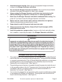
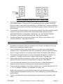
1
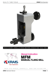
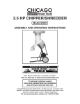
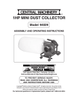
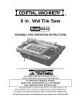
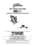
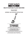
NITROGEN GENERATOR
AND INFLATER
95105
ASSEMBLY AND OPERATING INSTRUCTIONS
Due to continuing improvements,
actual product may differ slightly
from the product described herein.
®
3491 MISSION OAKS BLVD., CAMARILLO, CA 93011
VISIT OUR WEB SITE AT HTTP://WWW.HARBORFREIGHT.COM
Copyright © 2006 by Harbor Freight Tools®. All rights reserved. No portion of
this manual or any artwork contained herein may be reproduced in any shape
or form without the express written consent of Harbor Freight Tools.
For technical questions and replacement parts, please call 1-800-444-3353
SPECIFICATIONS
Item
Function
Power Requirement
Nitrogen Output
Nitrogen Input
Air Inlet Pressure
Power Switch
Power Indicator
Tire Inflator
Overall Dimensions
Weight
Description
Inflates tires with nitrogen instead of air
110 VAC, 60 Hz, 234 watts
85 PSI from 3 internal tanks (50 liter total capacity)
Rear connector for external tank
130 to 140 PSI
Toggle: On/Off
LED Lights when Power Switch is on.
Pressure gauge with tire chuck hose
39-5/8 (H) x 13-3/4 (D) x 25-5/8 (W) inches;
4 inch floor clearance
174 lb.
SAVE THIS MANUAL
You will need the manual for the safety warnings and precautions, assembly instructions,
operating and maintenance procedures, parts list and diagram. Keep your invoice with this
manual. Write the invoice number on the inside of the front cover. Keep the manual and
invoice in a safe and dry place for future reference.
GENERAL SAFETY RULES
WARNING!
READ AND UNDERSTAND ALL INSTRUCTIONS. Failure to follow all instructions
listed below may result in electric shock, fire, and/or serious injury.
SAVE THESE INSTRUCTION
Work Area
1.
Keep your work area clean and well lit. Cluttered benches and dark areas invite
accidents.
2.
Do not operate power tools in explosive atmospheres, such as in the presence
of flammable liquids, gases, or dust. Power tools create sparks which may ignite
the dust or fumes.
3.
Keep bystanders, children, and visitors away while operating a power tool.
Distractions can cause you to lose control. Protect others in the work area from
debris such as chips and sparks. Provide barriers or shields as needed.
SKU 95105
For technical questions, please call 1-800-444-3353
Page 2
Electrical Safety
4.
Avoid body contact with grounded surfaces such as pipes, radiators, ranges,
and refrigerators. There is an increased risk of electric shock if your body is
grounded.
5.
Do not expose power tools to rain or wet conditions. Water entering a power tool
will increase the risk of electric shock.
6.
Grounded tools must be plugged into an outlet properly installed and grounded
in accordance with all codes and ordinances. Never remove the grounding
prong or modify the plug in any way. Do not use any adapter plugs. Check with
a qualified electrician if you are in doubt as to whether the outlet is properly
grounded. If the tools should electrically malfunction or break down, grounding
provides a low resistance path to carry electricity away from the user.
7.
Double insulated tools are equipped with a polarized plug (one blade is wider
than the other). This plug will fit in a polarized outlet only one way. If the plug
does not fit fully in the outlet, reverse the plug. If it still does not fit, contact a
qualified electrician to install a polarized outlet. Do not change the plug in any
way. Double insulation
eliminates the need for the three wire grounded power
cord and grounded power supply system.
8.
Do not abuse the Power Cord. Never use the Power Cord to the Plug from an
outlet. Keep the Power Cord away from heat, oil, sharp edges, or moving parts.
Replace damaged Power Cords immediately. Damaged Power Cords increase the
risk of electric shock.
9.
When operating a power tool outside, use an outdoor extension cord marked
“W-A” or “W”. These extension cords are rated for outdoor use, and reduce the risk
of electric shock.
Personal Safety
10.
Stay alert. Watch what you are doing, and use common sense when operating a
power tool. Do not use a power tool while tired or under the influence of drugs,
alcohol, or medication. A moment of inattention while operating power tools may
result in serious personal injury.
11.
Dress properly. Do not wear loose clothing or jewelry. Contain long hair. Keep
your hair, clothing, and gloves away from moving parts. Loose clothes, jewelry, or
long hair can be caught in moving parts.
12.
Avoid accidental starting. Be sure the Power Switch is off before plugging in.
Plugging in power tools with the Power Switch on, invites accidents.
13.
Do not overreach. Keep proper footing and balance at all times. Proper footing
and balance enables better control of the power tool in unexpected situations.
14.
Use safety equipment. Always wear eye protection. Dust mask, nonskid safety
shoes, hard hat, or hearing protection must be used for appropriate conditions.
SKU 95105
For technical questions, please call 1-800-444-3353
Page 3
Tool Use and Care
15.
Do not force the tool. Use the correct tool for your application. The correct tool
will do the job better and safer at the rate for which it is designed.
16.
Do not use the power tool if the Power Switch does not turn it on or off. Any tool
that cannot be controlled with the Power Switch is dangerous and must be replaced.
17.
Disconnect the Power Cord Plug from the power source before making any
adjustments, changing accessories, or storing the tool. Such preventive safety
measures reduce the risk of starting the tool accidentally.
18.
Store idle tools out of reach of children and other untrained persons. Tools are
dangerous in the hands of untrained users.
19.
Maintain tools with care. Keep cutting tools sharp and clean. Properly
maintained tools with a sharp cutting edge are less likely to bind and are easier to
control. Do not use a damaged tool. Tag damaged tools “Do not use” until repaired.
20.
Check for misalignment or binding of moving parts, breakage of parts, and any
other condition that may affect the tool’s operation. If damaged, have the tool
serviced before using. Many accidents are caused by poorly maintained tools.
21.
Use only accessories that are recommended by the manufacturer for your
model. Accessories that may be suitable for one tool may become hazardous when
used on another tool.
Service
22.
Tool service must be performed only by qualified repair personnel. Service or
maintenance performed by unqualified personnel could result in a risk of injury.
23.
When servicing a tool, use only identical replacement parts. Follow
instructions in the “Inspection, Maintenance, And Cleaning” section of this
manual. Use of unauthorized parts or failure to follow maintenance instructions may
create a risk of electric shock or injury.
SPECIFIC SAFETY RULES FOR THIS PRODUCT
1.
Maintain labels and nameplates on the Nitrogen Generator and Inflater. These
carry important information. If unreadable or missing, contact Harbor Freight Tools for
a replacement.
2.
Always wear ANSI-approved safety impact eye goggles and heavy work gloves
when using the Nitrogen Generator and Inflater. Using personal safety devices
reduce the risk for injury. Safety impact eye goggles and heavy work gloves are
available from Harbor Freight Tools.
3.
Maintain a safe working environment. Keep the work area well lit. Make sure there
is adequate surrounding workspace. Always keep the work area free of obstructions,
grease, oil, trash, and other debris. Do not use a power tool in areas near flammable
chemicals, dusts, and vapors. Do not use this product in a damp or wet location.
SKU 95105
For technical questions, please call 1-800-444-3353
Page 4
4.
Avoid unintentional starting. Make sure you are prepared to begin work before
turning on the Nitrogen Generator and Inflater.
5.
Do not force the Nitrogen Generator and Inflater. This tool will do the work better
and safer at the speed and capacity for which it was designed.
6.
Always unplug the Nitrogen Generator and Inflater from its electrical outlet
before performing any inspection, maintenance, or cleaning procedures.
7.
Never leave the Nitrogen Generator and Inflater unattended while running. Turn
power off if you have to leave the Nitrogen Generator and Inflater.
8.
Before each use, check all nuts, bolts, and hose connections for tightness.
Vibration during mixing may cause these to loosen.
9.
Keep extension cord off the ground and away from water.
10.
Always connect the Line Cord to a Ground Fault Circuit Interrupter (GFCI)
protected electrical outlet.
11.
Install this product on a proper surface. Locate on a flat, level, and solid surface
that is capable of supporting the weight of the Nitrogen Generator and Inflater.
GROUNDING
WARNING!
Improperly connecting the grounding wire can result in the risk of electric shock.
Check with a qualified electrician if you are in doubt as to whether the outlet is
properly grounded. Do not modify the power cord plug provided with the tool or
product. Never remove the grounding prong from the plug. Do not use the tool if
the power cord or plug is damaged. If damaged, have it repaired by a service
facility before use. If the plug will not fit the outlet, have a proper outlet installed
by a qualified electrician.
Grounded Tools with Three Prong Plugs
1.
This product comes with a three prong plug. Tools marked with “Grounding Required”
have a three wire cord and three prong grounding plug. The plug must be connected
to a properly grounded outlet. If the tool should electrically malfunction or break down,
grounding provides
(1) a low resistance path to carry electricity away from the user,
reducing the risk of electric shock. (See Figure A.)
2.
The grounding prong in the plug is connected through the green wire inside the cord
to the grounding system in the tool. The green wire in the cord must be the only wire
connected to the tool’s grounding system and must never be attached to an
electrically “live” terminal. (See Figure A.)
3.
Your tool must be plugged into an appropriate outlet, properly installed and grounded
in accordance with all codes and ordinances. The plug and outlet should look like
those in the following illustration. (See Figure A.)
SKU 95105
For technical questions, please call 1-800-444-3353
Page 5
Figure B
Figure A
Double Insulated Tools with Two Prong Plugs
4.
A polarized plug (one blade is wider than the other) is used as a feature to reduce the
risk of electric shock. This plug will fit in a polarized outlet only one way. If the plug
does not fit fully in the outlet, reverse the plug. If it still does not fit, contact a qualified
electrician. Never use with an extension cord unless plug can be fully inserted. Do not
alter the plug.”
5.
Tools marked “Double Insulated” do not require grounding. They have a special double
insulation system which satisfies OSHA requirements and complies with the
applicable standards of Underwriters Laboratories, Inc., the Canadian Standard
Association, and the National Electrical Code. (See Figure B above.)
6.
Double insulated tools may be used in either of the 120 volt outlets shown in the
following illustration. (See Figure B above.)
EXTENSION CORDS
1.
Grounded tools require a three wire extension cord. Double Insulated tools can use
either a two or three wire extension cord.
2.
As the distance from the supply outlet increases, you must use a heavier gauge
extension cord. Using extension cords with inadequately sized wire causes a serious
drop in voltage, resulting in loss of power and possible tool damage. (See Table A.)
3.
The smaller the gauge number of the wire, the greater the capacity of the cord. For
example, a 14 gauge cord can carry a higher current than a 16 gauge cord.
4.
When using more than one extension cord to make up the total length, make sure
each cord contains at least the minimum wire size required. (See Table A.)
5.
If you are using one extension cord for more than one tool, add the nameplate
amperes and use the sum to determine the required minimum cord size.
6.
If you are using an extension cord outdoors, make sure it is marked with the suffix “WA” (“W” in Canada) to indicate it is acceptable for outdoor use.
7.
Make sure your extension cord is properly wired and in good electrical condition.
Always replace a damaged extension cord or have it repaired by a qualified electrician
before using it.
8.
Protect your extension cords from sharp objects, excessive heat, and damp or wet
areas.
SKU 95105
For technical questions, please call 1-800-444-3353
Page 6
Table A
RECOMMENDED MINIMUM WIRE GAUGE FOR EXTENSION CORDS*
(120 VOLT)
NAMEPLATE
AMPERES
EXTENSION CORD LENGTH
(At Full Load)
25
50
75
100
150
Feet
Feet
Feet
Feet
Feet
0 – 2.0
18
18
18
18
16
2.1 – 3.4
18
18
18
16
14
3.5 – 5.0
18
18
16
14
12
5.1 – 7.0
18
16
14
12
12
7.1 – 12.0
16
14
12
10
12.1 – 16.0
14
12
10
16.1 – 20.0
12
10
* Based on limiting the line voltage drop to five volts at 150% of the rated amperes.
SYMBOLOGY
Table B
UNPACKING
When unpacking, check to make sure that all the parts are included. Refer to the Assembly
section, and the Assembly Drawing and Parts List at the end of this manual. Also see
Figure C on the next page.
If any parts are missing or broken, please call Harbor Freight Tools at the number on the
cover of this manual as soon as possible.
SKU 95105
For technical questions, please call 1-800-444-3353
Page 7
Air Outlet
Main Unit
N2 Outlet
Tire Inflation Unit
Blue N2 Hose (505)
Orange Air Hose (506)
Figure C
ASSEMBLY INSTRUCTIONS
1.
Connect the orange Air Hose (506) to the Air Inlet (when facing fittings, viewed on left
side) of the Tire Inflation Unit, and to the Main Unit Air outlet. For these steps, refer to
Figures C and D.
Refer to connector labels on each unit. Hose connectors snap on.
2.
Connect the blue N2 Hose (505) to the Tire Inflation Unit N2 Inlet (right side when
facing fittings), and to the Main Unit N2 Outlet.
3.
Connect the air supply hose (not supplied) from the air compressor (not supplied) to
the Filter - Regulator (10) on the Main Unit. See Figure D, left-side.
4.
Optionally, if an additional, larger N2 supply tank is required, it can be connected to the
rear of Main Unit labeled N2 Outlet. The hose for this connection is not supplied.
Filter-Regulator (10)
Hose Connection from
Air Compressor
Main Unit (front)
Hose Connections
Main Unit (rear)
Extra N2 Tank
Connection
Figure D
SKU 95105
For technical questions, please call 1-800-444-3353
Page 8
OPERATING INSTRUCTIONS
Controls and Indicators
Air Pressure
Gauge
A - N2 Generation
Indicator
N2 Purity Analysis
Display
B - N2 Generation
Indicator
Power Indicator
N2 Pressure
Gauge
Power Switch
Figure E
Inflating Tires
This process extracts air from the tire and replaces it with Nitrogen. Follow these steps after
the Assembly Instructions have been completed.
1.
From the Tire Inflation Unit, connect the rubber hose (with tire valve clamp) to the tire
air valve. The tire can be off or on the vehicle during this process. (If tire is left on the
vehicle, jack it up to avoid possible sidewall damage to tire.)
2.
Turn on the air compressor and set its regulator for between 130 and 140 PSI.
3.
Turn the Power Switch to the On position.
- The Power Indicator will light.
- Check the Air Pressure Gauge for proper level.
4.
From the Tire Inflation Unit, turn the Converse Valve clockwise, and open (inline with
hose) the Air Inlet valve.
This step extracts the air from the tire. Inspect the tire for any leakage. Note: If this
“flats” the tire, it should be raised so rim does not damage tire.
5.
When air has been extracted, close (90° to air hose) the Air Inlet valve.
Tire Pressure Gauge
Converse Valve
Tire Inflation
Unit
N2 Inlet Valve
Air Inlet Valve
Figure F
SKU 95105
For technical questions, please call 1-800-444-3353
Page 9
6.
From the Tire Inflation Unit, turn the Converse Valve counterclockwise, and open
(inline with hose) the N2 Inlet valve.
•
This step inflates the tire with Nitrogen.
• Check the Tire Pressure Gauge on the Tire Inflation Unit, and inflate to the tire
manufacturer’s recommended tire pressure.
• The A or B N2 Generation Indicator will light. The N2 Pressure Gauge should read
85 PSI.
• Check the N 2 Purity Analysis Display on the Main Unit. Purity should read between
95% to 99%. If it does not, N2 supply tank may be low.
7.
When the tire is inflated to the proper pressure, close (90° to hose) the N 2 Inlet valve,
and remove the rubber hose with tire valve clamp from the tire valve.
8.
Turn the Nitrogen Generator and Inflater Power Switch to the Off position.
9.
Turn the air compressor off and disconnect the air hose from the Nitrogen Generator
and Inflater.
TROUBLESHOOTING
Problem
Probable Cause
Possible Solution
Tire does not inflate or
deflate.
1. Air or N2 hoses not correctly
connected.
1. Review Assembly steps on
page 8.
-
Power Switch on
-
Power Indicator on
2. Air Compressor not supplying
air pressure, or not
connected.
2. Check air compressor is on
and hoses are correctly
connected.
3. Not following proper
operation procedure.
3. Review operating procedure
on page 9.
4. Tire valve hose connector not
inserted properly.
4. Reconnect tire valve hose
connector.
1. Adjustment of the N2 Purity
1. Adjust the N2 Purity Flow
N2 Purity Analysis Display
reads less than 95%
SKU 95105
Flow Rate screw is required
Rate screw.
For technical questions, please call 1-800-444-3353
Page 10
INSPECTION, MAINTENANCE, AND CLEANING
WARNING! Make sure the Power Switch of the NITROGEN GENERATOR AND INFLATER is in its “OFF” position and that the tool is unplugged from its electrical outlet
before performing any inspection, maintenance, or cleaning procedures.
1.
Before each use, inspect the general condition of the Nitrogen Generator and
Inflater. Check for loose screws, misalignment or binding of moving parts, cracked or
broken parts, damaged electrical wiring, and any other condition that may affect its
safe operation. If abnormal noise or vibration occurs, have the problem corrected
before further use. Do not use damaged equipment.
2.
Periodically recheck all hoses, valves, nuts, bolts, and screws for tightness.
3.
After each daily use of this unit, drain the moisture and impurities from the FilterRegulator (10). This extends the life of the filter. To do this, remove the air supply hose
from the Nitrogen Generator and Inflater, then press the Drain Button on the FilterRegulator (10).
4.
Before long-term unit storage, release pressure from the Nitrogen Generator and
Inflater.
5.
Replace the filter in Filter-Regulator (10) after one year of usage.
6.
Store in a clean and dry location.
7.
All maintenance and repairs must be completed by a qualified technician.
PLEASE READ THE FOLLOWING CAREFULLY
THE MANUFACTURER AND/OR DISTRIBUTOR HAS PROVIDED THE PARTS DIAGRAM
IN THIS MANUAL AS A REFERENCE TOOL ONLY. NEITHER THE MANUFACTURER NOR
DISTRIBUTOR MAKES ANY REPRESENTATION OR WARRANTY OF ANY KIND TO THE
BUYER THAT HE OR SHE IS QUALIFIED TO MAKE ANY REPAIRS TO THE PRODUCT OR
THAT HE OR SHE IS QUALIFIED TO REPLACE ANY PARTS OF THE PRODUCT. IN FACT,
THE MANUFACTURER AND/OR DISTRIBUTOR EXPRESSLY STATES THAT ALL REPAIRS
AND PARTS REPLACEMENTS SHOULD BE UNDERTAKEN BY CERTIFIED AND LICENSED
TECHNICIANS AND NOT BY THE BUYER. THE BUYER ASSUMES ALL RISK AND
LIABILITY ARISING OUT OF HIS OR HER REPAIRS TO THE ORIGINAL PRODUCT OR
REPLACEMENT PARTS THERETO, OR ARISING OUT OF HIS OR HER INSTALLATION
OF REPLACEMENT PARTS THERETO.
SKU 95105
For technical questions, please call 1-800-444-3353
Page 11
PARTS LIST
NOTE: Some parts are listed and shown for illustration purposes only and are not available individually as replacement parts.
Part #
1
2
3
4
5
6
7
8
9
10
11
12
13
14
A1
101
102
103
104
105
106
107
108
109
110
111
112
113
114
115
116
117
118
A2
201
202
203
204
205
206
SKU 95105
Description
Tool Plate
Screw, M6x10
Main Body
Screw, M6x15
Pressure Gauge
Power Indicator
N2 Indicator
N2 Purity Analysis Board
Power Switch
Filter with Pressure Regulator
Elbow Connector, ¼” x 8
3-way Connector
Needle Valve
Drain Hose, Blue
Qty.
1
10
1
8
2
1
2
1
1
1
1
3
1
2
Time Relay
Pressure Switch (10 kgs)
Pressure Switch (6 kgs)
Electromagnetic Valve
Electromagnetic Valve (2-5)
Quick Connector, ¼”
Connector, ¼” x 8
Electric Hose Sleeve
Elbow Connector, ¼” x 8
Silencer
Screw, M4 x 30
Connector, 10 x 1.25-8
Screw, M4 x 15
Screw, M4 x 20
Screw, M4 x 10
Screw, M4 x 10, Flathead
Transformer, 2W
Transformer, 50W
1
1
1
1
1
3
3
1
3
2
2
2
4
2
8
2
1
1
N2 Tank
3-way Connector, ¼”
Connector, ¼” x 3/8”
Screw, M8 x 20
Safety Valve
Elbow Connector, ¼” x 8
1
1
1
5
1
2
Part #
A3
Description
301/302
Filtration Tank
303
3-way Connector, ¼”
304
One-way Valve
305
Elbow Connector, ¼”
306
Connector, ½” x 2
307
Connector, ½”
308
Connector, ¼” x 8
309
Elbow Connector, ¼” x 8
A4
401
Air Inlet Connector, ¼”
402
Ball Valve, ¼”
403
Pressure Gauge
404
Connector, ¼”
405
Gauge Stand
406
Connector, ¼” x 8
407
Elbow Connector, ¼” x 8
408
Converse Valve
409
Handle
410
Screw, M6 x 16
411
Body, Tire Inflation Unit
412
Support Screw
413
Vacuum Generator, Complete
Other Parts
501
Power Cord
502
Hose Sleeve
503
Washer, M6
504
Washer, M8
505
N2 Hose, Blue
506
Air Hose, Orange
507
Inflation Rubber Hose
508
Nut, M8
509
Nut, M4
For technical questions, please call 1-800-444-3353
Qty.
2
1
2
2
2
2
1
1
3
2
1
2
3
3
2
1
1
12
1
4
1
1
2
26
5
10M
10M
1M
5
6
Page 12
MAIN UNIT MAJOR ASSEMBLY DRAWING
SKU 95105
For technical questions, please call 1-800-444-3353
Page 13
MAIN UNIT SUBASSEMBLY DRAWINGS
SKU 95105
For technical questions, please call 1-800-444-3353
Page 14
TIRE INFLATER UNIT ASSEMBLY DRAWING
SKU 95105
For technical questions, please call 1-800-444-3353
Page 15
WARRANTY
LIMITED 90 DAY/1 YEAR WARRANTY
Harbor Freight Tools Co. makes every effort to assure that its products meet high quality and durability standards,
and warrants to the original purchaser for a period of ninety days from date of purchase that the motor, the belts
(if so equipped), and the blades (if so equipped) are free of defects in materials and workmanship. Harbor Freight
Tools also warrants to the original purchaser, for a period of one year from date of purchase, that all other parts
and components of the product are free from defects in materials and workmanship. This warranty does not apply
to damage due directly or indirectly to misuse, abuse, negligence or accidents; repairs or alterations outside our
facilities; or to lack of maintenance. We shall in no event be liable for death, injuries to persons or property, or for
incidental, contingent, special or consequential damages arising from the use of our product. Some states do
not allow the exclusion or limitation of incidental or consequential damages, so the above limitation of exclusion
may not apply to you. THIS WARRANTY IS EXPRESSLY IN LIEU OF ALL OTHER WARRANTIES, EXPRESS
OR IMPLIED, INCLUDING THE WARRANTIES OF MERCHANTABILITY AND FITNESS.
To take advantage of this warranty, the product or part must be returned to us with transportation charges prepaid.
Proof of purchase date and an explanation of the complaint must accompany the merchandise. If our inspection
verifies the defect, we will either repair or replace the product at our election or we may elect to refund the purchase
price if we cannot readily and quickly provide you with a replacement. We will return repaired products at our
expense, but if we determine there is no defect, or that the defect resulted from causes not within the scope of
our warranty, then you must bear the cost of returning the product.
This warranty gives you specific legal rights and you may also have other rights which vary from state to state.
3491 Mission Oaks Blvd. • PO Box 6009 • Camarillo, CA 93011 • (800) 444-3353
SKU 95105
For technical questions, please call 1-800-444-3353
Page 16