1
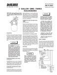
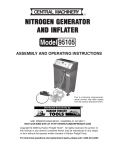
Service Bulletin
SBBI-21-068-G
Replaces SBBI-21-068-F
83G (GALVANIZED) AND 83S (STAINLESS STEEL) TANKS
Small Tank – Up to 2.8 Gallons
IMPORTANT: Read and follow all instructions and SAFETY PRECAUTIONS before
using this equipment. Retain for future reference.
STANDARD FLUID REGULATED TANKS
(Single Regulation)
Standard type tanks for use on jobs where
precision control of both fluid and atomization air pressures is not required. Also used
where atomization air can be taken from
filter/regulator air lines. Provides standard
fluid pressure control only. Equipped with
pressure regulator, pressure gauge, air bleed
down valve, safety valve, and inlet and
outlet air valves. (For conversion to double
regulation, use kit QMS-436.)
STANDARD AIR AND FLUID REGULATED
TANKS
(Dual Regulation)
DESCRIPTION
Binks pressure feed tanks are intended for
use as a pressure container to supply material at a constant preset pressure up to a
maximum of 110 psi. The tanks are built to
ASME specifications.
Precision controlled tanks for use with materials that are best applied at low, closely
controlled, fluid and atomization air pressures. Used with portable air compressors or
with air lines when no other means of air
pressure regulation is available. Equipped
with two regulators (one for fluid pressure,
the other for atomization air pressure), two
pressure gauges, air bleed down valve, safety
valve, and inlet and outlet valves.
Static electricity is created by the
flow of fluid through the pressure
tank and hose. If all parts are not
properly grounded, sparking may
occur. Sparks can ignite vapors
from solvents and the fluid being
sprayed.
If static sparking, or slight shock,
is experienced while using this
equipment, stop spraying
immediately.
Ground the pressure tank by
connecting one end of a 12 gauge
minimum ground wire to the
pressure tank and the other end
to a true earth ground. Local codes
may have additional grounding
requirements.
See illustration, page 5, for
grounding and grounding
hardware required.
AGITATION
Pressure tanks can be equipped with different types of fluid agitation, or no agitation.
Pressure Relief Procedure
(Galvanized Tanks)
Halogenated hydarbon solvents for example: 1, 1, 1, trichloroethane and methylene
chloride - can chemically react
with aluminum parts and components and cause an explosion hazard. These solvents will also corrode the galvanized tank coating.
Read the label or data sheet for
the material. Do not use materials containing these solvents with
galvanized pressure tanks. Stainless steel tank models may be
used with halogenated solvents.
Refer to specifications chart to
ensure that fluids and solvents
being used are chemically
compatible with the tank wetted
parts. Before placing fluids or
solvents in tank always read
accompanying manufacturer’s
literature.
Air pressure loads that are higher
than design loads, or changes to
the pressure feed tank, can cause
the tank to rupture or explode.
• A safety valve protects the
tank from overpressurization.
During each use, pull ring on the
safety valve to make sure it
operates freely and relieves air
pressure. If the valve is stuck,
does not operate freely, or does
not relieve air pressure, it must
be replaced with a safety valve
having the same rating. Do not
eliminate, make adjustments to,
or substitutions to this valve.
• Changes to the air tank will
weaken it. Never drill into, weld,
or change the tank in any way.
• Maximum working pressure of
this tank is 110 psi.
High pressure can cause a serious
injury. Pressure is maintained in a
pressure tank after the system
has been shut down. Before
attempting removal of fill plug or
cover, pressure must be relieved
using the following steps:
1. Turn off the main air supply to
the tank.
2. Close air inlet valve located on
tank air manifold.
3. Bleed off air in the tank by
turning the air relief valve thumb
screw counterclockwise. Wait
until all the air has escaped
through the
valve before
removing the pressure tank cover
or fill plug.
4. Leave the air relief valve open
until you have reinstalled the cover
or fill plug.
(Cont'd on Pg. 4)
PAGE 2
SBBI-21-068-G
SAFETY PRECAUTIONS
This manual contains important information that all users should know and understand before using the equipment. This information
relates to USER SAFETY and PREVENTING EQUIPMENT PROBLEMS. To help you recognize this information, we use the following terms
to draw your attention to certain equipment labels and portions of this Service Bulletin. Please pay special attention to any label or
information that is highlighted by one of these terms.
Note
Important information to alert you to a
situation that might cause serious injury
if instructions are not followed.
Important information that tells how to
prevent damage to equipment, or how to
avoid a situation that might cause minor
injury.
Information that you should pay
special attention to.
The following hazards may occur during the normal use of this equipment. Please read the following chart.
HAZARD
CAUSE
SAFEGUARDS
Fire
Solvents and coatings can be highly
flammable or combustible, especially
when sprayed.
1. Adequate exhaust must be provided to keep the
air free of accumulations of flammable vapors.
2. Smoking must never be allowed in the spray
area.
3. Fire extinguishing equipment must be present
in the spray area.
Fire Pressure Tank
Vapors from flammable liquids can
catch fire or explode.
1. Keep tank at least 10 feet away from sources of
ignition. Ignition sources include hot objects,
mechanical sparks, and arcing (non-explosion
proof) electrical equipment.
Inhaling Toxic Substances
Certain materials may be harmful if
inhaled, or if there is contact with the
skin.
1. Follow the requirements of the Material Safety
Data Sheet supplied by your coating material
manufacturer.
2. Adequate exhaust must be provided to keep
the air free of accumulations of toxic materials.
3. Use a mask or respirator whenever there is a
chance of inhaling sprayed materials. The mask
must be compatible with the material being
sprayed and its concentration. Equipment must
be as prescribed by an industrial hygienist
or safety expert, and be NIOSH approved.
Explosion Hazard Pressure Tank Rupture
Making changes to pressure tank will
weaken it.
1. Never drill into, weld, or modify tank in any way.
General Safety
Improper operation or maintenance
may create a hazard.
2. Do not adjust, remove, or tamper with the safety
valve. If replacement is necessary, use the same
type and rating of valve.
Operators should be given adequate training in the
safe use and maintenance of the equipment (in accordance with the requirements of NFPA-33, Chapter
15 in U.S.). Users must comply with all local and
national codes of practice and insurance company
requirements governing ventilation, fire precautions,
operation, maintenance and housekeeping (in the
U.S., these are OSHA Sections 1910.94 and 1910.107,
and NFPA-33).
SBBI-21-068-G
2.8 GAL
83G
DIMENSIONS
GALVANIZED MODELS
Air
Fluid
Regulation
Agitation*
83G-210
83G-220
83G-211 (D)
83G-221 (D)
83G-213 (I)
Single Reg
Double Reg
Single Reg
Double Reg
Single Reg
PAGE 3
Inside
Inside Height Overall Overall
Diameter
at Center
Height* Width
(Inches)
(Inches)
(Inches) (Inches)
No Agitation
No Agitation
Std. Agitation
Std. Agitation
Opt. Agitation
9-1/2
9-1/2
13-13/16
Weight*
(Pounds)
13-3/8
30
(Galvanized)
25
(Stainless Steel)
*Basic tank, not including regulators or agitation.
STAINLESS MODELS
2.8 GAL
83S
Air
Regulation
Fluid
Agitation*
83S-210
83S-220
83S-211 (D)
83S-221 (D)
83S-213 (I)
83S-200 (A)
83S-223
83S-226
Single Reg
Double Reg
Single Reg
Double Reg
Single Reg
None
Double Reg
Double Reg
No Agitation
* (D) = Direct Drive Agitator: Uses direct mount air
No Agitation
motor and air adjusting valve.
Std. Agitation
Std. Agitation
* (I) = Indirect Drive Agitator: Air motor coupled to
gearbox for higher torque at lower speeds.
Opt. Agitation
None
* (A) = No air regulation/no agitation. Uses QMSOpt. Agitation
4003 No Regulation Kit for air connection.
Recip. Agitation
SPECIFICATIONS
(GALVANIZED TANKS)
(STAINLESS STEEL TANKS)
Maximum Working Pressure
110 psi
110 psi
Tank Shell
SA-414 H.R. Steel Zinc
Plate 12 gauge (0.105 In.) thick
304 Stainless Steel
14 gauge (.075 in.) thick
Tank Lid
SA-414 H.R. Steel Zinc
Plate 3/16 in. thick
304 Stainless Steel
3/16 in. thick
Agitator Shaft
CRS Zinc Plate
303 Stainless Steel
Fluid Tube
Galvanized Zinc Plate
3/8 in. pipe
316 Stainless Steel
3/8 in. pipe
Fluid Valve, Outlet
Brass 3/8-18 NPSM outlet
316 Stainless Steel 3/8-18 NPS(M) outlet
Air Manifold
CRS Zinc Plated
CRS Zinc Plated
Shaft Seal
Engineered Teflon,
Stainless Steel
Engineered Teflon,
Stainless Steel
Agitator Paddles
Nylon, Glass Filled
Nylon, Glass Filled
Fluid Outlet
Galvanized Steel Zinc Plate
316 Stainless Steel
Bottom Outlet (Optional Kit)
304 Stainless Steel
3/4 in. NPS(M) outlet
304 Stainless Steel
3/4 in. NPS(M) outlet
TO ASSEMBLE REGULATORS AND HOSE TO TANK
Assemble single regulator to
manifold using an 11/16 wrench.
Assemble double regulator to
manifold using an 11/16 wrench.
Assemble hose to either manifold using a 5/8 wrench.
PAGE 4
SBBI-21-068-G
Mix and prepare material to be used according to manufacturer’s instructions. Strain
material through a fine mesh screen to
remove lumps, skin, and foreign matter that
might enter and clog fluid passages and/or
spray equipment.
1.
2.
Follow pressure relief procedures
above.
To add material to 2 gallon tanks, remove lid and pour directly into the
tank or container.
3.
Turn T-handle adjusting screw on tank
fluid regulator counterclockwise until
no spring pressure is felt.
OPERATION
4.
Loosen thumb screws (5), tip clamps
(6) back, and tip lid (12) to one side of
tank. Do not remove lid from tank.
5.
Loosen spray gun air cap retaining
ring about three turns.
6.
Turn on air supply.
7.
Cup cloth over air cap on the gun and
pull trigger. This will force material
back through the hose into the tank.
8.
Empty and clean tank and parts that
come into contact with material. Use a
solvent compatible with material
being used.
9.
Pour solvent into tank.
1.
Turn on air supply to tank.
3.
Open air inlet valve to tank.
4.
Open fluid outlet valve.
5.
Turn handle on tank pressure regulator clockwise to pressurize tank. Clockwise increases material pressure; counterclockwise will decrease material
pressure.
If desired, a U.S. or metric 1 gallon
pail of fluid can be placed directly
into the tank.
4.
5.
6.
Turn on atomization air to spray gun
at source of supply.
7.
Test spray. For further instructions, see
spray gun service bulletin SB-2-001.
8.
If an air motor drive is used, start the
agitator by slowly opening the needle
valve. Air motor speed should be regulated according to the nature of the
material being agitated.
Replace the lid assembly and tighten
thumb screws (5) securely.
The air supply to the tank should include
a filter/water separator to filter dirt from
the air and remove water and oil. Connect the air supply line to the tank inlet
valve.
The pressure tank has a 1 inch NPT drain
port in the bottom of the tank. Bottom
outlet kits may be connected into the drain
1 0 . Replace lid and tighten thumb screws
and clamps.
11. Spray until clean solvent appears.
Connect the material hose to fluid
outlet ball valve (13).
USING BOTTOM OUTLET PORT
Close air inlet valve to tank. Turn
handle on regulator counterclockwise
until spring tension is relieved.
2.
Note
3.
page 1.
port. Use bottom outlet feature when top
outlet is not desirable. Direct bottom outlet
piping to either of two holes located in tank
skirt. A dolly to raise the tank off the floor is
not required.
PREVENTIVE MAINTENANCE
To clean equipment, proceed as follows:
1.
Turn off the air supply.
2.
Follow pressure relief procedure on
1 2 . Repeat steps 4 through 8.
LUBRICATION
Refer to the service manual provided with
the air motor for lubrication information.
The bearings in the agitator bearing assembly are impregnated with a special non-
SERVICE CHECKS
CONDITION
CAUSE
CORRECTION
A. Air escaping from port on
regulator cap.
1 . Broken or damaged diaphragm.
1 . Replace diaphragm.
B. Pressure creepage registered
on gauge.
1 . Dirty or worn valve seat in
regulator.
1 . Clean or replace valve seat.
C. Material tends to settle out
rapidly.
1 . Not enough agitation of material.
1 . Increase agitation.
D. Air leakage at agitator seal.
1 . Defective seal assembly.
1 . Replace.
E. Paint getting into bearing
assembly of agitator.
1. Paint level in tank too high.
2 . Defective agitator shaft seal.
1. Do not fill tank above agitator
bearing assembly.
2 . Replace.
F. Fluid or air leak at lid gasket.
1 . Thumb screw not tight.
2 . Defective lid gasket.
1 . Tighten.
2 . Replace.
G. Air mixing with paint.
1 . Fluid tube not sealed to lid.
2 . Excessive agitation.
1 . Tighten fluid tube into lid.
2 . Reduce speed of agitator.
NOTE: Occasionally check pressure gauge. The needle should return to zero with no pressure on the gauge.
SBBI-21-068-G
2 Gallon Steel Tank Exploded View
Refer to Accessories
for optional agitators
and drives.
Note 1
Use a Teflon based thread sealant on
all air/fluid connections.
Refer to Accessories
for regulator options.
17
18
16
Note 2
Open side of Shaft Seal (23A) faces
downward.
Retainer (23B) required only if tank is
used for vacuum operaton.
1
34
19
Used only with
bottom outlet. 15
33
#20
21
21
Grounding Diagram
Purchase hardware locally
32
22
14
13
5/16–18 x 3/4 Long
Hex Head Bolt
(1 Required)
12
Sufficient Length
12 Gauge Wire
(Not Shown)
11
Note
Standard with
direct drive
agitation
5/16–18 Hex Head Nut
(2 Required)
31
Used with no
agitation.
2X
Orient gasket (11) with ridge on
gasket facing towards the lid.
23A 23 (See Parts List
23B Note 2)
Replacement
#25
9
26 24
27
10
Standard
with hand/
gear driven
agitation.
30
29
16
28
2
4
3
6
5
8
PAGE 5
Ref
No.
Part No. (2 gal.
Galvanized)
Replacement
Part No. (2 gal.
Stainless Steel)
1
2
TIA-5110
PT-78-K10, K60
Same
Same
+3
•+4
+5
+6
7
8
9
10
11
12
13
•14
•15
16
--------QMG-46
----QMG-502
----PT-31
QMG-35
QMS-80-1
QMG-400
VA-540
-----(brass)
----QMG-416
--------Same
----QMS-502
----QMS-9-1
QMS-53-1
Same
QMS-416
VA-527 (316 s.s.)
SSP-1939(s.s.)
----QMS-430
17
18
QN-97
QMG-429
Same
QMS-428
19
KK-4990
KK-4991
#20
•21
22
23
--------SSG-8184-K2
KK-5041
--------Same
Same
23A
23B
24
--------KK-4990
--------KK-4991
#25
•26
27
28
--------QMG-56
QMS-448
--------QMS-73
Same
•29
30
31
32
•33
34
--------QMG-17
QMG-21
----SS-2707
--------QMS-2
Same
----Same
7
For bottom outlet
conversion remove
and discard plug.
# When replacing either Ref. Nos. 20 or 25, you must order
KK-4990 (Galvanized) or KK-4991 (Stainless Steel) which
includes both parts.
+ KK-5013 Clamp, Pin & Screw Kit includes 1 each of
Items 3, 4, 5 & 6.
• Purchase locally.
5/16 Lock Washer
(1 Required)
Tank Skirt (Ref)
Description
Safety Valve Assembly, 110 psi
Disposable Tank Liner
(10 or 60 each)
Clevis Pin
Cotter Pin (1/8 dia x 1 in. lg.)
Thumb Screw
Clamp
Tank
Plug
Fluid Tube (direct drive agitator)
Fluid Tube
Lid Gasket (Santoprene)
Tank Lid
Ball Valve
90° St. Elbow (3/8-18 NPT(F)
Plug (3/8-18 NPT s.s.)
Agitator Assembly Direct Drive
(includes items 17 through 30)
Carrying Handle
Air Motor (Refer to SBBI-19-087
for service parts)
Adapter Kit (Includes items
20, 21, 25, and 26)
Adapter
Setscrew (1/4-20 x 1/4)
O-Ring Kit (Kit of 2)
Shaft Seal Kit (Fits 1/2" shaft
with direct drive air motor). See
pg. 8 for gear reduced models.
Shaft Seal
Retainer
Seal Retainer Kit (Includes
items 20, 21, 25, & 26)
Shaft Coupling
Set Screw (1/4-20 x 1/4, s.s.)
Agitator Shaft (1/2")
Agitator Propeller Kit (includes
items 29 & 30)
Set Screw (1/4-20 x 3/8, s.s.)
Agitator Propeller
Plug
Air Manifold
Street Elbow (1/4-18 NPT Brass)
Air Relief Valve
Ind.
Parts
Req.
1
1
4
4
4
4
1
1
1
1
1
1
1
1
1
1
1
1
1
1
4
1
1
1
1
1
1
2
1
1
1
1
1
1
1
1
PAGE 6
SBBI-21-068-G
ACCESSORIES
QMS-435 BOTTOM OUTLET CONVERSION KIT
QMS-4007 DUAL REGULATOR KIT (STANDARD)
Fittings that allow standard top outlet tank to feed from bottom
by removing plug in bottom port. Kit includes stainless steel
shutoff valve and all stainless steel parts.
5
4
Provides independent controls for fluid pressure in tank and
atomization air pressure. Kit includes two regulators with
gauges, inlet and outlet shutoff valves, and connection fittings.
Refer to SBBI-6-147 and 77-2781 for regulator service parts.
12
3
14
2
YY
1
11
13
15
Ref.
No.
Replacement
Part No.
1
-----
2
-----
3
-----
4
5
---------
10
Description
Adapter, 3/4" NPT
to 3/4-14 NPS(M)
Reducer Bushing, 3/4
to 1"
Ball Valve, 1 x 1 NPT(F)
150 PSI
Pipe Nipple
Street Elbow (1")
YY
1
XX
1
16
1
1
1
QMS-4006 SINGLE REGULATOR KIT (STANDARD)
9
Provides standard fluid pressure control only. For use
when atomization air is controlled by a separate filterregulator. Kit includes pressure regulator with gauge,
inlet and outlet shutoff
valves, and connection fittings. Refer to 77-2781 for
regulator service parts.
Replacement
Part No.
6
7
8
9
•XX
SSP-8217-ZN
VA-542
HAR-511
83-1290
----
•YY
----
Ref
No.
Replacement
Part No.
10
11
12
13
VA-542
HAR-507
83-1355
83-4233
7
YY
8
7
XX
Ref
No.
10
Qty.
14
15
16
•XX
83-1290
HAR-511
SSP-8217-ZN
----
•YY
----
6
Description
Qty
Swivel Adapter
Valve
Regulator
Gauge, 150 lbs.
Bushing, 3/8(m) x 1/4 (f)
(Supplied/Regulator)
Pipe Plug, 1/4 NPT (Supplied/Reg)
Use when fluid pressure in
tank is regulated by some
other separate controls. Kit
includes air shutoff valve,
gauge to read fluid pressure
in tank, and fittings.
27•
28
29
----83-1290
VA-542
• Purchase locally.
Valve
Regulator
Gauge, 100 lbs.
D.M. Nipple, 1/4 x 3/8
Universal Pipe Thread
Gauge, 150 lbs.
Regulator
Swivel Adapter
Bushing, 3/8(m) x 1/4 (f)
(Supplied/Regulator)
Pipe Plug, 1/4 NPT (Supplied/Reg)
2
1
1
1
1
1
1
2
2
1
2
1
1
2
QMS-436 CONVERSION TO DOUBLE REGULATOR
ASSEMBLY KIT
Adapts to tanks equipped with single regulator to provide
independent pressure control of atomization air and fluid pressures. Converts QMS-4006 single regulator to a QMS-4007 dual
regulator. Refer to SBBI-6-147 for regulator service parts.
1
24
25 23
QMS-4003 NO REGULATION KIT
Replacement
Part No.
-----
Qty
• Purchase locally.
• Purchase locally.
Ref
No.
26•
Description
28
27
29
26
Description
Swivel Coupling 1/4
NPS(M) x 1/4 NPT(F)
Street Tee (1/4")
Gauge 150 lb
Valve
YY
Qty
1
1
1
1
Ref
No.
Replacement
Part No.
Description
23
24
25
HAR-507
83-1355
83-4233
•YY
----
• Purchase locally.
Regulator
Gauge, 100 lbs.
D.M. Nipple, 1/4 x 3/8 Universal
Pipe Thread
Pipe Plug, 1/4 NPT (Supplied/Reg)
Qty
1
1
1
1
SBBI-21-068-G
QMS-4010 EXTRA SENSITIVE REGULATOR KIT
QS-5012 INDIRECT AGITATOR DRIVE
Use with electrostatic spray or other applications requiring
extremely sensitive nonfluctuating low pressure control. Kit includes one extra sensitive gauge, one extra sensitive regulator,
inlet and outlet shutoff valves, and connection fittings. Refer to
SBBI-6-131 for regulator service parts.
Standard duty 1/2 hp agitator
drive with 15:1 gear reduction.
Operates from 20 to 120 rpm.
Mounts on agitator shaft. Includes
throttling valve, fittings, and hose
for connection to air supply on
tank lid. Used with agitator
assembly shown on page 8.
For further information see
SBBI-19-087.
19
20
21
22
PAGE 7
31-381 RECIPROCATING AIR MOTOR DRIVE
17
Low air consumption motor mounts
easily on tanks equipped for material
agitation. Slow back and forth motion
ensures proper agitation. Operates at
10 to 30 cycles per minute. Used with
agitator assembly shown on page 8.
For more information see Part Sheet
77-2788.
20
18
18
19
Ref
No.
Replacement
Part No.
17
18
19
•20
SSP-8217-ZN
VA-542
SSP-2629-ZN
-----
21
HAR-501
22
83-1414
Description
Swivel Adapter
Valve
Tee Male Branch
Hex Reducer
Bushing (3/8 x 1/4
Galvanized)
Extra Sensitive
Regulator
Gauge, 30 lbs.
• Purchase locally.
VS-534 FLUID STRAINER
Primary fluid strainer that attaches between
fluid outlet valve and fluid hose to strain
material. Components made of stainless steel
with a nylon filter. Comes standard with 100mesh screen. For more information see
SBBI-7-072.
Qty
1
2
2
2
QMG-35 GALVANIZED BENT FLUID TUBE OR
QMS-53-1 STAINLESS STEEL BENT FLUID TUBE
QMS-79 SHORTER PROFILE AGITATOR PADDLE
If air bubbles (cavitation) form in material, a shorter paddle and
bent fluid tube takes the intake farther away from the agitator.
1
1
DISPOSABLE TANK LINERS
Molded polyethylene tank liners reduce
solvent waste and tank cleanup time. The
liner is made of tough, durable, leakproof
poly-ethylene and can be used with all
compatible materials.
PT-78-K10 Kit of 10 tank liners
PT-78-K60 Kit of 60 tank liners
PROSPECTORTM PRESSURE TANK STRAINERS
FOR 2 GALLON TANKS
HFRL-508, HFRL-509 CLEAN AIR™
CONTROL UNITS
These units are designed to remove dirt, pipe
scale and most liquid aerosol. Includes an
automatic drain which expels liquids which
accumulate in the filter bowl.
Prospector™ strainers are an economical way to remove foreign
material from paint, stain, lacquer and coatings.
Inner Diameter ................ 8.75" (222.25mm)
Outer Diameter ........... 10.625" (269.87mm)
Height/Depth ................... 2.625" (66.67mm)
Case Qty .................................................... 20
PTS-2Gal-K20-200 ..................... 200 micron
(approx. 65 wire mesh)
29-3100 SCRUBS® HAND CLEANER
TOWELS
Scrubs® are a pre-moistened hand cleaner
towel for painters. No water is needed.
PTS-2Gal-K20-400 ..................... 400 micron
(approx. 37 wire mesh)
PTS-2Gal-K20-600 ..................... 600 micron
(approx. 28 wire mesh)
PAGE 8
SBBI-21-068-G
AGITATOR ASSEMBLY FOR GEAR REDUCED DRIVE
All hardware needed to provide agitation of materials in tank except air motor
drive, which must be selected separately.
Replacement
Part No.
Galvanized
Replacement
Part No.
Stainless Steel
QMS-46
QMS-447
Same
Same
---------
---------
30
KK-5049
Same
31
32
33
QMG-409
SSG-8184-K2
KK-5042
QMS-407
Same
Same
34
35
36
37
--------QMG-15
QMS-449
--------QMS-5
Same
38
39
---------
---------
Ref
No.
26
27
28
•29
Description
Retaining Nut
Thrust Collar Kit
(includes items
28 and 29)
Thrust Collar
Set Screw
(5/16-18 x 3/8)
Thrust Washer Kit
(2 washers in kit)
Bearing Assembly
O-Ring
Shaft Seal Kit
(Fits 5/8" shaft with
gear reduced air
motors)
Shaft Seal
Retainer
Agitator Shaft
Agitator Propeller
Kit (includes
items 38 and 39)
Agitator Propeller
Hex Socket Head
Cap Screw
(5/16-18 x 1-1/4,
Stainless Steel)
26
Ind.
Parts
Req.
27
28
29
30
1
1
31
1
1
32
2
1
1
1
Open side of
Shaft Seal
(34) faces
downward.
1
1
1
1
34
35
33
Retainer (35) used for
vacuum operation.
Not required if tank is
used for pressure
only.
1
1
36
• Purchase locally.
39
37
38
WARRANTY
This product is covered by Binks' 1 Year Limited Warranty.
Binks Worldwide Sales and Service Listing: www.binks.com
ITW Industrial Finishing
Binks has authorized distributors throughout the world. For technical
assistance or the distributor nearest you, see listing below.
U.S./Canada Technical Service Office:
195 Internationale Blvd., Glendale Heights, IL 60139
Toll-Free Telephone: 1-888-992-4657 (U.S.A. and Canada only)
Toll-Free Fax: 1-888-246-5732
1/07 ©2007 Illinois Tool Works Inc. All rights reserved. Printed in U.S.A.