1
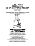
CHIPPER/SHREDDER
Model 95091
ASSEMBLY AND OPERATING INSTRUCTIONS
Do to continuing improvements, actual product may differ slighlty from the product described herein.
®
3491 Mission Oaks Blvd., Camarillo, CA 93011
Visit our Web site at: http://www.harborfreight.com
TO PREVENT SERIOUS INJURY,
READ AND UNDERSTAND ALL WARNINGS
AND INSTRUCTIONS BEFORE USE.
©
Copyright 2007 by Harbor Freight Tools®. All rights reserved. No portion of this
manual or any artwork contained herein may be reproduced in any shape or form
without the express written consent of Harbor Freight Tools.
For technical questions, please call 1-800-444-3353.
PRODUCT SPECIFICATIONS
Item
Electrical
Requirements
Description
120 VAC / 60 Hz / 3400 RPM
Power Switch: Rocker Switch with Safety Key
Power Cord: 14 AWG x 3 C (SJT) / 5’3” Long
Power Plug: 3-Prong / Grounded
Up to 1-1/4” Diameter
Maximum Limb
Capacity
Feed Inlet Size
Hopper Opening
Size
Wheel Type
5-1/2” Long x 1-1/2” Wide
14-1/2” Long x 10-3/4” Wide
Cutter Blade
Overall Dimensions
Net Weight
Solid Rubber with Plastic Hub
6-1/4” Diameter x 1-3/8” Wide
Single Blade Chipper Wheel
3-1/8” Long x 1-3/8” Wide
19-5/8” Long x 14-1/4” Wide x 37-7/8” High
28 Pounds
SAVE THIS MANUAL
You will need this manual for the safety warnings and precautions, assembly, operating,
inspection, maintenance and cleaning procedures, parts list and assembly diagram.
Keep your invoice with this manual. Write the invoice number on the inside of the front
cover. Keep this manual and invoice in a safe and dry place for future reference.
GENERAL SAFETY RULES AND PRECAUTIONS
WARNING!
READ AND UNDERSTAND ALL INSTRUCTIONS
Failure to follow all instructions listed below may result in
electric shock, fire, and/or serious injury.
SAVE THESE INSTRUCTIONS
WORK AREA
1.
Keep your work area clean and well lit. Cluttered benches and dark areas
invite accidents.
2.
SKU 95091
Do not operate power tools in explosive atmospheres, such as in the
presence of flammable liquids, gases, or dust. Power tools create
For technical questions, please call 1-800-444-3353
PAGE 2
sparks which may ignite the dust or fumes.
3.
Keep bystanders, children, and visitors away while operating a power tool.
Distractions can cause you to lose control. Provide barriers or shields as
needed. Children should never be allowed in the work area.
ELECTRICAL SAFETY
4.
Grounded tools must be plugged into an outlet properly installed and
grounded in accordance with all codes and ordinances. Never remove the
grounding prong or modify the plug in any way. Do not use any adapter
plugs. Check with a qualified electrician if you are in doubt as to whether
the outlet is properly grounded. If the tools should electrically malfunction or
break down, grounding provides a low resistance path to carry electricity away
from the user.
5.
Double insulated tools are equipped with a polarized plug (one blade is
wider than the other). This plug will fit in a polarized outlet only one way. If the
plug does not fit fully in the outlet, reverse the plug. If it still does not fit, contact
a qualified electrician to install a polarized outlet. Do not change the plug in any
way. Double insulation
eliminates the need for the three wire grounded power
cord and grounded power supply system.
6.
Avoid body contact with grounded surfaces such as pipes, radiators,
ranges, and refrigerators. There is an increased risk of electric shock if your
body is grounded.
7.
Do not expose power tools to rain or wet conditions. Water entering power
equipment will increase the risk of electric shock.
8.
Do not abuse the Power Cord. Never use the Power Cord to pull the Plug
from an outlet. Keep the Power Cord away from heat, oil, sharp edges, or
moving parts. Replace damaged Power Cords immediately. Damaged
Power Cords increase the risk of electric shock.
9.
When operating a power tool outside, use an outdoor extension cord
marked “W-A” or “W”. These extension cords are rated for outdoor use, and
reduce the risk of electric shock.
PERSONAL SAFETY
10.
Stay alert. Watch what you are doing, and use common sense when
operating the Wood Shaper. Do not use the tool while tired or under the
influence of drugs, alcohol, or medication. A moment of inattention while
SKU 95091
For technical questions, please call 1-800-444-3353
PAGE 3
operating power tools may result in serious personal injury.
11.
Dress properly. Do not wear loose clothing or jewelry. Contain long hair.
Keep your hair, clothing, and gloves away from moving parts. Loose
clothes, jewelry, or long hair can be caught in moving parts.
12.
Avoid accidental starting. Make sure the Power Switch is off before plugging
in. Carrying power tools with your finger on the Power Switch, or plugging in
power tools with the Power Switch on, invites accidents.
13.
Remove adjusting keys or wrenches before turning the power tool on. A
key or a wrench that is left attached to a rotating part of the power tool may
result in personal injury.
14.
Do not overreach. Keep proper footing and balance at all times. Proper
footing and balance enables better control of the power tool in unexpected
situations.
15.
Use safety equipment. Always wear eye protection. Always wear
ANSI approved safety impact goggles, heavy duty work gloves, and a dust
mask or respirator when using this product. ANSI approved hearing
protection must also be used.
TOOL USE AND CARE
16.
Do not force the tool. Use the correct tool for your application. The correct tool
will do the job better and safer at the rate for which it is designed.
17.
Do not use the power tool if the Power Switch does not turn it on or off. Any
tool that cannot be controlled with the Power Switch is dangerous and must be
replaced.
18.
Disconnect the Power Cord Plug from the power source before making any
adjustments, changing accessories, or storing the tool. Such preventative
safety measures reduce the risk of starting the unit accidentally.
19.
Store idle tools out of reach of children and other untrained persons. Tools
are dangerous in the hands of untrained users.
20.
Maintain tools with care. Properly maintained tools are less likely to malfunction
and are easier to control. Do not use a damaged tool. Tag damaged tools “Do
not use” until repaired.
21.
Check for misalignment or binding of moving parts, breakage of parts, and
any other condition that may affect the tool’s operation. If damaged, have
SKU 95091
For technical questions, please call 1-800-444-3353
PAGE 4
the tool serviced before using. Many accidents are caused by poorly
maintained tools.
22.
Use only accessories that are recommended by the manufacturer for your
model. Accessories that may be suitable for one tool may become hazardous
when used on another tool.
SERVICE
23.
Tool service must be performed only by qualified repair personnel. Service
or maintenance performed by unqualified personnel could result in a risk of injury.
24.
When servicing a tool, use only identical replacement parts. Follow
instructions in the “Inspection, Maintenance, And Cleaning” section of this
manual. Use of unauthorized parts or failure to follow maintenance instructions
may create a risk of electric shock or injury.
SPECIFIC SAFETY RULES AND PRECAUTIONS
1.
Maintain labels and nameplates on the Chipper/Shredder. These carry
important information. If unreadable or missing, contact Harbor Freight Tools for
a replacement.
2.
Make sure the Chipper/Shredder is located on a flat, level, sturdy surface
capable of supporting the weight of the Chipper/Shredder and any
additional tools and equipment. Do not use on a sloped surface.
3.
Industrial applications must follow OSHA guidelines.
4.
Never stand on the Chipper/Shredder. Serious injury could result if the
machine is tipped.
5.
Never leave the Chipper/Shredder unattended when it is running. Turn off
the Power Switch and unplug the tool before leaving.
6.
Be extremely cautious of the rotating Blade in the Chipper/Shredder.
Never allow your hands, fingers, or any other part of your body to
enter the Chipper/Shredder hopper.
7.
Never place your hands, fingers, feet, or any other part of your body close
to the Discharge Opening while the Chipper/Shredder is in operation.
8.
Do not look into the Hopper or Discharge Opening when the machine is
running.
9.
Never allow metal, stone, glass, or other foreign objects to be fed into the
REV 07f
SKU 95091
For technical questions, please call 1-800-444-3353
PAGE 5
Chipper/Shredder. Use a stick to push the tree limbs, leaves, etc. into the
feed Hopper.
10.
Make sure the plastic cover on the Hopper is closed when the machine is
running.
11.
Always feed large branches slowly into the machine. Branches larger than
1-1/4” diameter should never be fed into the machine.
12.
Do not allow processed material to build up in the discharge area. This may
prevent proper discharge and can result in kickback of material through the feed
Hopper.
13.
If the machine becomes clogged, immediately turn off the Power Switch of
the unit. Unplug the unit from its electrical outlet. Wait until the Chipper/
Shredder comes to a complete stop. Then clear the machine of the clogged
material.
14.
Do not allow children and other unauthorized people to handle or play with
the Chipper/Shredder. Never allow people or animals in the work area.
15.
Do not force the Chipper/Shredder. This tool will do the work better and safer
at the speed and capacity for which it was designed.
16.
WARNING! People with pacemakers should consult their physician(s)
before use. Electromagnetic fields in close proximity to a heart pacemaker could
cause pacemaker interference or pacemaker failure.
17.
WARNING! The warnings and precautions discussed in this manual cannot
cover all possible conditions and situations that may occur. It must be understood
by the operator that common sense and caution are factors which cannot be built
into this product, but must be supplied by the operator.
REV 07f
SKU 95091
For technical questions, please call 1-800-444-3353
PAGE 6
GROUNDING
WARNING!
Improperly connecting the grounding wire can result in
the risk of electric shock. Check with a qualified electrician
if you are in doubt as to whether the outlet is properly
grounded. Do not modify the power cord plug provided with
the tool. Never remove the grounding prong from the plug.
Do not use the tool if the power cord or plug is damaged.
If damaged, have it repaired by a service facility before use.
If the plug will not fit the outlet, have a proper outlet
installed by a qualified electrician.
DOUBLE INSULATED TOOLS: TOOLS WITH TWO PRONG PLUGS
1.
Tools marked “Double Insulated” do not require grounding. They have a special
double insulation system which satisfies OSHA requirementsand complies with
the applicable standards of Underwriters Laboratories, Inc., the Canadian
Standard Association, and the National Electrical Code. (See Figure A.)
2.
Double insulated tools may be used in either of the 120 volt outlets as shown in
the following illustration. (See Figure A.)
THIS PRODUCT
DOES NOT
USE A
2-PRONG PLUG
120 VOLT
GROUNDED
ELECTRICAL OUTLETS
FIGURE A
GROUNDED TOOLS: TOOLS WITH THREE PRONG PLUGS
1.
Tools marked with “Grounding Required” have a three wire cord and three prong
grounding plug. The plug must be connected to a properly grounded outlet. If
the tool should electrically malfunction or break down, grounding provides a low
resistance path to carry electricity away from the user, reducing the risk of electric
shock. (See Figure B, next page.)
2.
The grounding prong in the plug is connected through the green wire inside the
cord to the grounding system in the tool. The green wire in the cord must be the
SKU 95091
For technical questions, please call 1-800-444-3353
PAGE 7
only wire connected to the tool’s grounding system and must never be attached
to an electrically “live” terminal. (See Figure B.)
3.
The Chipper/Shredder must be plugged into an appropriate outlet, properly
installed and grounded in accordance with all codes and ordinances. The plug
and outlet should look like those in the following illustration. (See Figure B.)
THIS PRODUCT
USES A
3-PRONG PLUG
120 VOLT
GROUNDED
ELECTRICAL OUTLET
FIGURE B
EXTENSION CORDS
1.
Grounded tools require a three wire extension cord. Double Insulated tools
can use either a two or three wire extension cord.
2.
As the distance from the supply outlet increases, you must use a heavier gauge
extension cord. Using extension cords with inadequately sized wire causes a
serious drop in voltage, resulting in loss of power and possible tool damage.
(See Figure C, next page.)
3.
The smaller the gauge number of the wire, the greater the capacity of the cord.
For example, a 14 gauge cord can carry a higher current than a 16 gauge cord.
(See Figure C, next page.)
4.
When using more than one extension cord to make up the total length, make
sure each cord contains at least the minimum wire size required.
(See Figure C, next page.)
5.
If you are using one extension cord for more than one tool, add the nameplate
amperes and use the sum to determine the required minimum cord size.
(See Figure C, next page.)
6.
If you are using an extension cord outdoors, make sure it is marked with the
suffix “W-A” (“W” in Canada) to indicate it is acceptable for outdoor use.
7.
Make sure your extension cord is properly wired and in good electrical condition.
SKU 95091
For technical questions, please call 1-800-444-3353
PAGE 8
Always replace a damaged extension cord or have it repaired by a qualified
electrician before using it.
8.
Protect your extension cords from sharp objects, excessive heat, and damp or
wet areas.
Recommended Minimum Wire Gauge For Extension Cords*
(120 Volt)
FIGURE C
* Based on limiting the line voltage drop
to five volts at 150% of the rated amperage.
SYMBOLOGY
FIGURE D
UNPACKING
When unpacking, check to make sure all the parts shown on the Parts List on page 15 are
included. If any parts are missing or broken, please call Harbor Freight Tools at the number
shown on the cover of this manual as soon as possible.
SKU 95091
For technical questions, please call 1-800-444-3353
PAGE 9
ASSEMBLY INSTRUCTIONS
1.
CAUTION! Make sure the Power Switch (42) of the Chipper/Shredder
is in its “OFF” position and the unit is unplugged from its electrical outlet
prior to performing assembly procedures.
To Attach The Wheels:
1.
Move the Chipper/Shredder to a clean, dry, level area in which to perform the
necessary assembly.
2.
Place one Washer (24) on each end of the Axle (25). (See Figure E.)
3.
Insert the ends of the Axle (25) through the two Vertical Frames (15).
(See Figure E.)
4.
Place one Wheel (14) on each end of the Axle (25). (See Figure E.)
5.
Place one Axle Ring (13) on each end of the Axle (25). (See Figure E.)
6.
Secure the Wheels (14) to the Axle (25) by lightly tapping (with a hammer) an
Axle Cap (12) onto each end of the Axle. (See Figure E.)
AXLE RING
(13)
AXLE CAP
(12)
WASHER
(24)
WASHER
(24)
AXLE
(25)
AXLE RING
(13)
AXLE CAP
(12)
WHEEL
(14)
FIGURE E
VERTICAL FRAME
(15)
To Attach The Chute Cover And Hopper:
1.
Slide the Chute Cover (7) downward over the upper portion of the Shredder
SKU 95091
For technical questions, please call 1-800-444-3353
PAGE 10
Housing (11), making sure to align the two mounting holes in the Chute Cover
(7) with the two threaded mounting holes in the Shredder Housing.
(See Figure F.)
2.
Insert the Hopper (1) into the Chute Cover (7), making sure to align the two
mounting holes in the Hopper with the two mounting holes in the Chute Cover
(7). (See Figure F.)
3.
Place a Washer (3) on two Philip’s Head Screws (8). Then secure the Chute
Cover (7) and Hopper (1) to the upper portion of the Shredder Housing (11) with
the two Philip’s Screws. (See Figure F.)
HOPPER
(1)
PHILIP’S HEAD SCREW (8)
WASHER (3)
CHUTE COVER
(7)
FIGURE F
SHREDDER HOUSING
(11)
OPERATING INSTRUCTIONS
1.
Use safety equipment. Always wear eye protection. Always wear
ANSI approved safety impact goggles, heavy duty work gloves, and a dust
mask or respirator when using this product. ANSI approved hearing
protection must also be used.
2.
Make sure the Chipper/Shredder is located on a flat, level, sturdy surface
capable of supporting the weight of the Chipper/Shredder and any additional
tools and equipment.
3.
IMPORTANT: The Chipper/Shredder feautures a Safety Switch (48) and can only
be started when the Shredder Housing (11) is correctly closed. The Wing Nut (36)
is used to fasten the Shredder Housing and Lower Housing (62) together. The
Wing Nut MUST be tightened securely prior to and during each use of the
Chipper/Shredder. Should the Wing Nut become loose, the Chipper/Shredder will
not start and/or will automatically turn itself off. (See Figure G, next page.)
SKU 95091
For technical questions, please call 1-800-444-3353
PAGE 11
4.
CAUTION! Make sure the Chipper/Shredder is empty of material prior to
starting the unit.
5.
Check to make sure the Wing Nut (36) is securely tightened. (See Figure G.)
6.
Check to make sure the Power Switch (42) is in its “OFF” position. Then plug the
Power Cord of the unit into the nearest 120 volt, grounded, electrical outlet.
(See Figure G.)
7.
NOTE: The Power Switch (42) features a Safety Key to prohibit unauthorized
people from turning on the Chipper/Shredder. To use this feature, turn the Power
Switch to its “OFF” position. Then, remove the Safety Key from the Power
Switch and store the Safety Key in a safe location. The Safety Key must be
reinserted in the Power Switch to turn on the Chipper/Shredder.
(See Figure G.)
8.
Insert the Safety Key into the Power Switch (42). Then turn the Power Switch to
its “ON” position to start the Chipper/Shredder. (See Figure G.)
9.
Allow sufficient time for the Chipper/Shredder to run at full speed before feeding
material into the Hopper (1) of the unit.
10.
IMPORTANT: Do not force the Chipper/Shredder. Branches cannot be more
than 1-1/4” in diameter for the Chipper/Shredder. Do not attempt to force larger
branches into the Hopper (1). Let the natural suction process take in the material
to be cut. (See Figure G.)
HOPPER
(1)
WING NUT
(36)
OVERLOAD PROTECTOR
(45)
POWER SWITCH WITH SAFETY KEY
(42)
DISCHARGE CHUTE
POWER CORD
FIGURE G
SKU 95091
For technical questions, please call 1-800-444-3353
PAGE 12
11.
Without putting your hands into the Hopper (1), slowly drop the material into
the Hopper (one branch at a time). The machine will pull the material in
automatically. (See Figure G.)
12.
WARNING! Never use your hands to feed material into the Hopper
(1). If needed, use a stick to push the branches, leaves, etc. into the
Hopper. (See Figure G.)
13.
Always stand clear and to the side of the Discharge Chute located at the
bottom of the Chipper/Shredder. (See Figure G.)
14.
Do not allow processed material to build-up in the Discharge Chute. This may
prevent proper discharge and can result in kickback of material through the
Hopper (1). (See Figure G.)
15.
Should the Chipper/Shredder jam during use, immediately turn the unit’s
Power Switch (42) to its “OFF” position and remove the Safety Key. Unplug the
unit from its electrical outlet. Wait until the machine completely stops. Clear the
jam in the Blade (56) of the machine. Then, resume operation. (See Figure G.)
16.
NOTE: The Chipper/Shredder features an Overload Protector (45). If the Motor
shuts off or fails to start due to overloading (cutting material too fast, using a dull
Blade, low voltage, using the machine beyond its capacity, etc.), turn the Power
Switch (42) to its “OFF” position. Let the Motor cool three to five minutes, and
push the Overload Protector button which will reset the overload device. The
Motor can then be turned on again in the usual manner. (See Figure G.)
17.
When finished, turn the machine’s Power Switch (42) to its “OFF” position.
Unplug the unit from its electrical outlet and wait until the machine completely
stops. Then, open the upper cover of the Shredder Housing (11) and clean out
the interior of the machine and its Discharge Chute. (See Figure G.)
18.
Make sure to store the Chipper/Shredder in a clean, dry, safe location out of
reach of children and other unauthorized people.
INSPECTION, MAINTENANCE, AND CLEANING
1.
WARNING! Always make sure the machine’s Power Switch (42) is in its
“OFF” position and the unit is unplugged from its electrical outlet prior to
performing any service, maintenance, or cleaning of the Chipper/Shredder.
2.
Before each use, inspect the general condition of the Chipper/Shredder. Check
for loose screws, misalignment or binding of moving parts, cracked or broken
parts, and any other condition that may affect the safe operation of the machine.
SKU 95091
For technical questions, please call 1-800-444-3353
PAGE 13
If abnormal noise or vibration occurs, have the problem corrected before further
use. Do not use damaged equipment.
3.
To clean the unit, use a clean cloth and mild detergent. Do not use solvents.
Do not expose the electrical parts of the machine to water or any other liquids.
4.
CAUTION! All maintenance, service, or repairs not mentioned in this
manual must only be performed by a qualified service technician.
TROUBLESHOOTING
Problem
Motor will not start.
Possible Cause
1. No current is coming out of
the outlet.
Solution
1. Make sure to plug the unit into a
working, 120 volt, grounded,
electrical outlet.
2. The upper housing of the unit
is not properly closed.
2. Tighten the safety screw securely.
3. The extension cord is defective.
3. Replace the extension
cord.
4. The power switch is defective.
4. Have a qualified service technician
replace the power switch.
5. The motor and/or capacitor is
defective.
5. Have a qualified service technician
replace the motor and/or capacitor.
6. Shredder material is obstructing
the cutter blade.
6. Turn off and unplug the unit. Open
the upper housing and clean out
the shredder material.
1. Use a larger gauge extension cord.
Refer to “Extension Cord” table in
this manual.
1. Select a smaller quantity of wet
shredder material. Occasionally,
include dry shredder material.
Motor will not start. But the safety
screw is securely tightened.
1. The gauge of the extension cord
used is too small.
Motor overloads and shuts off.
1. The quantity of wet shredder
material is too high.
The Shredder intake is diminished,
reducing cutting capacity.
SKU 95091
2. The cutter blade and output areas
are clogged.
2. Turn off and unplug unit. Open the
upper housing and clean areas.
3. The cutter blade is dull.
3. Have a qualified service technician
sharpen or replace cutter blade.
4. The gauge of the extension cord
used is too small.
4. Use a larger gauge extension cord.
Refer to “Extension Cord” table in
this manual.
1. Have a qualified service technician
sharpen or replace cutter blade.
1. The cutter blade is dull.
For technical questions, please call 1-800-444-3353
PAGE 14
PLEASE READ THE FOLLOWING CAREFULLY
THE MANUFACTURER AND/OR DISTRIBUTOR HAS PROVIDED THE PARTS LIST
AND ASSEMBLY DIAGRAM IN THIS MANUAL AS A REFERENCE TOOL ONLY.
NEITHER THE MANUFACTURER OR DISTRIBUTOR MAKES ANY REPRESENTATION
OR WARRANTY OF ANY KIND TO THE BUYER THAT HE OR SHE IS QUALIFIED TO
REPLACE ANY PARTS OF THE PRODUCT. IN FACT, THE MANUFACTURER AND/
OR DISTRIBUTOR EXPRESSLY STATES THAT ALL REPAIRS AND PARTS
REPLACEMENTS SHOULD BE UNDERTAKEN BY CERTIFIED AND LICENSED
TECHNICIANS, AND NOT BY THE BUYER. THE BUYER ASSUMES ALL RISKS AND
LIABILITY ARISING OUT OF HIS OR HER REPAIRS TO THE ORIGINAL PRODUCT OR
REPLACEMENT PARTS THERETO, OR ARISING OUT OF HIS OR HER INSTALLATION
OF REPLACEMENT PARTS THERETO.
PARTS LIST
Part #
1
2
3
4
5
6
7
8
9
10
11
12
13
14
15
16
17
18
19
20
21
22
23
24
25
26
27
28
29
30
31
32
33
34
Description
Hopper
Safety Screw
Washer
Philips Screw
Safety Screw
Screw Cap
Chute Cover
Philips Screw
Safety Bracket
Press Plate
Shredder Housing (Upper Cover)
Axle Cap
Axle Ring
Wheel
Frame (Vertical)
Frame Connection Board
Hex Bolt
Lock Washer
Recess Head Screw
Insert Nut (Non-Metal)
Washer
Hex Bolt
Recess Head Screw
Washer
Axle
Lower Frame
Hex Pan Head Bolt
Hex Nut (Type I)
Frame Connection Bar (II)
Frame (Horizontal)
Frame Connection Bar (I)
Recess Head Screw
Spring Plate
Special Nut
Qty.
1
2
5
1
2
2
1
7
1
1
1
2
2
2
2
2
4
5
4
6
2
2
4
2
1
2
8
8
2
2
2
1
1
1
Part #
35
36
37
38
39
40
41
42
43
44
45
46
47
48
49
50
51
52
53
54
55
56
57
58
59
60
61
62
63
64
65
66
67
Description
Large Washer
Wing Nut
Motor Assy.
Capacitor
Toothed Lock Washer
Hex Nut (Type I)
Hex Nut (Type I)
Power Switch w/Safety Key
Philips Screw
Switch Board
Overload Protector
Outlet
Motor Housing
Safety Switch
Electric Appliance Box Cover
Micro Switch Bushing
Key
Connection Board
Bushing
Shaft Bushing
Blade Board
Blade
Hex Socket Bolt
Pad Bushing
Scroll
Gasket
Hex Socket Bolt
Lower Housing
Press Wire Plate
Cord Protector
Power Cord and Plug
Wire Plate
Lock Washer
Qty.
1
1
1
1
1
1
6
1
2
1
1
1
1
1
1
1
1
1
1
1
1
1
2
1
1
1
1
1
1
1
1
1
4
NOTE:
Some parts are listed and shown for illustration purposes only and are not available individually as replacement parts.
SKU 95091
For technical questions, please call 1-800-444-3353
PAGE 15
ASSEMBLY DIAGRAM
NOTE:
Some parts are listed and shown for illustration purposes only,
and are not available individually as replacement parts.
SKU 95091
For technical questions, please call 1-800-444-3353
PAGE 16
ELECTRICAL SCHEMATIC
SKU 95091
For technical questions, please call 1-800-444-3353
PAGE 17
IMPORTANT WARRANTY INFORMATION
LIMITED 90 DAY WARRANTY
Harbor Freight Tools Co. makes every effort to assure that its products meet high quality and durability
standards, and warrants to the original purchaser that this product is free from defects in materials and
workmanship for the period of 90 days from the date of purchase. This warranty does not apply to damage
due directly or indirectly, to misuse, abuse, negligence or accidents, repairs or alterations outside our facilities,
criminal activity, improper installation, normal wear and tear, or to lack of maintenance. We shall in no event
be liable for death, injuries to persons or property, or for incidental, contingent, special or consequential
damages arising from the use of our product. Some states do not allow the exclusion or limitation of incidental
or consequential damages, so the above limitation of exclusion may not apply to you. THIS WARRANTY
IS EXPRESSLY IN LIEU OF ALL OTHER WARRANTIES, EXPRESS OR IMPLIED, INCLUDING THE
WARRANTIES OF MERCHANTABILITY AND FITNESS.
To take advantage of this warranty, the product or part must be returned to us with transportation charges
prepaid. Proof of purchase date and an explanation of the complaint must accompany the merchandise. If
our inspection verifies the defect, we will either repair or replace the product at our election or we may elect
to refund the purchase price if we cannot readily and quickly provide you with a replacement. We will return
repaired products at our expense, but if we determine there is no defect, or that the defect resulted from causes
not within the scope of our warranty, then you must bear the cost of returning the product.
This warranty gives you specific legal rights and you may also have other rights which vary from state
to state.
3491 Mission Oaks Blvd. • PO Box 6009 • Camarillo, CA 93011 • (800) 444-3353
SKU 95091
For technical questions, please call 1-800-444-3353
PAGE 18