1
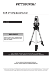
self-leveling laser level
Model 92703
Set up and Operating Instructions
Visit our website at: http://www.harborfreight.com
Read this material before using this product.
Failure to do so can result in serious injury.
Save this manual.
Copyright© 2005 by Harbor Freight Tools®. All rights reserved. No portion of this manual or any artwork
contained herein may be reproduced in any shape or form without the express written consent of
Harbor Freight Tools. Diagrams within this manual may not be drawn proportionally. Due to continuing
improvements, actual product may differ slightly from the product described herein. Tools required for
assembly and service may not be included.
For technical questions or replacement parts, please call 1-800-444-3353.
Revised Manual 10h
NOTICE is used to
address practices not
related to personal injury.
Save This Manual
Keep this manual for the safety warnings
and precautions, assembly, operating,
inspection, maintenance and cleaning
procedures. Write the product’s serial number
in the back of the manual near the assembly
diagram (or month and year of purchase if
product has no number). Keep this manual
and the receipt in a safe and dry place for
future reference.
Important SAFETY
Information
In this manual, on the labeling, and
all other information provided with
this product:
This is the safety alert
symbol. It is used to alert
you to potential personal
injury hazards. Obey all
safety messages that follow
this symbol to avoid possible
injury or death.
DANGER indicates a
hazardous situation
which, if not avoided, will result
in death or serious injury.
WARNING indicates a
hazardous situation
which, if not avoided, could
result in death or serious injury.
CAUTION, used with
the safety alert
symbol, indicates a hazardous
situation which, if not avoided,
could result in minor or moderate
injury.
CAUTION, without the
safety alert symbol, is
used to address practices not
related to personal injury.
General Safety Warnings
WARNING! Read all safety warnings
and instructions. Save all warnings
and instructions for future
reference.
Laser Light.
Avoid direct
eye exposure. The included laser
enhancement glasses are NOT
intended to protect your eyes in
any way.
1.
Do not direct the laser beam into the
eyes of any person or animal. Doing
so may cause severe injury to the eye.
2.
Verify Laser Level is in the “Off” position
before making any adjustments or
changing the batteries.
3.
Position batteries in proper polarity and
do not install batteries of different types,
charge levels, or capacities together.
4.
Remove batteries if Laser Level is not to
be used for a long period of time.
5.
The Laser Level is a delicate instrument;
do not drop or jar the Laser Level.
6.
Wear ANSI-approved safety goggles and
heavy-duty work gloves during use.
7.
Keep work area clean and well lit.
8.
This product is not a toy. Keep it out of
reach of children.
Rev 05c, 06b
Page 2
For technical questions, please call 1-800-444-3353.
SKU 92703
9.
Keep children and bystanders away
while operating Laser Level.
10. Inspect before every use; do not use if
parts loose or damaged.
11. Stay alert, watch what you are doing
and use common sense when operating
Laser Level. Do not use Laser Level
while you are tired or under the influence
of drugs, alcohol or medication.
Specifications
Laser Range
Projects Up to 40 ft.
Max. Tripod Height
48”
Self Leveling Range
6°
Batteries
(3) AAA (included)
DANGER
LASER LIGHT
AVOID DIRECT EYE EXPOSURE
Max. Output: <5 mW,
Wavelength: 650 nm ± 10 nm
12. Dress properly. Do not wear loose
clothing or jewelry. Keep your hair,
clothing and gloves away from moving
parts.
13. Maintain labels and nameplates on
the tool. These carry important safety
information. If unreadable or missing,
contact Harbor Freight Tools for a
replacement.
14. WARNING: This product contains or,
when used, produces a chemical known
to the State of California to cause cancer
and birth defects or other reproductive
harm. (California Health & Safety Code
§ 25249.5, et seq.)
15. The warnings, precautions, and
instructions discussed in this instruction
manual cannot cover all possible
conditions and situations that may occur.
It must be understood by the operator
that common sense and caution are
factors which cannot be built into this
product, but must be supplied by the
operator.
Save these
instructions.
SKU 92703
CLASS IIIa LASER PRODUCT
This product complies with
21 CFR 1040.10 and 1040.11
CEN-TECH
3491 Mission Oaks Blvd.,
Camarillo, CA, USA, 93011
Manufacture Date: ___________, _______
Unpacking
When unpacking, make sure that the
item is intact and undamaged. If any parts
are missing or broken, please call Harbor
Freight Tools at 1-800-444-3353 as soon as
possible.
Instructions for putting
into use
Read the entire Important
Safety Information
section at the beginning of this
manual including all text under
subheadings therein before set up
or use of this product.
To prevent
serious injury
from accidental
operation:
Turn the Power Switch to Off
before adjusting Laser Level.
Note: For additional information regarding the
parts listed in the following pages, refer
to the Assembly Diagram near the end of
this manual.
For technical questions, please call 1-800-444-3353.
Page 3
To prevent
serious injury
from accidental
operation: Turn Power Switch
to Off before adjusting Level.
Assembly
1.
Remove the tripod from the case.
2.
Open tripod’s legs and adjust positioning
of each leg until base is level. Use
bubble level in tripod base as a guide.
3.
Remove the Laser Level from the case.
4.
Install batteries, making sure to align
batteries according to indicated polarity.
5.
Attach the Laser to the tripod base. Do
this by threading the bolt at the top of the
tripod through the holes at the center of
the Laser Level’s lower base.
6.
Level the Laser by using the tri-brack
adjustment screws until the bubbles are
centered on the two levels.
7.
Loosen the brass screw located under
the center of the Laser Level’s upper
base until the pendulum lock is released.
8.
Turn on the Laser. Allow the laser lines
to stabilize for 4 to 6 seconds before
starting any measuring or leveling tasks.
9.
To disassemble and store, follow the
above directions in reverse. Please
note: Retighten the brass screw under
the Laser Level before continuing. This
will lock down the pendulum during
disassembly.
1.
After removing the Laser from the
Carrying Case, open the battery
compartment, insert the three “AA”
Batteries into the battery compartment
according to the polarity symbols
shown inside, and close the battery
compartment door.
2.
Be sure to set the Laser on as flat a
surface as possible. The tri-brack
adjustment on the base of the level can
be used to help level the unit. (Turn each
of the knobs to either raise or lower that
corner.) The self-leveling range of the
Laser is within ± 6°. Use the 2 Vials on
the base to verify that the base is level.
3.
Release the Pendulum Lock on the
bottom of the Laser Level, by loosening
the Brass screw in the center.
Operating Instructions
Read the entire Important
Safety Information
section at the beginning of this
manual including all text under
subheadings therein before set up
or use of this product.
Rev 05c, 05g, 07h
Page 4
For technical questions, please call 1-800-444-3353.
SKU 92703
4.
Press the button for the desired line(s)
2.
on the top of the unit to switch “on”. The
LED for the line will turn on when that
line is switched on.
Press both the horizontal and vertical
buttons to project a laser cross on wall
A. Mark point a1 at the intersection of the
beams. Turn the cross line laser 180°
and repeat on wall B, marking point b1 at
the intersection of the beams, see below.
5.
The Laser Level will work properly if it is
positioned within its self-leveling range.
3.
6.
Allow 4-6 seconds for the horizontal and
vertical Laser lines to be stabilized. After
stabilization, the Laser lines can be used
for measurement reference. Laser lines
may swing slightly due to vibration from
surroundings.
Move the instrument straight towards
wall A to a point 2 ft. away and repeat
step 2, marking the intersections as a2
and b2, see below.
7.
To prevent damage to the level, tighten
the pendulum lock after use and store in
the carrying case.
4.
a distance (da)=|a1 -a2|
b distance (db)=|b1 -b2|
If |da - db| <1mm, the accuracy is
within tolerance. Otherwise, return the
instrument to a qualified technician for
repair.
Accuracy Checking
NOTE: Due to the complicated, sensitive
nature of these procedures, ordinarily
only a qualified technician would attempt
them.
Level Beam Accuracy
1.
Set up the instrument with the
Tripod centered between two walls
approximately 16 ft. apart. Please ensure
the Rotary Base is level.
SKU 92703
Horizontal Beam Level Accuracy
(End to End)
1.
Set up the instrument with the Tripod
approximately 16 ft. from the wall.
Please ensure the Rotary Base is level.
2.
Press both the horizontal and vertical
buttons to project a laser cross on
the wall, mark point a 8 ft. from the
intersection of the beams to the right on
the horizontal beam.
3.
Turn the instrument until the vertical
beam has moved 16 ft. to the right side,
and mark b 8 ft. from the intersection of
For technical questions, please call 1-800-444-3353.
Page 5
the beams to the left on the horizontal
line.
8 ft.
8 ft.
a
After Using Laser
1.
Detach Laser from Tripod.
2.
Switch off both laser lines, horizontal and
vertical. Check to see that both indicator
LEDs are off.
3.
Lock Pendulum Lock by tightening the
screw in the center underneath the unit.
After use the Pendulum Lock should be
locked before the instrument is put away
in the Carrying Case.
4.
Note: When the Pendulum Lock is
unlocked, do not shake or strike the
instrument, otherwise the mechanism
inside could be damaged.
5.
Warning: Always make certain the Laser
is OFF before adjusting or changing
batteries.
b
16 ft.
4.
If the distance between a and b is less
than or equal to 2mm, the accuracy is
within tolerance. Otherwise, take the
instrument to a qualified technician for
repair.
Vertical Beam Level Accuracy (End to End)
1.
Set up the instrument with the Tripod,
approximately 16 ft. from the wall. (The
wall should be at least 17 ft. high).
Please ensure the Rotary Base is
approximately level.
2.
Press both the horizontal and vertical
buttons to project a laser cross on
the wall, mark point A 8 ft. above the
intersection of the beams on the vertical
beam.
3.
Use A as a starting point and nail one
end of a string with plumb bob (not
included) on A. The length of the string
should be 16 ft.
4.
Mark M1 16 ft. from point A on the string.
5.
Mark M2 8 ft. below the intersection of
the beams on the vertical line.
6.
Measure the distance between M1 and
M2.
7.
If the distance is less than or equal to
2 mm, the accuracy is within tolerance.
Otherwise, take the instrument to a
qualified technician for repair.
Page 6
For technical questions, please call 1-800-444-3353.
SKU 92703
Maintenance And
Servicing
Procedures not specifically
explained in this manual must
be performed only by a qualified
technician.
To prevent
serious injury
from accidental
operation:
Turn the OFF the Laser Level
before performing any
inspection, maintenance, or
cleaning procedures.
To prevent serious injury
from tool failure:
Do not use damaged equipment.
If abnormal noise or vibration
occurs, have the problem
corrected before further use.
Replacement Parts
NOTE: Internal replacement parts are not
available for this item.
Cleaning, Maintenance, and
Lubrication
1.
BEFORE EACH USE, inspect the
general condition Laser Level. Check for
loose hardware, misalignment or binding
of moving parts, cracked or broken parts,
and any other condition that may affect
its safe operation.
2.
After Use, wipe external surfaces of
the tool with clean cloth.
3.
Store the Laser Level indoors and out of
children’s reach.
Installing and Removing Batteries
1.
Remove the Battery Cover and insert
three new “AA” Alkaline Batteries. Follow
the polarity symbols so that the positive
and negative ends of the batteries match
the diagram.
2.
WARNING! Do not mix old and new
batteries. Remove batteries when storing
Laser.
PLEASE READ THE FOLLOWING CAREFULLY
The manufacturer and/or distributor has provided the parts list and assembly diagram in this manual as
a reference tool only. Neither the manufacturer or distributor makes any representation or warranty
of any kind to the buyer that he or she is qualified to make any repairs to the product, or that he or she
is qualified to replace any parts of the product. In fact, the manufacturer and/or distributor expressly
states that all repairs and parts replacements should be undertaken by certified and licensed technicians,
and not by the buyer. The buyer assumes all risk and liability arising out of his or her repairs to the
original product or replacement parts thereto, or arising out of his or her installation of replacement
parts thereto.
Rev 07h
SKU 92703
For technical questions, please call 1-800-444-3353.
Page 7
Parts List ANd Assembly Diagram
11
5
12
1
9
2
10
8
3
PART
DESCRIPTION
7
QUANTITY
1
Battery Cover
1
2
Plastic Body
1
3
Lock Screw
1
4
Tripod
1
5
Switch (Horizon)
1
6
Adjustable Handle
1
7
Base
1
8
Adjustable Screw
3
9
Laser Window
1
10
Bubble Vial
2
11
Laser Modules (Internal)
1
12
Switch (Vertical)
1
6
4
Record Product’s Serial Number Here:
Note:If product has no serial number, record month and year of purchase instead.
Note:Some parts are listed and shown for illustration purposes only, and are not available individually as
replacement parts.
Page 8
For technical questions, please call 1-800-444-3353.
Rev 07h
SKU 92703