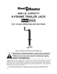
1
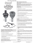
ROUTER TABLE FENCE
Model 97385
Set up And Operating Instructions
Diagrams within this manual may not be drawn proportionally.
Due to continuing improvements, actual product may differ slightly from the product described herein.
Distributed exclusively by Harbor Freight Tools®.
3491 Mission Oaks Blvd., Camarillo, CA 93011
Visit our website at: http://www.harborfreight.com
Read this material before using this product.
Failure to do so can result in serious injury.
Save this manual.
Copyright© 2007 by Harbor Freight Tools®. All rights reserved. No portion of this
manual or any artwork contained herein may be reproduced in any shape or form
without the express written consent of Harbor Freight Tools.
For technical questions or replacement parts, please call 1-800-444-3353.
Save This Manual
Notice
NOTICE is used to
address practices
not related to personal injury.
Keep this manual for the safety warnings and precautions, assembly, operating,
inspection, maintenance and cleaning procedures. Write the product’s serial number
in the back of the manual (or month and
year of purchase if product has no number). Keep this manual and the receipt in
a safe and dry place for future reference.
Caution
CAUTION, without
the safety alert
symbol, is used to address
practices not related to
personal injury.
General Safety Rules
Important SAFETY
Information
WARNING! Read all instructions
Failure to follow all instructions
listed below may result
in serious injury. The term
“equipment” in all of the warnings
listed below refers to your Router
Table Fence.
In this manual, on the labeling,
and all other information
provided with this product:
This is the safety alert
symbol. It is used to alert
you to potential personal
injury hazards. Obey all
safety messages that
follow this symbol to avoid
possible injury or death.
DANGER indicates
a hazardous
situation which, if not
avoided, will result in death or
serious injury.
SAVE THESE INSTRUCTIONS
1.
a.Keep work area clean and well lit.
Cluttered or dark areas invite accidents.
b.Keep children and bystanders away
while operating this equipment.
Distractions can cause you to lose
control.
Danger
WARNING
indicates a
hazardous situation which, if
not avoided, could result in
death or serious injury.
WARNING
CAUTION, used
with the safety
alert symbol, indicates a
hazardous situation which, if
not avoided, could result in
minor or moderate injury.
Caution
SKU 97385
Work area safety
2.
Personal safety
a.Stay alert, watch what you are doing
and use common sense when operating this equipment. Do not use
the Router Table Fence while you
are tired or under the influence of
drugs, alcohol or medication. A moment of inattention while operating
this equipment may result in serious
personal injury.
b.
Use safety equipment. Always wear eye protec-
tion. Safety equipment
such as dust mask, non-skid safety
For technical questions, please call 1-800-444-3353.
Page 2
shoes, hard hat, or hearing protection used for appropriate conditions
will reduce personal injuries.
c. Do not overreach. Keep proper footing and balance at all times. This
enables better control of the Router
Table Fence in unexpected situations.
d.Dress properly. Do not wear loose
clothing or jewelry. Keep your hair,
clothing and gloves away from moving parts. Loose clothes, jewelry or
long hair can be caught in moving
parts.
3.
of the Router Table Fence for operations different from those intended
could result in a hazardous situation.
4.
a.Maintain the Router Table Fence
according to the instructions on page
6 of this manual. Use only identical
replacement parts. This will ensure
that the safety of the equipment is
maintained.
Specific Safety Rules
1.
Maintain labels and nameplates on
the Router Table Fence. These carry
important safety information. If unreadable or missing, contact Harbor
Freight Tools for a replacement.
2.
This product is not a toy. Keep it out
of reach of children.
3.
Secure the Fence firmly to a router
table or drill press table before use.
4.
Read the manual of the router or drill
press used with the Fence before
use.
5.
Some dust created by power sanding, sawing, grinding, drilling, and
other construction activities, contains
chemicals known [to the State of California] to cause cancer, birth defects
or other reproductive harm. Some
examples of these chemicals are:
• Lead from lead-based paints
• Crystalline silica from bricks and cement or other masonry products
• Arsenic and chromium from chemically treated lumber
Your risk from these exposures varies, depending on how often you do
this type of work. To reduce your
exposure to these chemicals: work in
a well ventilated area, and work with
Equipment use and care
a.Do not force the Router Table Fence.
Use the correct equipment for your
application. The correct equipment
will do the job better and safer at the
rate for which it was designed.
b.Store idle equipment out of the
reach of children and do not allow
people unfamiliar with the Router
Table Fence or these instructions to
operate the equipment. This product
can be dangerous in the hands of
untrained users.
c. Maintain the Router Table Fence.
Check for misalignment or binding of
moving parts, breakage of parts and
any other condition that may affect
the equipment’s operation. If damaged, have the equipment repaired
before use. Many accidents are
caused by poorly maintained equipment.
d.Use the Router Table Fence in accordance with these instructions
and in the manner intended for the
particular type of equipment, taking
into account the working conditions
and the work to be performed. Use
SKU 97385
Service
For technical questions, please call 1-800-444-3353.
Page 3
approved safety equipment, such as
those dust masks that are specially
designed to filter out microscopic
particles. (California Health & Safety
Code § 25249.5, et seq.)
6.
possible.
Initial Set Up
Instructions
Read the entire Important
Safety Information section
at the beginning of this manual
including all text under
subheadings therein before set
up or use of this product.
The warnings, precautions, and instructions discussed in this instruction
manual cannot cover all possible conditions and situations that may occur.
It must be understood by the operator
that common sense and caution are
factors which cannot be built into this
product, but must be supplied by the
operator.
To prevent
serious injury
from accidental
operation:
Turn the Power Switch of the
router or drill press to its
“OFF” position and unplug
the tool from its electrical
outlet before assembling or
making any adjustments to
the Router Table Fence.
WARNING
Save these
instructions.
Specifications
Product Applications
May be used with most router
and drill press tables.
Construction/Material
Aluminum Stop
Steel Housing
Hose Adapter Size
2-1/2” Diameter
Overall Dimensions
25-1/4” L x 4-1/8” W x 4-1/8” H
Collapsed
Dimensions
36-3/4” L x 4-1/8” W x 4-1/8” H
Extended Fence
Dimensions
23-13/16” L x 2-1/8” W x 1-7/8”
H
Additional Features
T-Slots to Accept Featherboards
or Stops / Independently
Adjustable Fence Halves /
Fence Extension & Material
Stop
Unpacking
When unpacking, check to make sure that
the item is intact and undamaged. If any
parts are missing or broken, please call
Harbor Freight Tools at the number shown
on the cover of this manual as soon as
SKU 97385
Note: For additional information regarding
the parts listed in the following pages,
refer to the Assembly Diagram near
the end of this manual.
Assembly
To Install The Vacuum Attachment:
1.
Slide the head of two Carriage
Screws (13) into the center channel
of the Fence Slide (5) Repeat the
same procedure for the other Fence
Slide, but insert a Carriage Screw
(14) as well. Guide the four shorter
Screws into the center and adjacent
two holes in the Fence (1)
(See Assy. Diagram.)
For technical questions, please call 1-800-444-3353.
Page 4
2.
Insert the Vacuum attachment (12)
onto the center Screws. Attach one
Washer (15) onto each Screw. Attach
the Slide Knobs (10) to the Screws
and tighten. (See Assy. Diagram.)
Fence on a Router Bed, slide the two
Guides (2) onto the rails on the Router Bed. (See Assy. Diagram.)
3.
Insert the Extension Rods (2) into the
outer channels of the Fence Slide (5)
at the Fence (1) side.
(See Assy. Diagram.)
Operating Instructions
4.
Slide the head of the Carriage
Screws (14) into the center channel
of the End Slide (6).
(See Assy. Diagram.)
5.
Attach the Block Stop (7) to the
protruding Carriage Screw (14) while
aligning the tangs on the Block Stop
with the center channel face of the
Fence Slide (5). Attach a Flat Washer (15) and Knob (11) to the Screw
and tighten.
NOTE: The Block Stop slides
through the entire length of the Fence
Slide. Use the Block Stop for repetitive work. If not needed, loosen the
securing Knob (11) and slide the assembly off the Fence Guide (2).
(See Assy. Diagram.)
6.
7.
Attach the “C” Clamp (9) onto the
Carriage Screws (14), noting that
one end is locked into the slot in the
Fence (1) and the other end rests
on the Extension Rod (8). Attach
a Washer (15) and Knob (11) and
tighten. (See Assy. Diagram.)
Position a Guide (2) under the Fence
(1). Insert T-Screw (4) from underneath through Guide (2), Fence (1)
and Washer (15). Screw Lock Knob
(3) onto T-Screw (4) and tighten
clockwise. Attach the other Guide
using the same procedure. To attach and secure the Router Table
SKU 97385
Read the entire Important
Safety Information section
at the beginning of this manual
including all text under
subheadings therein before set
up or use of this product.
Tool Set Up
To prevent
serious injury
from accidental
operation: Make sure the
power switch of the router or
drill press is in its “OFF”
position and the machine is
unplugged from its electrical
outlet before performing any
set up procedures.
WARNING
1.
After the Router Table Fence is
mounted to the router/drill press table
top, adjust the Router Table Fence by
loosening the two Adjusting Screws
(3). (See Assy. Diagram.)
2.
Slide the Router Table Fence forward
or backward to where you need to
stop your material. Then tighten the
two Adjusting Screws (3) to secure
the Router Table Fence in place.
Always tighten both Adjusting Screws
to ensure a secure connection.
(See Assy. Diagram.)
3.
An additional adjustment may be
made to where you need to stop your
material. Loosen the Knob (11) on
For technical questions, please call 1-800-444-3353.
Page 5
the “C” Clamp (9). Slide the End
Slide (6) to the right or left along the
Fence Slides (5) to the point at which
you need to stop your material. Then
retighten the Knob (11) to secure the
End Slide (6) in place.
(See Assy. Diagram.)
4.
NOTE: The End Slide (6) may be inserted in either the left or right side of
the Fence Slides (5) depending upon
the application.
(See Assy. Diagram.)
Maintenance And
Servicing
Procedures not specifically
explained in this manual
must be performed only by a
qualified technician.
To prevent
serious injury
from accidental
operation:
Turn the Power Switch of the
router or drill press to its
“OFF” position and unplug
the machine from its electrical
outlet before performing any
inspection, maintenance, or
cleaning procedures.
WARNING
To prevent serious
injury from EQUIPMENT
failure:
Do not use damaged
equipment. If abnormal noise
or vibration occurs, have the
problem corrected before
further use.
SKU 97385
Inspection, Maintenance And Cleaning
1.
BEFORE EACH USE, inspect the
general condition of the Router Table
Fence. Check for loose screws, misalignment or binding of moving parts,
cracked or broken parts, damaged
and any other condition that may affect its safe operation.
2.
After Use, clean external surfaces
of the Router Table Fence with a
clean, moist cloth and mild detergent.
Then dry. Do not use solvents.
3.
WHEN STORING, keep the Router
Table Fence in a clean, dry, safe location out of reach of children and other
unauthorized people.
PLEASE READ THE
FOLLOWING CAREFULLY
The manufacturer and/or
distributor has provided the
parts list and assembly diagram in
this manual as a reference tool
only. Neither the manufacturer
or distributor makes any
representation or warranty of
any kind to the buyer that he
or she is qualified to make any
repairs to the product, or that he
or she is qualified to replace any
parts of the product. In fact, the
manufacturer and/or distributor
expressly states that all repairs
and parts replacements should
be undertaken by certified and
licensed technicians, and not by
the buyer. The buyer assumes all
risk and liability arising out of
his or her repairs to the original
product or replacement parts
thereto, or arising out of his or
her installation of replacement
parts thereto.
For technical questions, please call 1-800-444-3353.
Page 6
PARTS LIST
Part
Description
Q’ty
1
Fence
1
2
Guide
2
3
Lock Knob
2
4
T-Screw (1/4” x 3/4”)
2
5
Fence Slide
2
6
End Slide
1
7
Block Stop
1
8
Extension Rod
2
9
“C” Clamp
1
10
Slide Knob
4
11
Knob
2
12
Vacuum Attachment
1
13
Carriage Screw (1/4” x 20 x 3/4”)
5
14
Carriage Screw (1/4” x 20 x 1-1/4”)
1
15
Flat Washer (1/4”)
8
ASSEMBLY DIAGRAM
11
15
7
6
14
4
8
3
5
9
15
11
2
10
13
1
SKU 97385
15
12
For technical questions, please call 1-800-444-3353.
Page 7
LIMITED 90 DAY WARRANTY
Harbor Freight Tools Co. makes every effort to assure that its products meet high
quality and durability standards, and warrants to the original purchaser that this product is free from defects in materials and workmanship for the period of 90 days from
the date of purchase. This warranty does not apply to damage due directly or indirectly,
to misuse, abuse, negligence or accidents, repairs or alterations outside our facilities,
criminal activity, improper installation, normal wear and tear, or to lack of maintenance.
We shall in no event be liable for death, injuries to persons or property, or for incidental,
contingent, special or consequential damages arising from the use of our product. Some
states do not allow the exclusion or limitation of incidental or consequential damages, so
the above limitation of exclusion may not apply to you. This warranty is expressly in lieu of all other warranties, express or implied, including the
warranties of merchantability and fitness.
To take advantage of this warranty, the product or part must be returned to us with
transportation charges prepaid. Proof of purchase date and an explanation of the complaint must accompany the merchandise. If our inspection verifies the defect, we will either repair or replace the product at our election or we may elect to refund the purchase
price if we cannot readily and quickly provide you with a replacement. We will return repaired products at our expense, but if we determine there is no defect, or that the defect
resulted from causes not within the scope of our warranty, then you must bear the cost
of returning the product.
Record Product’s Serial Number Here:
Note: If product has no serial number, record month and year of purchase instead.
Note: Some parts are listed and shown for illustration purposes only, and are not available individually as replacement parts.
SKU 97385
For technical questions, please call 1-800-444-3353.
Page 8