1
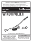
CORD REEL WORK LIGHT
(30 FOOT, FLUORESCENT)
Model 92156
ASSEMBLY AND OPERATING INSTRUCTIONS
®
TO PREVENT SERIOUS INJURY,
READ AND UNDERSTAND ALL WARNINGS
AND INSTRUCTIONS BEFORE USE.
3491 Mission Oaks Blvd., Camarillo, CA 93011
Visit our Web site at: http://www.harborfreight.com
Copyright 2004 by Harbor Freight Tools®. All rights reserved. No portion of this
manual or any artwork contained herein may be reproduced in any shape or form
without the express written consent of Harbor Freight Tools.
For technical questions and replacement parts, please call 1-800-444-3353.
PRODUCT SPECIFICATIONS
Cord Length
30 Feet (16 Ga.)
Maximum Bulb Wattage
13 Watts
Outlet Capacity
5 A/125 VAC
Weight
7.3 Lbs.
Features: 4’ Pigtail with overload protection, 13 Watt
Fluorescent Bulb, 3- Prong Socket in Handle,
E223040
GENERAL USE CORD REEL ONLY
FOR USE IN INDOOR DRY LOCATIONS ONLY
SAVE THIS MANUAL
You will need this manual for the safety warnings and precautions, assembly,
operating, inspection, maintenance and cleaning procedures, parts list and assembly diagram. Keep your invoice with this manual. Write the invoice number
on the inside of the front cover. Keep this manual and invoice in a safe and dry
place for future reference.
GENERAL SAFETY RULES
WARNING!
READ AND UNDERSTAND ALL INSTRUCTIONS
Failure to follow all instructions listed below may result in
electric shock, fire, and/or serious injury.
SAVE THESE INSTRUCTIONS
WORK AREA
1.
Keep your work area clean and well lit. Cluttered benches and dark areas
invite accidents.
2.
Do not operate power tools in explosive atmospheres, such as in the
presence of flammable liquids, gases, or dust. Power tools create sparks
which may ignite the dust or fumes.
3.
Keep bystanders, children, and visitors away while operating a power tool.
Distractions can cause you to lose control.
SKU 92156
For technical questions, please call 1-800-444-3353.
Page 2
ELECTRICAL SAFETY
4.
Grounded tools must be plugged into an outlet properly installed and
grounded in accordance with all codes and ordinances. Never remove the
grounding prong or modify the plug in any way. Do not use any adapter
plugs. Check with a qualified electrician if you are in doubt as to whether
the outlet is properly grounded. If the tools should electrically malfunction or
break down, grounding provides a low resistance path to carry electricity away
from the user.
5.
Double insulated tools are equipped with a polarized plug (one blade is
wider than the other). This plug will fit in a polarized outlet only one way. If
the plug does not fit fully in the outlet, reverse the plug. If it still does not
fit, contact a qualified electrician to install a polarized outlet. Do not
change the plug in any way. Double insulation
eliminates the need for the
three wire grounded power cord and grounded power supply system.
6.
Avoid body contact with grounded surfaces such as pipes, radiators,
ranges, and refrigerators. There is an increased risk of electric shock if your
body is grounded.
7.
Do not expose power tools to rain or wet conditions. Water entering a power
tool will increase the risk of electric shock.
8.
Do not abuse the Power Cord. Never use the Power Cord to carry the tools
or pull the Plug from an outlet. Keep the Power Cord away from heat, oil,
sharp edges, or moving parts. Replace damaged Power Cords immediately. Damaged Power Cords increase the risk of electric shock.
9.
When operating a power tool outside, use an outdoor extension cord
marked “W-A” or “W”. These extension cords are rated for outdoor use, and
reduce the risk of electric shock.
PERSONAL SAFETY
10.
Stay alert. Watch what you are doing, and use common sense when operating a power tool. Do not use a power tool while tired or under the influence of drugs, alcohol, or medication. A moment of inattention while operating power tools may result in serious personal injury.
11.
Dress properly. Do not wear loose clothing or jewelry. Contain long hair.
Keep your hair, clothing, and gloves away from moving parts.
SKU 92156
For technical questions, please call 1-800-444-3353.
Page 3
12.
Avoid accidental starting. Be sure the Power Switch is off before plugging
in. Carrying power tools with your finger on the Power Switch, or plugging in
power tools with the Power Switch on, invites accidents.
13.
Do not overreach. Keep proper footing and balance at all times. Proper
footing and balance enables better control of the power tool in unexpected
situations.
14.
Use safety equipment. Always wear eye protection. Dust mask, nonskid
safety shoes, hard hat, or hearing protection must be used for appropriate
conditions.
REEL USE AND CARE
15.
Use the correct cord for your application. The correct cord will do the job
better and safer at the rate for which it is designed. NEVER exceed the maximum amperage (5 A), or voltage (125 VAC) from the receptacle.
16.
Do not use the power lamp if the Power Switch does not turn it on or off.
Any product that cannot be controlled with the Power Switch is dangerous and
must be replaced.
17.
Disconnect the Power Cord Plug from the power source before making any
adjustments, changing accessories, or installing this cord reel.
18.
Store idle tools out of reach of children and other untrained persons. Tools
are dangerous in the hands of untrained users.
19.
Maintain tools with care. Do not use a damaged product. Tag damaged products “Do not use” until repaired.
20.
Before use, check for misalignment or binding of moving parts, breakage of
parts, insecure mounting, and any other condition that may affect the reel’s
operation. If damaged, have the reel serviced before using. Many accidents
are caused by poorly maintained products.
21.
Use only accessories that are recommended by the manufacturer for your
model. Accessories that may be suitable for one tool may become hazardous
when used on another tool.
SERVICE
22.
Reel service must be performed only by qualified repair personnel. Service
or maintenance performed by unqualified personnel could result in a risk of injury.
SKU 92156
For technical questions, please call 1-800-444-3353.
Page 4
23.
When servicing a reel, use only identical replacement parts. Follow
instructions in the “Inspection, Maintenance, And Cleaning” section of this
manual. Use of unauthorized parts or failure to follow maintenance instructions
may create a risk of electric shock or injury.
SPECIFIC SAFETY RULES
1.
Maintain labels and nameplates on the Cord Reel Work Light. These carry
important information. If unreadable or missing, contact Harbor Freight Tools for
a replacement.
2.
Always wear ANSI approved safety impact eye goggles when installing the
Cord Reel Work Light. Using personal safety devices reduce the risk for injury.
Safety impact eye goggles are available from Harbor Freight Tools.
3.
Risk of fire. Never install a bulb that uses more than 13 watts or install a different type of bulb.
4.
Keep the Cord Reel Work Light dry. Never immerse the light or Cord Reel in
liquid.
5.
Always unplug the Cord Reel from its electrical outlet and allow it to cool
completely before performing any inspection, maintenance, or cleaning
procedures.
6.
The Cord Reel must be properly installed before connecting to the power
supply.
7.
Check for frayed or broken wires before each use.
8.
When pulling cord from the Cord Reel, always grasp the cord itself, and not
the device or tool the cord is plugged into.
9.
If mounted in an area that is not readily accessible, only connect this Cord
Reel to a switch-controlled outlet; then, if a malfunction occurs, the Reel
can be disconnected immediately.
SKU 92156
For technical questions, please call 1-800-444-3353.
Page 5
GROUNDING
WARNING!
Improperly connecting the grounding wire can result in the risk of electric
shock. Check with a qualified electrician if you are in doubt as to whether the
outlet is properly grounded. Do not modify the power cord plug provided with
the tool. Never remove the grounding prong from the plug. Do not use the
tool if the power cord or plug is damaged. If damaged, have it repaired by
a service facility before use. If the plug will not fit the outlet, have a proper
outlet installed by a qualified electrician.
GROUNDED TOOLS: TOOLS WITH THREE PRONG PLUGS
1.
Tools marked with “Grounding Required” have a three wire cord and three prong
grounding plug. The plug must be connected to a properly grounded outlet. If
the tool should electrically malfunction or break down, grounding provides a low
resistance path to carry electricity away from the user, reducing the risk of electric shock. (See Figure A.)
2.
The grounding prong in the plug is connected through the green wire inside the
cord to the grounding system in the tool. The green wire in the cord must be the
only wire connected to the tool’s grounding system and must never be attached
to an electrically “live” terminal. (See Figure A.)
3.
Your tool must be plugged into an appropriate outlet, properly installed and
grounded in accordance with all codes and ordinances. The plug and outlet
should look like those in the following illustration. (See Figure A.)
FIGURE A
SKU 92156
For technical questions, please call 1-800-444-3353.
Page 6
DOUBLE INSULATED TOOLS: TOOLS WITH TWO PRONG PLUGS
4.
Tools marked “Double Insulated” do not require grounding. They have a special
double insulation system which satisfies OSHA requirements and complies with
the applicable standards of Underwriters Laboratories, Inc., the Canadian
Standard Association, and the National Electrical Code. (See Figure B.)
5.
Double insulated tools may be used in either of the 120 volt outlets shown in the
following illustration. (See Figure B.)
FIGURE B
EXTENSION CORDS
1.
Grounded tools require a three wire extension cord. Double Insulated tools
can use either a two or three wire extension cord.
2.
As the distance from the supply outlet increases, you must use a heavier gauge
extension cord. Using extension cords with inadequately sized wire causes a
serious drop in voltage, resulting in loss of power and possible tool damage.
(See Figure C, next page.)
3.
The smaller the gauge number of the wire, the greater the capacity of the cord.
For example, a 14 gauge cord can carry a higher current than a 16 gauge cord.
(See Figure C.)
4.
When using more than one extension cord to make up the total length, make
sure each cord contains at least the minimum wire size required.
(See Figure C.)
5.
If you are using one extension cord for more than one tool, add the nameplate
amperes and use the sum to determine the required minimum cord size.
(See Figure C.)
SKU 92156
For technical questions, please call 1-800-444-3353.
Page 7
6.
If you are using an extension cord outdoors, make sure it is marked with the
suffix “W-A” (“W” in Canada) to indicate it is acceptable for outdoor use.
7.
Make sure your extension cord is properly wired and in good electrical condition.
Always replace a damaged extension cord or have it repaired by a qualified
electrician before using it.
8.
Protect your extension cords from sharp objects, excessive heat, and damp or
wet areas.
RECOMMENDED MINIMUM WIRE GAUGE FOR EXTENSION CORDS*
(120 VOLT)
NAMEPLATE
AMPERES
(At Full Load)
EXTENSION CORD LENGTH
25 FEET
0 - 2.0
2.1 - 3.4
3.5 - 5.0
5.1 - 7.0
7.1 - 12.0
12.1 - 16.0
16.1 - 20.0
FIGURE C
50 FEET
75 FEET
100 FEET
150 FEET
18
18
18
16
14
12
10
16
16
16
14
12
10
-
16
14
14
12
10
-
16
14
12
12
-
18
18
18
18
16
14
12
*Based on limiting the line voltage drop
to five volts at 150% of the rated amperes.
SYMBOLOGY
Double Insulated
Canadian Standards
Association
Underwriters
Laboratories, Inc.
V~
A
no
xxxx/min.
SKU 92156
Volts Alternating Current
Amperes
No Load Revolutions
per Minute (RPM)
For technical questions, please call 1-800-444-3353.
Page 8
UNPACKING
When unpacking, check to make sure all the parts shown on the Parts List on page 12
are included. If any parts are missing or broken, please call Harbor Freight Tools at the
number shown on the cover of this manual as soon as possible.
OPERATING INSTRUCTIONS
NOTE: For additional information regarding the parts listed in the following pages, refer
to the Assembly Diagram on page 13.
1.
CAUTION: Always make sure the Power Cord of the Cord Reel Work Light is
unplugged from its electrical outlet prior to making any adjustments to the tool.
2.
When deciding where to hang your Cord Reel Work Light, make sure the Plug to
the AC outlet will reach a power outlet. Make sure the hook you are hanging the
Cord Reel Work Light from is secured in a stud or rafter that is capable of holding
the full weight of the Cord Reel Work Light, and the stress associated with pulling
out and retracting the Cord. See FIGURE 1.
FIGURE 1
Hang Cord Reel from here
Circuit Breaker (14)
Hook (25)
Hook (21)
Switch (29)
SKU 92156
For technical questions, please call 1-800-444-3353.
Page 9
OPERATING INSTRUCTIONS
3.
Hang the Cord Reel Work Light and plug it in to an outlet.
4.
Pull on the Cord until it reaches the desired length and then let it slightly retract
until it locks into place.
5.
You may slide the Hook (25) along the Cord to hang the Cord, keeping it out of
the way. Also, you may use the Hook (21) to hang the Cord Reel Work Light,
allowing for hands free operation. See FIGURE 1.
6.
To turn on the light, press the Switch (29) to the “I” position (see FIGURE 1). To
turn it off, press the Switch (29) to the “O” position. When you use the Built-in
Socket (23), make sure that the tool or appliance is rated below the Cord’s 5
Amp, 625 Watt rating.
Note: If the tool stops for no apparent reason, disconnect any tool from the outlet, and
briefly press the Circuit Breaker Button. The tool attached may have exceeded
the capacity of the reel. If the power to the tool keeps cutting out, have the reel
inspected and repaired by a qualified technician before further use. NEVER
hold down or disable the Circuit Breaker button; doing so may cause a fire.
See FIGURES 1 and 2.
FIGURE 2
7.
Circuit Breaker (14) Button
To return the Cord to the Cord Reel, pull forward and release, allowing the Cord
to slowly retract back into the unit.
INSPECTION, MAINTENANCE, AND CLEANING
1.
WARNING! Make sure the Power Switch of the Cord Reel Light is in its
“OFF” position and that the tool is unplugged from its electrical outlet before
performing any inspection, maintenance, or cleaning procedures.
2.
BEFORE EACH USE, inspect the general condition of the Cord Reel Light.
Check for loose screws, misalignment or binding of moving parts, cracked or
broken parts, damaged electrical wiring, and any other condition that may affect
its safe operation. If abnormal noise or vibration occurs, have the problem corrected before further use. Do not use damaged equipment.
3.
Wipe down the unit with a lint free cloth.
SKU 92156
For technical questions, please call 1-800-444-3353.
Page 10
INSPECTION, MAINTENANCE, AND CLEANING (cont’d)
4.
Check the Cord for frays, tears, or cracks. Have the Cord replaced by an authorized technician if necessary.
5.
To change the Bulb (31):
• Remove the Clear Cover (15) by removing the Screws (16) and gently pulling
it off. See FIGURES 3 and 4.
• Remove the Bulb Protector (27) from the old Bulb. Gently fit the Bulb Protector (27) over the new Bulb (31). See FIGURE 5.
• Gently snap the new Bulb (31) into the receptacle. See FIGURE 6.
• Replace the Clear Cover (15) and the Screws (16).
FIGURE 3
FIGURE 4
FIGURE 5
FIGURE 6
Bulb (31)
Receptacle
Bulb Protector (27)
SKU 92156
For technical questions, please call 1-800-444-3353.
Page 11
PARTS LIST
Part
1
2
3
4
5
6
7
8
9
10
11
12
13
14
15
16
17
18
19
20
21
22
23
24
25
26
27
28
29
30
31
32
Description
Left Cover
Ratchet Pawl
Gear
Plate
Spring
Drum
Drum
Positive Plate
Negative Plate
Loop
Bracket
Right Cover
Bracket
Circuit Breaker
Clear Cover
Screw (2 Qty.)
Screw (5 Qty.)
Left Housing
Lamp Ballast
Stop Ball
Hook
Socket
Built-in Socket
Hook Connector
Hook
Rod
Bulb Protector
Right Housing
Switch
Reflector
Bulb (110V, 13 Watt)
Cord Clamp
PLEASE READ THE FOLLOWING CAREFULLY
THE MANUFACTURER AND/OR DISTRIBUTOR HAS PROVIDED THE PARTS LIST AND ASSEMBLY
DIAGRAM IN THIS MANUAL AS A REFERENCE TOOL ONLY. NEITHER THE MANUFACTURER OR
DISTRIBUTOR MAKES ANY REPRESENTATION OR WARRANTY OF ANY KIND TO THE BUYER THAT
HE OR SHE IS QUALIFIED TO MAKE ANY REPAIRS TO THE PRODUCT, OR THAT HE OR SHE IS
QUALIFIED TO REPLACE ANY PARTS OF THE PRODUCT. IN FACT, THE MANUFACTURER AND/
OR DISTRIBUTOR EXPRESSLY STATES THAT ALL REPAIRS AND PARTS REPLACEMENTS SHOULD
BE UNDERTAKEN BY CERTIFIED AND LICENSED TECHNICIANS, AND NOT BY THE BUYER. THE
BUYER ASSUMES ALL RISK AND LIABILITY ARISING OUT OF HIS OR HER REPAIRS TO THE
ORIGINAL PRODUCT OR REPLACEMENT PARTS THERETO, OR ARISING OUT OF HIS OR HER
INSTALLATION OF REPLACEMENT PARTS THERETO.
SKU 92156
For technical questions, please call 1-800-444-3353.
Page 12
ASSEMBLY DIAGRAM
NOTE: Some parts are listed and shown for illustration purposes only, and are not
available individually as replacement parts.
SKU 92156
For technical questions, please call 1-800-444-3353.
Page 13