1
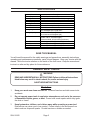
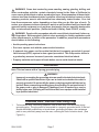
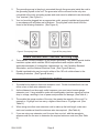
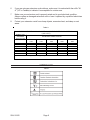
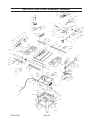
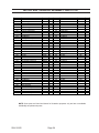
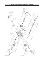
TABLE SAW - 10 INCH
DIRECT DRIVE
91815
ASSEMBLY AND OPERATING INSTRUCTIONS
3491 MISSION OAKS BLVD., CAMARILLO, CA 93011
VISIT OUR WEB SITE AT HTTP://WWW.HARBORFREIGHT.COM
Copyright © 2004 by Harbor Freight Tools®. All rights reserved. No portion of
this manual or any artwork contained herein may be reproduced in any shape
or form without the express written consent of Harbor Freight Tools.
For technical questions and replacement parts, please call 1-800-444-3353
SPECIFICATIONS
Item
Power Requirements
Power Cord
Switch Type
Motor Capacity
Drive Type
Saw Blade
Arbor Size
Cutting Angles
Cutting Capacity
Rip Fence
Base Dimensions
Table Dimensions
Overall Dimensions
Weight
Description
115 VAC, 15 amps, 60 Hz
Length: 43 inches; 14 AWG x 3C, 3-prong plug
Toggle with pull-out key safety lock
1.5 HP, 5000 RPM (maximum)
Gear drive
10 inch, 36 teeth (included)
5/8 inch
90 to 30 degrees (left / right) angle
0 to 60 degree (left / right) miter
3-1/8 inches at 90 degrees;
2-1/8 inches at 45 degrees (tilt)
28-1/4 (L) x 1-3/4 (W) x 2-1/2 (H) inch
Scale: 0 to 27-1/4 inches (right)
Fence-to-blade: 25-1/2 inches (maximum)
20-1/8 (L) x 22-5/8 (W) x 21-5/8 (H) inches
38-1/2 (W) x 22-1/4 (L) x 1-3/8 (H) inches
20-1/8 (L) x 51-1/8 (W) x 38 (H) inches
165 lbs.
SAVE THIS MANUAL
You will need the manual for the safety warnings and precautions, assembly instructions,
operating and maintenance procedures, parts list and diagram. Keep your invoice with this
manual. Write the invoice number on the inside of the front cover. Keep the manual and
invoice in a safe and dry place for future reference.
GENERAL SAFETY RULES
WARNING!
READ AND UNDERSTAND ALL INSTRUCTIONS. Failure to follow all instructions
listed below may result in electric shock, fire, and/or serious injury.
SAVE THESE INSTRUCTIONS
Work Area
1.
Keep your work area clean and well lit. Cluttered benches and dark areas invite
accidents.
2.
Do not operate power tools in explosive atmospheres, such as in the presence
of flammable liquids, gases, or dust. Power tools create sparks which may ignite
the dust or fumes.
3.
Keep bystanders, children, and visitors away while operating a power tool.
Distractions can cause you to lose control. Protect others in the work area from
debris such as chips and sparks. Provide barriers or shields as needed.
SKU 91815
Page 2
Electrical Safety
4.
Avoid body contact with grounded surfaces such as pipes, radiators, ranges,
and refrigerators. There is an increased risk of electric shock if your body is
grounded.
5.
Do not expose power tools to rain or wet conditions. Water entering a power tool
will increase the risk of electric shock.
6.
Grounded tools must be plugged into an outlet properly installed and grounded
in accordance with all codes and ordinances. Never remove the grounding
prong or modify the plug in any way. Do not use any adapter plugs. Check with
a qualified electrician if you are in doubt as to whether the outlet is properly
grounded. If the tools should electrically malfunction or break down, grounding
provides a low resistance path to carry electricity away from the user.
7.
Double insulated tools are equipped with a polarized plug (one blade is wider
than the other). This plug will fit in a polarized outlet only one way. If the plug
does not fit fully in the outlet, reverse the plug. If it still does not fit, contact a
qualified electrician to install a polarized outlet. Do not change the plug in any
way. Double insulation
eliminates the need for the three wire grounded power
cord and grounded power supply system.
8.
Do not abuse the Power Cord. Never use the Power Cord to carry the tools or
pull the Plug from an outlet. Keep the Power Cord away from heat, oil, sharp
edges, or moving parts. Replace damaged Power Cords immediately. Damaged
Power Cords increase the risk of electric shock.
9.
When operating a power tool outside, use an outdoor extension cord marked
“W-A” or “W”. These extension cords are rated for outdoor use, and reduce the risk
of electric shock.
Personal Safety
10.
Stay alert. Watch what you are doing, and use common sense when operating a
power tool. Do not use a power tool while tired or under the influence of drugs,
alcohol, or medication. A moment of inattention while operating power tools may
result in serious personal injury.
11.
Dress properly. Do not wear loose clothing or jewelry. Contain long hair. Keep
your hair, clothing, and gloves away from moving parts. Loose clothes, jewelry, or
long hair can be caught in moving parts.
12.
Avoid accidental starting. Be sure the Power Switch is off before plugging in.
Carrying power tools with your finger on the Power Switch, or plugging in power tools
with the Power Switch on, invites accidents.
13.
Remove adjusting keys or wrenches before turning the power tool on. A wrench
or a key that is left attached to a rotating part of the power tool may result in personal
injury.
SKU 91815
Page 3
14.
Do not overreach. Keep proper footing and balance at all times. Proper footing
and balance enables better control of the power tool in unexpected situations.
15.
Use safety equipment. Always wear eye protection. Dust mask, nonskid safety
shoes, hard hat, or hearing protection must be used for appropriate conditions.
Tool Use and Care
16.
Use clamps (not included) or other practical ways to secure and support the
workpiece to a stable platform. Holding the work by hand or against your body is
unstable and may lead to loss of control.
17.
Do not force the tool. Use the correct tool for your application. The correct tool
will do the job better and safer at the rate for which it is designed.
18.
Do not use the power tool if the Power Switch does not turn it on or off. Any tool
that cannot be controlled with the Power Switch is dangerous and must be replaced.
19.
Disconnect the Power Cord Plug from the power source before making any
adjustments, changing accessories, or storing the tool. Such preventive safety
measures reduce the risk of starting the tool accidentally.
20.
Store idle tools out of reach of children and other untrained persons. Tools are
dangerous in the hands of untrained users.
21.
Maintain tools with care. Keep cutting tools sharp and clean. Properly
maintained tools with a sharp cutting edge are less likely to bind and are easier to
control. Do not use a damaged tool. Tag damaged tools “Do not use” until repaired.
22.
Check for misalignment or binding of moving parts, breakage of parts, and any
other condition that may affect the tool’s operation. If damaged, have the tool
serviced before using. Many accidents are caused by poorly maintained tools.
23.
Use only accessories that are recommended by the manufacturer for your
model. Accessories that may be suitable for one tool may become hazardous when
used on another tool.
Service
24.
Tool service must be performed only by qualified repair personnel. Service or
maintenance performed by unqualified personnel could result in a risk of injury.
25.
When servicing a tool, use only identical replacement parts. Follow
instructions in the “Inspection, Maintenance, And Cleaning” section of this
manual. Use of unauthorized parts or failure to follow maintenance instructions may
create a risk of electric shock or injury.
SKU 91815
Page 4
SPECIFIC SAFETY RULES FOR THE TABLE SAW
1.
Maintain labels and nameplates on the Table Saw. These carry important information.
If unreadable or missing, contact Harbor Freight Tools for a replacement.
2.
Always wear ANSI approved safety impact eye goggles and heavy work gloves when
using the Table Saw. Using personal safety devices reduce the risk for injury. Safety
impact eye goggles and heavy work gloves are available from Harbor Freight Tools.
3.
Maintain a safe working environment. Keep the work area well lit. Make sure there is
adequate surrounding workspace. Always keep the work area free of obstructions,
grease, oil, trash, and other debris. Do not use a power tool in areas near flammable
chemicals, dusts, and vapors. Do not use this product in a damp or wet location.
4.
Avoid unintentional starting. Make sure you are prepared to begin work before turning
on the Table Saw.
5.
Do not force the Table Saw. This tool will do the work better and safer at the speed
and capacity for which it was designed.
6.
Always unplug the Table Saw from its electrical outlet before performing and
inspection, maintenance, or cleaning procedures.
7.
After cutting, wait until the saw blade comes to a complete stop before removing stock
from the table, reaching around the saw blade, or leaving the area.
8.
Never walk away and leave the saw running.
9.
When making rip cuts, feed the stock into the blade against the direction of the blade
rotation.
10.
Always use a push stick (not included) when ripping small or thin stock.
11.
Keep saw blade sharp and free of all rust and pitch.
12.
Always use the Anti-kickback Pawl (17) attachment when making rip cuts.
13.
Always use the saw fence, blade guard, splitter, and anti-kickback fingers for
lengthwise sawing. Never push stock being cut by hand. Never disable the Blade
Guard (10).
14.
Tighten and lock all adjusting (saw blade positioning) screws before operating.
15.
Keeps hands out of the path of the saw blade during operation.
16.
(1)inch saw blades with 5/8 inch arbor on this machine.
Only use ten (10)
17.
Always secure the stock being cut with clamps whenever possible.
18.
Make sure that the Switch is in the OFF position before plugging the line cord into the
electrical outlet.
19.
Never cut more than one piece of stock at a time, for any type of cut.
20.
Provide proper support for the stock based on its size and the type of operation to be
performed.
SKU 91815
Page 5
21.
Many saw accidents are caused by dull, badly set, and improperly filed cutting blades;
gum or resin adhering to the cutting blade; and by saw blade misalignment with the
fence. Such conditions can cause the stock to stick, jam, stall the saw blade, or kick
back at the operator. Never cut anything other than wood with the included Saw
Blade; cutting hard materials can cause the carbide blade to shatter and break apart.
WARNING: Never attempt to free a stalled saw blade without first turning OFF the Table
Saw and unplugging the Line Cord from the outlet.
22.
Avoid awkward hand positions (i.e., crossing arms during operation) in which a
sudden slip could cause your hand to move into the moving saw blade.
23.
Before making any adjustments to the Table Saw, the Switch should be in the OFF
position and the Switch locked OFF.
24.
Never turn the Table Saw ON before clearing the table and work surface of all objects
(tools, scraps of wood, etc.), except the stock to be cut.
25.
Avoid Kickback of stock:
- For rip cuts, the saw blade must be exactly parallel to the fence to prevent pinching
or heeling. Use the stock Separator (27) on the output side of the stock cut.
- Only feed the stock against the rotation of the saw blade.
- Keep the stock firmly on the table while cutting.
26.
When making rip cuts:
- Push only on the main section of stock, between the saw blade and the fence.
- Always use a push stick, never your hands.
- Do not release the stock before the cut is complete, and push beyond the saw blade.
- Always push the stock through the saw blade, never pull it through from the opposite
direction.
- Always use the anti-kickback claws.
- Do not rip stock that is bowed, warped, or has nonparallel edges.
- Never reach over or behind the saw blade.
27.
The use of abrasive, cut off, or wire wheels can be dangerous and must not be used.
28.
Never perform any sawing operation freehand.
29.
Before each use, check all nuts, bolts, and screws for tightness. Vibration during
cutting may cause these to loosen.
30.
Keep extension cord off the ground and away from water.
Note: Performance of this tool may vary depending on variations in local line voltage. Extension cord usage may also affect tool performance.
SKU 91815
Page 6
WARNING! Some dust created by power sanding, sawing, grinding, drilling, and
other construction activities, contain chemicals known (to the State of California) to
cause cancer, birth defects or other reproductive harm. Some examples of these chemicals are: lead from lead-based paints, crystalline silica from bricks and cement or other
masonry products, arsenic and chromium from chemically treated lumber. Your risk
from these exposures varies, depending on how often you do this type of work. To
reduce your exposure to these chemicals: work in a well ventilated area, and work with
approved safety equipment, such as those dust masks that are specially designed to
filter out microscopic particles. (California Health & Safety Code 25249.5, et seq.)
WARNING! People with pacemakers should consult their physician(s) before using this product. Electromagnetic fields in close proximity to a heart pacemaker could
cause interference to, or failure of the pacemaker. In addition, people with pacemakers
should adhere to the following:
• Avoid operating power tools alone.
• Don’t use a power tool with the power switch locked on.
• If powered via a power cord be certain that the tool is properly grounded. A ground
fault interrupt (GFCI) system is also a good precaution. This inexpensive device is
a good safety measure because it prevents a sustained electrical shock.
• Properly maintain and inspect all tools before use to avoid electrical shock.
GROUNDING
Note: This tool comes with a 3-prong grounded plug.
WARNING!
Improperly connecting the grounding wire can result in the risk of electric shock.
Check with a qualified electrician if you are in doubt as to whether the outlet is
properly grounded. Do not modify the power cord plug provided with the tool or
product. Never remove the grounding prong from the plug. Do not use the tool if
the power cord or plug is damaged. If damaged, have it repaired by a service
facility before use. If the plug will not fit the outlet, have a proper outlet installed
by a qualified electrician.
Grounded Tools: Tools with Three Prong Plugs
1.
Tools marked with “Grounding Required” have a three wire cord and three prong
grounding plug. The plug must be connected to a properly grounded outlet. If the tool
should electrically malfunction or break down, grounding provides a low resistance
path to carry electricity away from the user, reducing the risk of electric shock. (See
Figure A.)
SKU 91815
Page 7
2.
The grounding prong in the plug is connected through the green wire inside the cord to
the grounding system in the tool. The green wire in the cord must be the only wire
connected to the tool’s grounding system and must never be attached to an electrically
“live” terminal. (See Figure A.)
3.
Your tool must be plugged into an appropriate outlet, properly installed and grounded
in accordance with all codes and ordinances. The plug and outlet should look like
those in the following illustration. (See Figure A.)
Figure A. Three-prong Outlet
Figure B. Two-prong Outlet
Double Insulated Tools: Tools with Two Prong Plugs
4.
Tools marked “Double Insulated” do not require grounding. They have a special double
insulation system which satisfies OSHA requirements and complies with the
applicable standards of Underwriters Laboratories, Inc., the Canadian Standard
Association, and the National Electrical Code. (See Figure B above.)
5.
Double insulated tools may be used in either of the 120 volt outlets shown in the
following illustration. (See Figure B above.)
EXTENSION CORDS
1.
Grounded tools require a three wire extension cord. Double Insulated tools can use
either a two or three wire extension cord.
2.
As the distance from the supply outlet increases, you must use a heavier gauge
extension cord. Using extension cords with inadequately sized wire causes a serious
drop in voltage, resulting in loss of power and possible tool damage. (See Table A.)
3.
The smaller the gauge number of the wire, the greater the capacity of the cord. For
example, a 14 gauge cord can carry a higher current than a 16 gauge cord. (See
Table A.)
4.
When using more than one extension cord to make up the total length, make sure
each cord contains at least the minimum wire size required. (See Table A.)
5.
If you are using one extension cord for more than one tool, add the nameplate
amperes and use the sum to determine the required minimum cord size. (See Table
A.)
SKU 91815
Page 8
6.
If you are using an extension cord outdoors, make sure it is marked with the suffix “WA” (“W” in Canada) to indicate it is acceptable for outdoor use.
7.
Make sure your extension cord is properly wired and in good electrical condition.
Always replace a damaged extension cord or have it repaired by a qualified electrician
before using it.
8.
Protect your extension cords from sharp objects, excessive heat, and damp or wet
areas.
Table A
RECO M M ENDED M INIM UM W IRE G AUG E FO R EXTENSIO N CO RDS*
(120 VO LT)
NAM EPLATE
AM PER ES
(At Full Load)
0 – 2.0
2.1 – 3.4
3.5 – 5.0
5.1 – 7.0
7.1 – 12.0
12.1 – 16.0
16.1 – 20.0
* Based
EXTENSIO N CO R D LENG TH
25
50
75
100
150
Feet
Feet
Feet
Feet
Feet
18
18
18
18
16
18
18
18
16
14
18
18
16
14
12
18
16
14
12
12
16
14
12
10
14
12
10
12
10
on lim iting the line voltage drop to five volts at 150% of the rated am peres.
SYMBOLOGY
Table B
(1)
SKU 91815
Page 9
UNPACKING
When unpacking, check to make sure that all the parts are included. Refer to the Assembly
section, and the Assembly Drawing and Parts List at the end of this manual.
If any parts are missing or broken, please call Harbor Freight Tools at the number on the
cover of this manual as soon as possible.
ASSEMBLY INSTRUCTIONS
Stand Assembly
Note: Hand tighten the nuts and bolts during assembly.
1.
Attach the Stand Legs (62) to the Stand Top (60) front and rear pieces using sixteen 5/
16” x 5/8” Carriage Bolts (61), 5/16” Flat Washers (59), 5/16” Lock Washers (39), and 5/
16” Hex Nuts (58). Refer to Figure C., below.
2.
Attach the Cross Braces (63) to the left and right sides of the Stand Legs (62), and
Cross Braces (64) to the front and rear sides of the Stand Legs (62). Use eight 5/16” x
5/8” Carriage Bolts (61), 5/16” Flat Washers (59), 5/16” Lock Washers (39), and 5/16”
Hex Nuts (58).
The longer Cross Braces must be under the longer Stand Top pieces as shown below.
Figure C. Stand Assembly
SKU 91815
Page 10
Assembling the Saw to the Stand
Caution: The Table Saw body is very heavy and needs two people to lift. Use care when
lifting. Failure to comply may cause serious injury and damage to equipment.
1.
With the help of another person, carefully lift the saw body out of the shipping box and
set on the ground.
2.
Remove the protect wrapping from the saw top and wipe the saw top clean with a soft
cloth.
3.
Lift the saw body and place upside down on a protective surface (For example, place
on a flattened cardboard box.).
4.
Place the previously assembled Stand upside down on the saw body bottom. Note
that the label on the Stand must face forward or toward the front of the saw body.
5.
Align the mounting holes in the Stand with those on the saw body bottom and secure
using four 5/16” x 3/4” Cap Bolts (38), eight 5/16 x 23mm Flat Washers (45), four
5/16” Lock Washers (39), and four 5/16” Hex Nuts (58). Refer to Figure D., below.
6.
Securely tighten the hardware attaching the saw body to the Stand. Do not tighten the
Stand hardware until the saw is placed on its feet.
7.
With the help of another person, carefully lift and turn the saw over onto the Stand
feet.
8.
Level the saw body by moving it back and forth until the saw body is sitting level and
squarely on the Stand feet.
9.
Securely tighten all Stand hardware.
Figure D. Stand-to-Saw Assembly
SKU 91815
Page 11
Extension Wing Assembly
1.
Bolt the right Extension Wing (76) to the Table (22) with three 5/16” x 1” Hex Cap Bolts
(75), 5/16 x 23mm Flat Washers (45), and 5/16” Lock Washers (39). Refer to Figures
E and F, below.
Hand tighten enough to hold the wing in place and allow for adjustment.
2.
Place a “carpenter’s level” (not included) on the Table so that it hangs over the edge of
the wing approximately one inch.
3.
Bring the edge of the wing flush to the edge of the Table top, then tighten the Hex Cap
Bolts when the (corner) lead edge of the wing is also flush with the Table from front to
back.
4.
Repeat steps one through four with the left Extension Wing (76).
Left Extension Wing (76)
Right Extension Wing (76)
Figure E. Wing Assembly
Figure F. Wing and Rail Assembly
SKU 91815
Page 12
Guide Rail Assembly
1.
Attach the Front Rail brackets (72 and 69) to the Table (22) with only three 1/4” x 3/4”
Hex Screws (29), 1/4” Lock Washers (14), and 1/4” Flat Washers (2). See Figures F
and G. Hex Screws (29) should be placed horizontally in approximately the center of
the slot.
2.
Attach the Rear Rail brackets (20 and 21) to the Table (22) with only three 1/4” x 3/4”
Hex Screws (29), 1/4” Lock Washers (14), and 1/4” Flat Washers (2).
3.
Push the long Front Rail bracket (69) up as far as it will go, then tighten the two Hex
Screws (29) holding it to the Table.
4.
Push the long Rear Rail (21) as far up as it will go, then tighten the two Hex Screws
(29) holding it to the Table.
5.
Insert a 1/4” x 3/4” Hex Screw (29) with a 1/4” Flat Washer (2) through the long Front
Rail (69), and through the Right Extension Wing (76) and fasten with a 1/4” Flat
Washer (2) and a 1/4” Hex Nut (12). Hand tighten only at this time.
6.
Repeat Step 5 for the Rear Rails (20 and 21), mounting to the left and right Extension
Wings (76). Hand tighten only at this time.
7.
On the short Rear Rail (21), push up as far as it will go, then tighten the bolt holding it
to the Table. Do not tighten the bolts from the Rear Rails to the Extension Wings at
this time.
Figure G. Guide Rail Assembly
SKU 91815
Page 13
8.
Before attaching the short Front Rail (72) to the left Extension Wing (76), place the
Switch Plate (79) behind the lip of the left Extension Wing and line up the holes in the
Switch Plate and the Extension Wing.
9.
Attach the Short Front Rail (72) to the left Extension Wing (76) with one 1/4” x 3/4” Hex
Screw (29), two 1/4” Flat Washers (2), one 1/4” Lock Washer (14), and one 1/4” Hex
Nut (12). Hand tighten only at this time.
10.
Hold up the Short Front Rail (72) as far as it will go, then tighten the bolt holding the
Short Front Rail to the Table (22). Do not tighten the bolt holding the Short Front Rail
to the Left Extension Wing (76) at this time. See Figures F and G.
11.
Slide the open end of the Long Guide Rail (44) onto the Guide Rail Connector (70),
already inserted into the Short Guide Rail (73).
12.
Attach the Guide Rail assembly to the Front Rails (69 and 72) with eight 1/4” x 1/2”
Hex Screws (71), 1/4” Flat Washers (2), and 1/4” Lock Washers (14). Hand tighten
only at this time.
13.
Raise the Saw Blade (103) to the highest setting using the Hand Wheel Handle (144).
14.
Place the Fence Assembly (37) on the Guide Rail assembly (73 and 44) so that the
pointer on the Fence body points to zero on the Guide Rail.
15.
Lock the Fence in place by pushing the Lock Handle (55) down.
16.
Move the Guide Rail (44) Assembly and the Fence, if necessary, so that the Fence is
flush to the Saw Blade (103).
Do not unlock the Fence Lock Handle (55) to perform this. Move the Fence and Guide
Rail Assembly together when establishing the zero point.
17.
Tighten the eight Hex Screws (29) that hold the Guide Rail (44) Assembly to the Front
Rails (69 and 72).
18.
Check the clearance between the Table and the Fence. The gap should be the same
at the Table front, as it is at the rear. If the gap width is different, adjust the foot at the
rear of the Fence until the gap width is the same.
Leveling the Extension Wings
1.
Place a straight edge, at least 18” long, on the right-front of the Table (22) and right
Extension Wing (76).
2.
Raise or lower the Extension Wing until the front edge is flush with the Table.
3.
Securely tighten the hardware on the front of the Extension Wing.
4.
Move the straight edge to the rear of the Table and Extension Wing and repeat steps
2 and 3.
5.
Repeat steps 1 through 4 on the Table and left Extension Wing.
SKU 91815
Page 14
Assembling the Blade Guard and Splitter
1.
Insert the blade guard support Shaft (33) and Lock Washer (34) into the curved slot at
the rear of the saw Cabinet (57).
Screw in the Shaft clockwise using an open-end wrench until securely tightened. The
Shaft has a flat area for the wrench to fit. Refer to Figure H, below.
2.
Thread a 7/16” Hex Nut (32) onto the Shaft (33), a little further than halfway.
3.
Place on the Shaft (in this order) a 7/16” Lock Washer (31), 7/16” Flat Washer (30),
Bracket (28), 7/16” Flat Washer (30), 7/16” Lock Washer (31), and 7/16” Hex Nut (32).
Tighten the outside Hex Nut (32) so that the Bracket (28) is vertical (in line with the
Saw Blade (103).
4.
Attach the Splitter (27) to the Bracket (28) with one 1/4” x 3/4” Hex Screw (29), two
1/4” Flat Washers (2), one 1/4” Lock Washer (31), and One 1/4” Hex Nut (12). Hand
tighten only at this time.
5.
If not already attached, attach the Blade Guard’s Support Arm (26) to the Splitter (27)
using the Bolt (23), two Spacers (24), and the Nut (25), as shown in Figure H. Level
the Blade Guard assembly with the Table (22), and keep 1/16” to 1/8” clearance
between the Splitter (27) and the Table.
6.
Tighten the Hex Screw and Nut installed in step 4.
Figure H. Blade Guard and Splitter Assembly
Fence Assembly and Alignment
1.
Slide the end of the Fence (37) onto the Fence Body (50), while lining up the screw
holes. Refer to Figure J, on the next page.
2.
Secure the Fence to the Fence Body with four 5/16” x 3/4” Hex Cap Bolts (38), Lock
Washers (14), and Flat Washers (2). Hand tighten only at this time.
3.
Attach the Rear Hook (35) and Sliding Pad (36) to the rear of the Fence (37) using
one 1/4” Flat Washer (2), 1/4” Lock Washer (14), and two Hex Nuts (12). See Figure H,
above.
4.
Place the Fence (37) on the Table (22) Guide Rail, adjacent to the miter fixture slot.
SKU 91815
Page 15
5.
While holding the Fence Body (50) in place, move the Fence so that it is exactly
parallel to the miter fixture slot the entire length of the Fence.
6.
Tighten the four Hex Cap Bolts (38). Check the final alignment. If out of parallel, loosen
the bolts and realign.
7.
If the Pointer on the Fence Body is not at zero while the Fence is flush to the Saw
Blade, loosen the Screw holding the Pointer and move it to zero. Retighten the Screw.
8.
Check the adjustment of the Rear Hook (35) at the back of the Fence. It should be
adjusted so that it overlaps the Rear Rail (21) by about 1/8”.
9.
Remove the Fence (37) from the Table (22) and set aside.
Figure J. Fence Assembly
ADJUSTMENTS
Aligning the Blade Guard and Splitter to the Saw Blade
1.
Raise the Blade Guide (10) assembly up and away from the Table (22). See Figure H
on the previous page.
2.
Raise the Anti-Kickback Pawls (17) up and away from the Table.
3.
Raise the Saw Blade (103) to the highest setting using the Hand Wheel Handle (144).
4.
Loosen Hex Nut (32) at the end of Shaft (33).
5.
Place an accurate straight edge against the Saw Blade (flat surface, not teeth) and
the Splitter (27).
6.
Move the Splitter until it aligns (center-to-center) with the Saw Blade.
7.
Retighten Hex Nut (32).
SKU 91815
Page 16
Miter Gauge Adjustment
Always check to see that the Miter Gauge is accurate at 90 degrees before cutting.
1.
To check the alignment, place the Miter Gauge in the Table slot so that the Miter Gauge
body is flush with the Table edge. If it is not flush with the edge, continue with step 2.
See Figure K., below.
2.
Loosen the Lock Knob (1).
3.
Move the Miter Gauge body until flush with the Table edge. Retighten Lock Knob (1).
4.
If the Pointer (5) in not at 90 degrees, loosen the Screw (4) holding the Pointer and
move it to 90 degrees. Retighten Screw (4).
Figure K. Miter Gauge
Removing and Installing the Saw Blade
WARNING! Avoid serious injury. When removing or installing a Saw Blade, always
unplug the Table Saw Line Cord from the electrical outlet and remove the safety key
from the Switch! Wear gloves when handling the Saw Blade. The teeth are very sharp.
1.
Remove two Screws (7) and the Table Insert (8). Refer to Figure L on the next page.
2.
Raise the Saw Blade (103) to the highest setting using the Hand Wheel Handle (144).
3.
Place a length of wood (not paneling) at least 2” thick in front of the Saw Blade so that
at least one of the teeth engage the wood firmly. This is to keep the Saw Blade from
turning when loosening the Arbor Nut (101).
4.
Use the Arbor Wrench (174) to turn the Arbor Nut (101) clockwise to loosen. (The
Arbor Nut has left-hand threads.)
5.
Remove the Arbor Nut (101) and Arbor Flange (102).
6.
Remove the Saw Blade.
7.
Place a new Saw Blade, or professionally sharpened old Saw Blade, on the Arbor
with Flange (113). Note that the teeth should be facing the front of the Table Saw.
8.
Replace the Arbor Flange (102) and the Arbor Nut (101).
9.
Place a length of wood in back of the Saw Blade so that at least one of the teeth
engage the wood.
SKU 91815
Page 17
10.
Use the Arbor Wrench (174) to turn the Arbor Nut (101) counterclockwise to securely
tighten.
11.
Replace the Table Insert (8) and two Screws (7).
Table Front
Figure L. Saw Blade Replacement
Adjusting 45 and 90 Degree Positive Stops
WARNING! Avoid serious injury. When making adjustments around the Saw Blade,
always unplug the Table Saw Line Cord from the electrical outlet and remove the safety
key from the Switch! Wear gloves when working around the Saw Blade. The teeth are
very sharp.
1.
Raise the Saw Blade (103) to the highest setting using the Height Hand Wheel (144).
2.
Set the Saw Blade at 90 degrees by turning the Tilt Hand Wheel (144)
counterclockwise as far as it will go. Do not force beyond the stop.
3.
Place a carpenter’s square on the Table (22) and against the Saw Blade (without
touching the teeth). If the Saw Blade is not at 90 degrees, continue with step 4.
4.
Remove two Screws (7) and the Table Insert (8). Refer to Figure L., above.
5.
Loosen Set Screw (150) located in the Set Spacer (149) on Leadscrew (161). Refer to
the Motor and Trunnion Assembly Drawing on page 24.
6.
Turn the Set Spacer in the desired direction. Retighten the Set Screw (150) when the
Set Spacer (149) stop is adjusted correctly with the Saw Blade at 90 degrees.
7.
Set the Saw Blade at 45 degrees by turning the Tilt Hand Wheel (144) clockwise as
far as it will go. Do not force beyond the stop. If the Saw Blade is not at 45 degrees,
continue with step 8.
8.
Loosen Set Screw (150) located in the Set Spacer (162) on Leadscrew (161).
9.
Turn the Set Spacer in the desired direction. Retighten the Set Screw (150) when the
Set Spacer (162) stop is adjusted correctly with the Saw Blade at 45 degrees.
10.
Replace the Table Insert (8) and two Screws (7).
SKU 91815
Page 18
OPERATING INSTRUCTIONS
Controls and Indicators
Blade Guard (10)
Circuit Breaker
Reset Button (77)
Fence (37)
Switch and Key
Lock (74)
Tilt Scale
Hand Wheel Lock
Saw Blade Height
Hand Wheel (144)
Tilt Hand Wheel (144)
Hand Wheel
Lock Knob (143)
Fence Lock Knob (56)
Figure M. Table Saw Controls and Indicators
Raising, Lowering, and Tilting the Saw Blade
WARNING! Avoid serious injury. Do not raise, lower, or tilt the Saw Blade while the
machine is running! Always turn the Table Saw Off before adjusting the Saw Blade.
1.
To raise or lower the Saw Blade, loosen the Hand Wheel Lock Knob (143), then turn
the Saw Blade Height Hand Wheel (144) on the front of the Table Saw. Retighten Lock
Knob.
Note: On through cuts, the Saw Blade should be adjusted to 1/8” to 1/4” above the top surface
of the material to be cut.
2.
To tilt the Saw Blade from 90 down to 30 degrees, loosen the Hand Wheel Lock Knob
(143), then turn the Tilt Hand Wheel (144) on the side of the Table Saw to the desired
angle. The angle can be read on the Tilt Scale on the front of the Table Saw. Retighten
Lock Knob.
Making a Rip Cut
1.
Loosen the Fence Lock Knob (56) and slide the Fence to the desired distance from
the Saw Blade. Use the scale on the Rail Guide to measure. Retighten Fence Lock
Knob (56).
When cutting a thin width off a plank, the Fence should be positioned so that the
thicker part of the plank is between the Fence and the Saw Blade. And, the thinner
width is to the left of the Saw Blade. This lowers the chance of binding and kickback.
Longer stock needs to have external support at the same height as the Table.
SKU 91815
Page 19
2.
Raise the Blade Guard (10) to expose the Saw Blade. Place the stock to be cut next to
the Saw Blade and adjust the Saw Blade height to 1/8” to 1/4” above the thickness of
the stock.
3.
Lower the Blade Guard (10), making sure that the Anti-kickback Pawls are facing
backward and sitting on the Table.
4.
Place the Key Lock into the Switch (74) and press up to turn on the Table Saw.
Warning! Avoid serious injury. Keeps hands away from the moving Saw Blade.
5.
When the Saw Blade is turning at full speed, guide the side of the stock flush against
the Fence and level with the Table, then push forward into the Saw Blade at a slow
and even pace. Use a push stick (not supplied) to complete the cut as the end of the
stock approaches the Saw Blade.
6.
When the cut is complete, step back and press the Switch down to the Off position.
7.
When the Saw Blades stops turning, remove the stock from the Table.
Making a Cross Cut
1.
Loosen the Fence Lock Knob (56) and remove the Fence from the Table. Set the
Fence in a safe place away from the Table Saw.
2.
Place the Miter Gauge in the slot to the left or right of the Saw Blade.
Slide the Miter Gauge back and forth in the slot. If movement is sluggish, remove the
Miter Gauge and rub some hard wax into the entire slot. Replace the Miter Gauge and
slide it back and forth in the slot until movement is easy.
3.
If an angle is to be cut, adjust the Miter Gauge by loosening the Lock Knob (1) and
setting the desired angle as read on the scale. Retighten the Lock Knob.
4.
With the Miter Gauge in front of the Saw Blade, place the stock to be cut flush against
the Miter Gauge surface and align the cut mark with the Saw Blade.
5.
Raise the Blade Guard (10) to expose the Saw Blade. Place the stock to be cut next
to the Saw Blade and adjust the Saw Blade height to 1/8” to 1/4” above the thickness
of the stock.
6.
Lower the Blade Guard (10), making sure that the Anti-kickback Pawls are facing
backward and sitting on the Table.
7.
With the Key Lock in the Switch (74), press up to turn on the Table Saw.
8.
When the Saw Blade is turning at full speed, carefully push the Miter Gauge with one
hand and the stock to be cut with the other. Longer stock needs to have external
support at the same height as the Table.
Warning! Avoid serious injuries. Always keep both hands and arms on one side of the
Saw Blade, never cross over the Saw Blade.
9.
When the cut is complete, step back and press the Switch down to the Off position.
10.
When the Saw Blade stops turning, remove the stock from the Table.
SKU 91815
Page 20
INSPECTION, MAINTENANCE, AND CLEANING
1.
WARNING! All repairs or service, aside from those procedures explained in this
manual, should be attempted only by a qualified technician.
2.
WARNING! Make sure the Power Switch of the Table Saw is in its “OFF” position
and that the tool is unplugged from its electrical outlet before performing any inspection,
maintenance, or cleaning procedures.
3.
Before each use, inspect the general condition of the Table Saw. Check for loose screws,
misalignment or binding of moving parts, cracked or broken parts, damaged electrical
wiring, and any other condition that may affect its safe operation. If abnormal noise or
vibration occurs, have the problem corrected before further use. Do not use damaged
equipment.
4.
Cleaning – After each use, apply compressed air to blow clean all the parts of the Table
Saw.
5.
Saw Blades – Never use a replacement blade rated lower than 5,200 RPM, and larger
than 10 inches diameter.
6.
Motor Brushes – Periodically inspect the two motor Carbon Brushes (138) Replace if
necessary by a qualified service technician. Improper Brush maintenance can cause
motor failure. The Brush Caps (139) are located on each side of the motor housing.
7.
Lubrication – The Table Saw does not require initial lubrication. Periodically, however,
check all moving parts (i.e., knobs, levers, column shaft, Elevating Handle, shafts) to
make sure that they move smoothly. If lubrication is required, use a small amount of light
oil.
8.
Motor Preventative Maintenance – In addition to worn motor Brushes, the following are
major causes of motor failure:
- Using a dull or sticking Saw Blade
- Feeding the stock through the Saw Blade too fast
- Starting the cut before the Saw Blade has reached full speed
- Abnormal friction caused by improper alignment of the motor assembly, especially when
ripping
- Low current or voltage supplied to the machine
- Buildup of dust in the motor housing, which prevents proper cooling.
9.
Storage – Store the Table Saw in a clean and dry location. Cover with a tarp.
PLEASE READ THE FOLLOWING CAREFULLY
THE MANUFACTURER AND/OR DISTRIBUTOR HAS PROVIDED THE PARTS DIAGRAM IN THIS
MANUAL AS A REFERENCE TOOL ONLY. NEITHER THE MANUFACTURER NOR DISTRIBUTOR MAKES
ANY REPRESENTATION OR WARRANTY OF ANY KIND TO THE BUYER THAT HE OR SHE IS QUALIFIED
TO MAKE ANY REPAIRS TO THE PRODUCT OR THAT HE OR SHE IS QUALIFIED TO REPLACE ANY
PARTS OF THE PRODUCT. IN FACT, THE MANUFACTURER AND/OR DISTRIBUTOR EXPRESSLY STATES
THAT ALL REPAIRS AND PARTS REPLACEMENTS SHOULD BE UNDERTAKEN BY CERTIFIED AND LICENSED TECHNICIANS AND NOT BY THE BUYER. THE BUYER ASSUMES ALL RISK AND LIABILITY
ARISING OUT OF HIS OR HER REPAIRS TO THE ORIGINAL PRODUCT OR REPLACEMENT PARTS
THERETO, OR ARISING OUT OF HIS OR HER INSTALLATION OF REPLACEMENT PARTS THERETO.
SKU 91815
Page 21
SAW BODY AND STAND ASSEMBLY PARTS LIST
Part #
1.
2.
3.
4.
5.
6.
7.
8.
9.
10.
11.
12.
13.
14.
15.
16.
17.
18.
19.
20.
21.
22.
23.
24.
25.
26.
27.
28.
29.
30.
31.
32.
33.
34.
35.
36.
37.
38.
39.
40.
41.
42.
Description
Lock Knob
Flat Washer
Miter Gauge Body
Round Head Screw
Pointer
Guide Bar
Screw
Table Insert
Pin
Blade Guard Assy. CP
Warning Label
Hex Nut
Roll Pin
Lock Washer
Lock Grommet
Pin
Anti-Kickback Pawl
Spring
Spacer
Rear Rail (short)
Rear Rail (long)
Table
Hex Cap Bolt
Spacer
Hex Nut
Support Arm
Splitter
Bracket
Hex Screw
Flat Washer
Lock Washer
Hex Nut
Shaft
Lock Washer
Rear Hook
Sliding Pad
Fence
Hex Cap Bolt
Lock Washer
Washer
Cord Clamp
Tap Screw
Size
6
M5X8
M6X16
6X50
M6
4X24
6
6
6X26
M6X40
M6
M6X20
12
12
M12
12
M8X20
8
8
M5X10
Qty
1
26
1
1
1
1
2
1
1
1
1
7
1
20
3
1
2
1
2
1
1
1
1
2
1
1
1
1
11
2
2
2
1
1
1
1
1
12
42
4
5
4
Part #
43.
44.
45.
46.
47.
48.
49.
50.
51.
52.
53.
54.
55.
56.
57.
58.
59.
60.
61.
62.
63.
64.
65.
66.
67.
68.
69.
70.
71.
72.
73.
74.
75.
76.
77.
78.
79.
80.
81.
82.
83.
Description
Scale
Guide Rail (long)
Flat Washer
Label
Clamp Plate
Lock Washer
Pointer
Fence Body
Pin
Pin
Pad
Lock Plate
Lock Handle
Knob
Cabinet
Hex Nut
Flat Washer
Stand Top (front and rear)
Carriage Bolt
Stand Leg
Cross Brace (left and right)
Cross Brace (front and rear)
Stand Top (left and right)
Power Cord
Power Cord (switch to motor)
Cord Clamp Plate
Front Rail (long)
Connector, Guide Rail
Hex Screw
Front Rail (short)
Guide Rail (short)
Switch
Hex Cap Bolt
Extension Wing
Circuit Breaker Reset Button
Tap Screw
Switch Plate
Switch Box
Round Head Screw
Screw
Guide Washer
Size
8
8
M8
8
M8X12
M6X16
M5X16
M4X8
NOTE: Some parts are listed and shown for illustration purposes only and are not available
individually as replacement parts.
SKU 91815
Page 22
Qty
1
1
14
1
1
1
1
1
1
5
1
1
1
1
28
28
2
24
4
2
2
2
1
1
1
1
1
8
1
1
1
6
2
1
2
1
1
2
1
1
SAW BODY AND STAND ASSEMBLY DRAWING
SKU 91815
Page 23
MOTOR AND TRUNNION ASSEMBLY PARTS LIST
Part #
101
102
103
104
105
106
107
108
109
110
111
112
113
114
115
116
117
118
119
120
121
122
123
124
125
126
127
128
129
130
131
132
133
134
135
136
137
138
139
140
Description
Arbor Nut
Arbor Flange
Saw Blade
Key
Gear Bearing
Ball Bearing
Bearing Load Spacer
Gear
Arbor Nut
Ball Bearing
Bearing Press Top
Motor Bracket
Arbor w/Flange
Hex Socket Cap Screw
Lock Washer
Pin
Spring
Lock Washer
Hex Nut
Roll Pin
Front Trunnion
Lock Washer
Hex Socket Cap Screw
Trunnion Bracket
Flat Washer
Hex Cap Bolt
Rear Trunnion
Spacer
Flat Washer
Roll Pin
Connect Plate
Gear Box
Ball Bearing
Rotor Assembly
Ball Bearing
Motor Housing
Hex Socket Cap Screw
Carbon Brush
Brush Cap
Hex Socket Cap Screw
Size
Qty
1
1
1
1
1
1
1
1
M12X1.25
1
1
1
1
1
M5X25
4
M5
8
1
1
10
1
M10
1
5X28
2
1
8
10
M8X20
4
2
8
4
M8X25
4
1
1
8
2
M6X6
2
1
1
1
1
1
1
M5X20
4
2
2
M5X16
2
Part #
141
142
143
144
145
145
146
147
148
149
150
151
152
153
154
155
156
157
158
159
160
161
162
163
164
165
166
167
168
169
170
171
172
173
174
Description
Hand Wheel Handle
Hand Wheel Screw
Lock Knob
Hand Wheel
Flat Washer
Lock Plate
Shield Plate
Hand Wheel Rod
Spring
Set Spacer
Set Screw
Bolt
Cross Connect
Spring
Hex Nut
Lock Washer
Snap Ring
Hex Bolt
Hex Nut
Roll Pin
Leadscrew
Set Spacer
Connector
Pointer Bracket
Pointer
Round Head Screw
Leadscrew
Front Guard
Rear Guard
Tap Screw
Round Head Screw
Hex Nut
Round Head Screw
Arbor Wrench
Size
10
Qty
2
2
2
2
5
1
1
1
1
1
3
1
M6
6
M8X20
M8
3X18
M6X10
M4X10
M5X15
M5
M5X10
NOTE: Some parts are listed and shown for illustration purposes only and are not available
individually as replacement parts.
SKU 91815
Page 24
1
1
1
2
1
2
2
2
1
2
1
1
1
1
1
1
1
4
4
4
3
2
1
1
1
MOTOR AND TRUNNION ASSEMBLY DRAWING
SKU 91815
Page 25