1
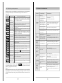
PJR2 Motor soft starter
Manufacturer: Shenzhen Powtran Technology Co., Ltd.
Technology Service Center of China
Powtran Building No75 baomin 2ed road xixiang street
baoan district shenzhen China
Tel: 86-755-29630738
Fax: 86-755-29666485
P.C.: 518101
Http: //www.powtran.com
E-mail:[email protected]
Technology Service Center of China
This manual is printed by ecological paper.
Powtran soft starter, control and protect your motor
Shenzhen Powtran Technology co., ltd.
Thank you for your purchasing our“PJR2 ”motor soft starter, which is used
to soft start and soft stop the three-phase asynchronous motor. Before use, please
read carefully and fully understand the instruction, so that you can operate it correctly.
1. Concernment before operating.............................................................................. 1
1-1 Inspection of incoming goods, 1-2 Product appearance......................................... 1
2. Installation and wiring....................................................................................... 2-8
2-1 Operating environment, 2-2 Installing method..................................................... 2
2-3 Wiring.............................................................................................................. 3
2-4 Wiring of main circuit and earth terminal............................................................. 4
2-5 Wiring diagram of main circuit of the soft starter.................................................. 5
Safety consideration
Please read this manual carefully to get the best performance of the soft starter. Please do not
change the set value if it is not necessary, as the change will affect its function and performance.
Please ask professional workers to modify the parameter of the soft starter if it is necessary.
Only professional workers are allowed to install PJR2.
Please make sure that the motor is equipped with the right PJR2 that with corresponding power,
and operate strictly according to the operating procedures that stipulated in user’s manual.
Do not connect the output terminal of soft starter with the capacitor, otherwise the soft starter
will be damaged.
After the PJR2 is installed, please wrap the copper wire terminal that on the input and output
terminal by insulating tape.
When it is remote control, please lock the key control.
Please make sure that the enclosure of soft starter is firmly earthed.
When maintain the equipment, please cut off the lead-in power supply first.
2-6 Wiring of control terminals................................................................................ 6
2-7 Layout diagram of control terminals................................................................... 7
2-8 Diagram of primary and secondary wiring........................................................... 8
3. Operation.............................................................................................................. 9
3-1 Inspection and preparation before operating, 3-2 Operation method....................... 9
4. Keyboard panel................................................................................................... 10
5. Basic functions.................................................................................................... 11
6. Instruction for function selection........................................................................ 12
6-1 Display mode.................................................................................................. 12
6-2 Control mode.................................................................................................. 12
6-3 Operating time of output relay.......................................................................... 12
6-4 Set the automatic restart function...................................................................... 12
7. Operating procedures.......................................................................................... 13
8. Help information................................................................................................. 14
9. Protection function......................................................................................... 14-16
9-1 Instruction of protection function..................................................................... 14
9-2 Setting of protection function........................................................................... 15
9-3 Protective tripping curve.................................................................................. 16
10. Protection performance..................................................................................... 17
11. Fault diagnosis................................................................................................... 18
12. Starting mode............................................................................................... 19-21
12-1 Current-limit starting mode, 12-2 Voltage ramp starting mode.......................... 19
Although this manual is compiled carefully, but we cannot guarantee that it is
absolutely correct. The technology and operating method of the products in this manual may be modified at any moment, so we cannot take it as a standard when sign
a contract.
12-3 Kick start, 12-4 Current ramp starting mode.................................................... 20
12-5 Voltage and current-limit double closed loop starting, 12-6 Soft stop, 12-7 Free stop.. 21
13. Outline size................................................................................................... 22-23
14. Application range............................................................................................... 24
15. RS485 communication........................................................................................ 24
16. Optional table of peripheral equipments............................................................. 25
17. Appendix............................................................................................................ 26
2-1 Operating environment
1-1 Inspection of incoming goods
After receiving the goods, please open the box to check the following items
to see if there is any problem on the products, if there is, or it is not your ordered
specification, please contact with the agent or the Powtran office nearby.
Table 2-1-1 indicates the requirements for operating environment
Table 2-1-1
PJR2 develops the electronic soft start-soft stop device
and has passed the performance test, complies with national standard: (GB14048.6-98)
Standard:
① To check the specification that on the nameplate of soft starter.
Nameplate
V
380-15%
Frequency
Hz
50
415+10%
440-15%
500+10%
Squirrel cage type three-phase asynchronous motor
T Y PE :
PJR2 017
Suitable motor
S O U R C E:
3φ 380V 50Hz
Starting frequency
Please do not exceed 20 times per hour.
O U TP UT:
17KW 35A
Degree of protection
Ip40 (Negotiable)
Resistance to im pact
15g 11ms
Shock resistant capability
Altitude below 3000m, the vibratory force device below 0.5G.
Z 0906S 00001
P OW T R AN T E C H N OL O G Y C O ., L T D
http://www.powtran.com
Model of soft
starter
Three-phase supply voltage (U)
MADE IN SHENZHEN CHINA
P JR 2 01 7 - 3
Rated voltage: 3
Ambient
temperature
380V
Working temperature
Standard motor capacity: 017
17KW
Ambient hum idity
055
55KW
Max working height
Serial No.
AC soft starter
Enterprise code of Powtran company
② Check the appearance to see if there is any dam age that caused by transportation, such as the
outside cover and machine case. Also inspect the parts to see if there is any dam age or loose phenomenon.
③ Besides the soft starter, there is a copy of operating manual.
④ When carry the soft starter, please carry the machine body but not control box of circuit board,
otherwise, there may be falling injury or bodily injury.
1-2 Product appearance
Coil in terminal of power
supply
(1 L1、3 L2、5 L3)
℃
Storage temperature
0 +40 no capacity-fall (+40~60℃, rise every 1 ℃, the
current will step down 1.2% ) 25 +70
95% no condensation or drip
No capacity-fall when lo wer than 100 0m (when higher than
1000m, add every 10 0m, the current will step d own 0 .5%)
M
Cooling system
Cooled by natural wind.
Max operating angle relative
to the vertical installing position
No requirement.
2-2 Installing method
① The soft sta rter shou ld be installed vertically, ne ver install it in inversion, gradie nt or level.
Make u se of screw to install it in a firm stru cture.
② When the soft starter runs, it will produce heat, in order to get enough cooling air, please
remain a certain space according to the diagram 2-2-1 during design. The heat produced will
emanate upwards, so please do not install the soft starter under the equipments that are not
thermal-resistant.
M achine base
Exhaust port
1 00
Control box of circuit board
1/L1
3/ L2
5/L 3
Keyboard panel
SJR 2 -3 7K W
50
Nameplate
50
Communication interface
R EA DY
P AS S
P ER RO R
准 备
运行
故 障
50
A
%
S
起动
RUN
设置
SET
确认
Y ES
停止
STOP
Term inal of control circuit
2/T1
Connect with the m otor
Connect with bypass contactor
(2 T1、4 T2、6 T3)
(A 2、B 2、C2)
-1-
A2
4/T 2
B2
6/T3
C2
1 00
图2-2- 1
-2-
Admitting
port
2-4 Wiring of main circuit and earth terminal
2-3 Wiring
Please pay attention to the following points when wiring. Refer to diagram 2-3-1
for basic wiring
①The power supply must be connected with terminals 1L1, 3L2 and 5L3 of m ain circuit, no phase
requirement. If there is any wrong connection, it will damage the soft starter.
②The ground term inals must be earthed finely, so that it can avoid electric shock or fire accident,
and it can reduce the noise.
③The two term inals of lead should be com pressed joint to assure high reliability in connection.
Diagram 2-3-1
Terminal name
1L1, 3L2, 5L3
Power supply input of main circuit
Connect with 3-phase power supply
2T1, 4T2, 6T3
Output connection of soft starter
Connect with 3-phase motor
Bypass connection
Connect with bypass electromagnetic contactor
Grounding terminal of soft
starter
The grounding terminal of the case
of soft starter should be earthed firmly
A2, B2, C2
Description
Main circuit
Equipped with bypass electromagnetic contactor
1 (K M) 2
Equipped with
circuit breaker
3
4
5
6
(1) Power supply input terminals of the main circuit (1L1, 3L2, 5L3)
① Power supply terminals 1L 1, 3L2 and 5L3 of m ain circuit connect with 3-phase power supply
through protective circuit breaker or leakage circuit breaker. It is not necessary to consider the
connecting phase sequence.
② Please do not adopt the ON/OF F control method (power supply of m ain circuit) to start or stop
the soft starter, you should electrify the soft starter first, and then make use of the control terminal
that on the soft starter or the RUN and S TOP keys to run or stop the machine.
③ Please do not connect with single-phase power supply.
(M C C B)
Or
Leakage
circuit breaker
380V
50/60HZ
Terminal mark
G
Diagram of
basic wiring
Power
supply
3-phase
Table 2-4-1 Function of main circuit and earth terminal
L1
A2
(E L C B)
2T1
1 L1
(2) Output terminals of soft starter (2T1, 4T2, 6T3)
B2
L2
3 L2
4T2
L3
5 L3
6T3
C2
G
FU
+ D C 12 V
M
① Connect the output term inals of the soft starter with 3-phase motor in correct phase sequence.
If the rotation direction of the motor is wrong, you can exchange the connection of any two phases of 2T1, 4T2 and 6T3.
② The output side of the soft starter can not be connected with capacitor and surge absorber.
③ When the wire between soft starter and motor is very long, the distributed capacitance am ong
the wire will produce high frequency current, it m ay cause phenom enon like over current and
trip, more leakage current, low accuracy of current display, etc. Therefore, we suggest that the
wire for motor connection should be less than 50m .
(3) Bypass connection (A2, B2, C2)
N
/
L1
Full voltage
output
A1
A2
Time delay
output
(Programmable)
01
07
Instantaneous stop
08
Stop
09
Start
10
Common port
Ue=
100%
02
03
K2
04
05
Fault output
K3
K1
06
(4) Grounding terminal of soft starter (
10
11
12
Control circuit
① The bypass connection terminals A2, B2 and C2 must be connect with the electrom agnetic bypass contactor, otherwise, the soft starter w ould be burne d. After the soft star ter is s tarted, the
power device of major loop (silicon controlled rectifier) exits, m eanwhile, the bypass electromagnetic contactor works, and the motor runs norm ally, pay attention to the phases, they cannot be
wrong connected.
Analog output
(DC 0-20mA)
G)
G of the soft
① In order to reduce noise and for safety consideration, the grounding term inal
starter must be firm ly earthed. In order to avoid electric shock and fire accident, the metal enclosure and frame of the electric equipm ent should comply with the national electric requirem ents.
■ Confirm that the input phase number and rated input voltage of the soft starter should be accord
with the phase number and voltage value of the AC power supply.
■ The AC power supply can not connect with the output terminals (2T1, 4T2, 6T3, A2, B2, C2)
■ The bypass electromagnetic contactor must be connected, and the phase sequence can be wrong
connected.
Otherwise, there may be accidents happen.
RS485 communication
-3-
-4-
2-5 Wiring diagram of main circuit of the Powtran PJR2 soft starter
3-phase power supply
Please refer to the table 2-6-1 for the function of control terminals. According to different
function setting, the function and connection of the control terminals will be different.
Table 2-6-1
50/ 60HZ
380V
L 1 L 2 L3
Classi- Terminal
fication mark
Equipped with
circuit breaker
(M C C B)
Or
(E L C B)
Leakage
circuit breaker
ON
OF F
2-6 Wiring of control terminals
01, 02
3
5
Motor soft
starter
(P JR2)
Equipped with
bypass electrom agnetic contactor
(KM)
W he n t he soft sta rt is fin ished st ar tin g, 01 a nd 0 2 clo se d
a nd c o ntr ol the b ypa ss e le c trom ag n et ic con ta ct or.
FU
01
L1
4
A1
A2
N / L3
03, 04
Operation
output
(Time delay)
03 and 04 are programmable relay output, the delay
time is set by code F4. Output function time is set by
code FJ, as NO, close when the output is effective.
(Contact rating AC 250V/3A ).
05, 06
Fault
output
05 and 06 are programmable fault relay output, they
will close when there is fault or it is power cut, and
they will open when it is power on.
(Contact rating AC 250V/3A).
07
Instantaneous
stop input
08
Soft
stop input
09
10
2
Bypass
output
Function description
02
1 L1 3 L2 5 L3
1
Terminal
name
Starting
input
Common
terminal
6
11, 12
Analog
output
C2
When 07 and 10 are open, the motor will stop working immediately (or joining up in series with NC of other protectors).
When 08 and 10 open, the motor will speed down and
soft stop. (Or free stop)
When 09 and 10 close, the motor will start to run.
The common terminal for contact to input signal.
11 and 12 is analog output for D C 0~20mA, it is used
to monitor the running current of motor, w hen it is full
range 20mA, it is 4 times of nominal rated current, it
can be connected with 0~20mA ammeter for monitoring
signal outside, its max resistance of output load is 300Ω.
B2
Communication
A2
2 T1 4 T2 6 T3
M
3-phase asynchronous motor
-5-
DB
RS485 communication
Input/output
The input/output signal terminal of RS485 communication, can be used to connect several soft starters.
(1) Contact input terminal
① When use external terminals to control soft starter to start or stop, please set the FD into external control is effective.
② If need r emote control, we sugges t using (two wires) control mode, please refer to 2-9 in Page 8
(two wires control mode).
③ Usually, the contact signal input terminal and common terminal will do close/open ( ON/OFF )
actions, the soft starter, motor and conductor arrangement will pr oduce interf erence, therefore,
please use shorter wire (shorter than 20m), and use shielding conductor for cable.
④ The conductor arran gem ent of control te rminal s hould be far awa y fro m the w iring of main
circuit. Otherwise, there may be error operation caused by interference.
-6-
2-7 Layout diagram of control terminals
2-8 Diagram of primary and secondary wiring of Powtran PJR2
(1) Terminals of main circuit
PJR2-90KW~500KW
PJR2-5.5KW~75KW
1/ L1
3 /L 2
1 / L1
5/ L 3
3 /L 2
5/L3
L1
L2
L3
1
3
5
N/ L1
A1
Circuit
breaker
KM
(QF)
2
4
FU
1
3
5
2
4
6
07
A2
B2
4 /T2
C2
B2
04
05
Running
output
06
B2
07
Instantaneous Start
stop
Soft
Common
stop
circuit
terminal
Instanta neous
Stop
stop
6 /T 3
It is forbidden
to input power
supply to 07-12
terminals
Control mode of relay
Analog
output
07
PJR2
07
08
09
Start
10
Common terminal
08
Stop
09
Start
10
Instantaneous stop
10
11
G
12
C omm on
Sta rt
terminal
K
10
Remote control mode
K
07
Stop
Instantaneous stop
09
Stop
10
2-9 Wiring diagram of relay and remote control
Two-wire control mode
Instantaneous stop
08
09
(DC0-20mA)
C2
07 08 09 10 10 11 12
Three-wires control mode
PJ R 2
08
C2
- A +
4 /T 2
Fault
output
(3) Terminals wiring of control
06
M
Bypass
output
03
05
6/T3
(2)Terminals of control circuit
02
04
Analog output
A2
6/T3
2 /T 1
01
03
G
G
2 /T1
4/ T 2
02
Fault
output
2 T1 4 T2 6 T3
A2
2 /T1
Time
delay
output
Full
voltage
output
01
1 L1 3 L2 5 L3
(KM)
A2
6
Start
08
KA
09
Common terminal
10
10
When K closes, it will start running,
when it open, it will stop running
-7-
Stop
KA
Start
Common terminal
Common terminal
10
Wire for control terminal0.75~1. 25mm2
K
10
KS
KA
10
Instantaneous stop
L
KA
KA
N
L
N
K is the N C point for other protectors (such as thermal protector), it is short-connection when leave the factory.
-8-
3-1 Inspection and preparation before operating
Before operating, please check the following points.
①Check if the wiring is right (especially the output terminals can not connect with power supply),
if the bypass contactor is firmly connected, and if the grounding terminal is earthed in fine condition.
②Please confirm that there is not short-circuit or shortened to earth phenom enon among term inals and naked electriferous parts.
or readiness
③After the power supply is turn on, the keyboard will display
and meanwhile, the ready indication lamp brightens.
4-1 Appearance of the keyboard
The keyboard has plenty of operating functions, such as functional data of confirmation and
changing for keyboard running and stopping, and various status confirmation, etc.
Indication lamp
of preparation
Colon
Indication lamp
of bypass running
READY
PASS
PERROR
Ready
Running
Fault
See diagram 3-1-1.
Fault indication lamp
Current
A
Percent
%
Second
S
Function code
Data code
起动
RUN
Up and down keys
Setting key
设置
SET
确认
YES
停止
STOP
Starting key
Stop key
Confirmation key
Diagram 3-1-1
Table 4-1-1 Functions of the operating keys
3-2 Operation method
Key name
Choose the m ost suitable operation m ethod according to the application requirements.
■ After confirm that there is no abnormal phenomenon, then you can trial run the machine. When
the product leaves the factory, it is set into keyboard operation mode.
■ Press F P to set the rated power current on the nam eplate of m otor.
起动
停止
■ Press “ RU N ” key to start the machine and“ S TO P ” key to stop it.
■ To see if the rotation direction of m otor accord with the requirements.
■ If the m otor starting action is not satisfactory, you can adjust the set basic function in P age11.
■ If the starting torque of the m otor is not enough, you can improve it through changing the starting voltage F0 (this way is effective when it is voltage mode) or cut-off current F6 (this way is
effective when it is current m ode).
■ To see if the motor rotates stably (No whistler sound and vibration).
If there isn't any abnormal phenomenon, then you can put it into formal operation.
Notice:
1.If the running of soft star ter and motor is abnor mal, or it displays fault code
,
please stop the machine imm ediately, and find out the cause according to“fault diagnosis”in
P 18.
2.When the site temperature is lower than 10C, please electrified and preheat for more than 30
m inutes and then start the machine.
-9-
Main functions
Starting key
起动
R UN
When display
Stop key
停止
ST OP
1. When it is normal running, it displays
(current value) and the bypass indication
lamp lightens, press this key can stop the machine. When the machine is fully stopped, it will
display
. 2. This key has reset function.
Setting key
设置
S ET
It displays
press this key and enter into the menu setting, when it displays
press it again.The colon flashes, at this moment, you can press“ Up” and“ DOWN” keys
to modify the parameter.
, press this key, it starts, and meanwhile displays starting state
1. When finishing the modifying work, press this key to keep the parameter, display
Confirmation key
确认
YE S
,
and give
sounds for two times, it means the data has been stored, press this key again or the stop key to exit.
2. Press this key and it displays the input supply voltage
3. Press this key
Up and
down
keys
.
确认
YES
, refer to table 8-1 in Page14 for details
and power on at the same time to reset the parameter back to the factory value.
1. Enter into the menu setting, press this key to modify the parameter, (when the colon doesn't
flash
, press the key to modify the function code. When the colon flashes
, press the key to modify the data code).
2. During running, press this key to observe the current A, power P and overload thermal equilibrium.
■ When
■ When
the data is larger than 999, the last radix point will be brighten, it means add 0 to mantissa.
press a key, there has sound given from the inner soft starter, if no, it means it is inefficient
to press this key.
■ The keyboard can be taken off, (when operate outside the cabinet) the length of the lead should be
less than 3m.
-10-
5-1 Function of code setting
Function code Name of function
Setting range
6-1 Code F8 is used to choose input mode and display mode
Factory value
Description
Effective under voltage ramp mode; when FB is set at 1,
it is modifiable, and set at 0, the starting voltage is 40%
Starting voltage
3 0-70%
Time of soft start
2 -60S
Effective under voltage ramp mode; when code FB
is set 1, the modification is effective
Time of soft stop
0 -60S
When it is set at 0, it is free stop, N-in-one set at 0
The set value of code F8
0
1
Input mode of F6 and F7
Current value
Display mode
Current value
2
3
Percent
Current value
Percent
Current value
Percent
Percent
■When code F6 and F7 input by percent, it indicates the percent of current value of the motor set by code FP.
6-2 Code FD is used to choose control mode of the soft starter
Time delay
starting
0-9 99S
Press starting key (set the time), time delay starting
by count down, set at 0, it will start immediately
Time delay
programming
0-9 99S
Output (03 and 04 terminals) of the relay, set at 0,
it will close immediately
Time delay
interval
0-9 99S
Time delay when release from overheat, the
indication lamp flashes during the tim e delay
Terminal control
Communication
Current limiting
when starting
50 -500%
Effective under curre nt limiting mode; when c ode
FB is se t at 0, the modification is effective, and set
at 1, the max current limiting value 400%
Max working
current
50 -200%
The input mode of parameter F6 and F7 is
determined by F8
Display mode of
the keyboard
Under-voltage
protection
Over voltage
protection
00-03
Refer to 6-1 in Page 12 for details
6 0-90%
Protect when it is lower than the set value
10 0-130%
Protect when it is higher than the ser value
Starting mode
00-05
00 current-limit; 01 voltage; 02 kick +current-limit;
03 kick +voltage; 04 current ramp; 05 double closed loop
Allowed output
protection
00-04
00 primary; 01 light load; 02 standard;
03 heavy load; 04 senior
Operating control
mode
00-07
When set at 0, it is keyboard operation,
refer to 6-2 in Page 12 fore details
Allowed restart
00-09
0: forbidden; 01-09: tim es of automatic restart
Allowed parameter
modify
00-01
00: not allowed to modify the parameter;
01: allowed to modify the parameter
Communication
address
00-64
Used for multi soft starters and upper machine for
multi-machine comm unication
Programming
output
00-07
Output setting (03 and 04 terminals) of relay,
refer to 6-3 in Page 12
Current limiting
when soft stop
Motor power
0-1
Refer to description in P21
5 -500K W
This soft starter serves for the motors below 18.5KW
Remark: 1. The m ax working current whose code is F7 means the max current for m otor's continuous operation on the basis of FP setting value.
2. If you do not pres s the operating keys when under the setting state, then it will exit
the setting state autom atically.
3. It is unable to set any parameter during soft start and soft stop, and you can set under
any other state.
-11-
0
Value of FD
1
2
3
4
5
6
7
Keyboard control
■ √ means can be chosen, and - means can not. If you want no unexpected stop after starting or no unexpected starting during maintenance, then you can set the FD at 7, and it will forbid any starting or stop operation.
■ When it is allowed external control, please connect with a NC button switch or short circuit between the
external control terminals 08 and 10, so that when it is open circuit, it can not start the motor.
6-3 FJ is used to set the operating time of output relay
0
Value of FJ
Operating time
of output relay
1
When send When
the starting starting
order
2
3
When
bypass
running
When
stop
4
5
6
When
When
When
finished instantaneous there
stopping stop
is fault
7
When the
auto restart
is finished
■ When the F4 is not 0, then take the above time as starting point and begins time delay according to set
time of F4. When time delay finishes, it acts, when F4 is 0, it will act immediately.
■ The output reset time (namely contact break) that is after F4 set time finishing delay, then retain 1s; if
start motor again, it breaks off last programming automatically, while, starting the cause. It can program
the relay output function flexibly, shorten the external control logic circuit efficiently.
6-4 Start functional setting automatically
■ FE is not 0, please permit to restart function automatically. This function is only for external control
two-wire mode, it is not controlled by FD. It is set at closing and starting according to the connection of
two- wire mode.
■ It delays for 60s when power is on, then it will start again automatically.
■ F5 set time is more than 60s, pleas delay though pressing F5 set time. The indication lamp flashes at
delaying state.
■ It can start for“n ”times, besides starting when power is on and restarting after occurring the fault,
“n” is the FE set value.
■ Automatic restarting doesn't effect until it is started, it still effects if switch on every time.
This soft starter possesses the loss-voltage protection function, it says that the power is
off but power is on later, wherever the external terminal is, it can't start automatically, in
order to prevent the injuring accident. When automatic restarting is permitted, the power
failure protection is unavailable.
-12-
7-1 Amend the setting parameter
Press“ SET” key
Power on
8-1 Help information
Press“ UP” and“ DOWN” key
Press SET key
Display
Description
Three-digit voltmeter, which is used for monitoring three-phase AC supply voltage
Enter the code selection
Choose code function
Confirm amending code
The last fault is prompted by
of phase
Press “ UP” And“ DOWN” key
Press YES key
Amend the setting range
Retain the amending data
(Exit)
Display
,this means that the input is loss
It m eans no fault
Take the example of amending (Operating control code, external terminal control, FD is set for 2).
Code Operate
The spec of this soft starter is 55KW/380V
It can enter the help information under no soft start/soft stop, please press
press
or
key to refer the prompt information.
确认
YES
key, then
Description
9-1 Instruction of protection function
1
Power on
2
Press SET
key
3
Press Up
key for
13 times
4
Press SET
key
5
6
Press UP
key for
2 tim es
Press
“YES ”
key
00000or
设置
SET
设置
SET
ready state
PJR2 series has perfect protection function, in order to safe to use. Dur ing using, please set
the protection grade and protection param eter properly according to different situations.
Enter the state of function code selection
when the temperature falls at 55 ℃ (min), the over-heat protection is rem oved.
Enter the state of FD function code selection
(Operate control mode)
■ The lag tim e of input open-phase protection: Less than 3s.
■ The lag tim e of output open-phase protection: Less than 3s.
■ The lag tim e of three-phas e unbalance protection: L ess than 3s. Base on the declination of
Flash the colon, it means that the setting range
may be amended.
each-phase current more than 50%, when the load current is lower than 30% of nominal rated
value of soft starter, the reference declination decided is increased.
■ Tim e of over-current protection at starting: The tim e of protection that when the duration is
more than 5 tim es of F7 max working current is shown in P 15:19-2-1table.
■ Tim e of over-load protection at running: B asing on the F7 m ax working cur rent, it runs the
inverse tim e lag protection, the curve of protection is shown in P16:9-3-1.
■ Lag tim e of over-low protection of supply voltage: When the supply voltage is lower than 40%
of the limited value, the pr otection action tim e is less than 0.5s , otherwise, this protection
action would be less than 3s when it is less than this value.
■ Lag tim e of over-high protection of supply voltage: When the s upply voltage is higher than
130%, the protection tim e is less than 0.5s, otherwise, it is higher than this value, the protection tim e is less than 3s.
■ Lag tim e of load short-circuit protection: Less than 0.1s, the current is m ore than 10 tim es of
nom inal rated current of soft starter.
■ Above param eter that is from detecting the effective signal to send the release protection order,
the parameter is only for reference.
It says that the external terminal control
确认
YES
■ Over-heat protection: When the temperature rises at 80℃±5 ℃, it causes the protection action,
The amending data has been retained. (Exit)
When operate the key, the inner buzzer in the soft starter sends the sound for prompting.
In case that the protection function of soft starter doesn't meet the user's requirement, please add
special protection equipm ent.
-13-
-14-
9-2 Setting of protection function
9-3 Protective tripping curve.
Cater for different occasions, PJR2 series soft s tarter has set f ive pr otection grades, they are
0 junior, 1 light load, 2 standard, 3 heavy load, 4 senior, all of them are set by FC.
■ The junior protection has prohibited the external instantaneous stop function, while, only retaining over-heat protection, short-circuit protection and input open-phase pr otection at starting, it is used for the occasion that doesn't need any condition to start the emergent starting.
■ Light load protection, standard protection and heavy load protection posses com plete protection function, they are distinguished by the curve of overload heat protection tim e of motor.
The parameter of heat protection time of motor is shown in the table 9-2-1 and diagram 9-3-1.
■ The protection standard at starting for senior protection is s tricter, other protection function
param eter is the same with that of standard protection.
Different protection grade and heat-protection time set by FC is shown in table 9-2-1
Table 9-2-1
FC set
0 Junior
1 Light load
2 Standard 3 Heavy load
4 Senior
Operating
overload
Protection grade
No
2 grade
10 grade
20grade
10 grade
Starting current
Protection time
No
3s
15s
30s
15s
The curve for release protection of motor as per IEC60947-4-2 standard
Diagram 9-3-1
t(s)
1000 0
1000
Description
As per
IEC60947-4-2
standard
Calculated according
to the starting current
over 5 times set by F7
Current
Releasing tim es
3 4 5 3 4 5 3 4 5 3 4 5 3 4 5
The value in
time of (I/Ie)
tableis the
running
topical value.
overload Releasing
time
4.5 2.3 1.5 23 12 7.5 46 23 15 4.5 2.3 1.5 23 12 7.5
(s)
100
10
30
20
■ Set the FP, otherwise according to the rated current value on the motor nameplate, when
F6, F7 input mode are the percentage mode (Set by F8), the starting current and protecting
current would have the large difference.
■The motor current set by FP can't be lower than 20% of nominal current of soft starter, when
the motor current set by FP is smaller, the error of sensitivity of protection release is increased.
10
1
2 Id/I n
0.5
1 .12 1 .5 0 2 .0 0 2.5 0 3.0 0 3 .5 0 4 .00 4 .50 5 .0 0 5 .5 0 6 .0 0 6 .5 0 7.0 0 7.5 0
Curve for thermal protection of motor (State)
-15-
-16-
10-1 The list for protection operation
11-1 Problem and countermeasure
When the soft starter occurs abnormity, the protection function runs, it trips immediately,
LED displays alarming name and concerned content, please refer to table 10-1-1.
Table 10-1-1
Panel display
Alarming nam e
The fault has
been removed
External instantaneous-stop
terminal opens circuit
Check if 07 and 10 terminals are connected, and the NC contact are
connected with other protective equipment or not.
Over long starting
Content checked
Countermeasure
The wiring
Weather the power wire
is connected to input the
terminal or not.
(1L1, 3L2, 5L3)
Please give the correct wiring
Switch on power
Cut off the power, then switch on
Weather bypass contactor
w orks or not, and 01, 02
terminal has no signal or not.
Check the connection situation of bypass contactor.
Check the connection situation of coil of bypass
contactor.
Weather the keyboard is
abnormal to display or not.
Please read P17 “Protection operation list ”
Weather the motor is locked
or not, (Weather the load is
too heavy or not).
Clear away the locking of motor (Reduce the load)
The
keyboard
can't start
Weather the keyboard has
displayed or not.
Weather 07, 10 terminals
open circuit or not, FD
setting is correct or not.
No: Weather the po wer opens phase or not, check
the inlet power.
Yes: 10 and 07, 08 open circuit, check external connection of terminal, please set the FD code correctly.
External
control
can't start
Weather FD is set at external controlling or not.
Terminal 10 and 07, 08 opens circuit, check the external connection of terminal, please set the FD code
correctly, check if it is in the external control poison
or not
Although
the m otor
rotates, the
speed is not
changed.
Weather the load is too
heavy or not.
Please reduce the load
Add the initial voltage or starting current
Operation content and treatment
The faults like over-voltage, under-voltage, or overheat, ins tantaneous
stop terminal opening circuit has b een removed, then, turn on the lamp,
press“YES”key to start the motor.
Soft starter is over heat
Abnormity
The motor
can't run
The starting is too frequently, or the pow er of motor isn't fit ted with
that of soft starter.
The starting parameter is set improperly, or the load is too heavy, the
power capacity is not enough.
Input open-phase
Check the power for 3-phase, make sure that by-pass contactor isn't
clamped in the closing position, the controllable silicon isn't short
circuit, KG wire is connected well.
Output open-phase
Examine output circuit and connecting wire of motor, make sure that
by-pass contactor isn't clamped in the closing position, the controllable
silicon isn't short circuit, KG wire is connected well.
Three-phase unbalance
Check if input three-phase power and load motor are normal or not.
Start over-current
Check if the load is too heavy or not, or the power of motor isn't fitted
with that of soft starter.
Run over-load protection
Check if the load is too heavy or not, or the F7 parameter is set wrong.
Too low supply voltage
Check input supply voltage, or F9 parameter is set wrong.
Too high supply voltage
Check input supply voltage, or FA parameter is set wrong.
The set parameter is error
Amend the setting or press
Load short-circuit
Check the load or motor, and the controllable silicon is short circuit
or load is too large.
Auto matic restart,
th e con nection is
error
Check the external contro l starting and stop pin g terminal is conn ected
with 2 -w ire controlling mode.
The starting
time is too
long.
The load is too heavy, the
code hasn't been set, weather the spec of motor is
correct or not.
Please reduce the load
Please set F0 (Initial voltage), F6 (Starting current),
F1(Starting time)
Please check the specification and nameplate
The connection of
external stopping
terminal is error
When the external control mode is permitted, the external control
s topping ter minal is in t he ope n-circ uit state , so it can't star t the
motor.
The starting
time is short
The load is light
The starting time is too
short
When the load is light, the starting time is often less
than setting value, the starting is normal, set the staring time of F1( the current mode is unavailable).
It stops
suddenly
during
running.
Check the external input
terminal
Check co nnection of 07, 1 0 terminals fails o r not.
If th e external protector is equip ped w ith, please
check NC contact op erates or not
Check the conn ection of external stop button fails
or n ot.
确认
YE S
key to start and recover the factory value.
Some faults is related, for example, report that
soft starter is over heat, starting
over current or load short-circuit, therefore, when check the fault, please consider comprehensively, to judge the faults accurately.
Notice:
When soft starter starts motor successfully, the indication lamp for running in the middle
of panel lightens, it says that the it runs at the bypass, if the bypass contactor can't absorb,
it will cause the motor stops running, thus, you shall check the bypass contactor and connection.
-17-
-18-
12-1Current-limit starting mode, 12-2 Voltage ramp starting mode
① It is the current starting mode when FB is set for 0 (0 limited current). The current various waveform of m otor at limited curr ent starting m ode is s hown in the diagram 12-1-1. Thereinto,
I1 is the s tar ting current-lim it requir ed, when the motor star ts, the output voltag e incr eases
rapidly, till the current of motor reaches the current-limit I1 required, and the current of motor
shall be not more than this value, then the m otor speeds up step by step a s the rising of output
voltage, when the m otor is up to the rated rotary speed, the bypass contactor absorbs, the output current falls down rapidly to rated current of motor Ie or below, up to now, the starting has
been finished.
②W he n the load of motor is too light or the lim ite d current set is too high, it is normal that the
m ax current at starting is likely not to get the lim ited current set. Generally, the curr ent-lim it
starting is used for the occasion that requires the starting current strictly.
I
12-3 Kick start
① FB sets for 2 (Kick + limited current) or sets for 3 (Kick + voltage) star ting m ode, output variable waveform of kick starting mode is shown in diagram 12-3-1 and diagram 12-3-2. In som e
occasion with heavy load, if the motor can't be started due to mechanical s tatic f riction f orce,
this starting mode can be chosen. Before starting, please apply high fixed voltage to motor and
let it keep for limited time, in order to rotate the motor through overcoming the static friction
force, then, make it start according to limited current or voltage lamp mode.
② Before using this mode, please start this motor with non kick mode, if the motor can't rotate for
too large static friction force, then you can choose this mode; otherwise, please avoid this mode
to start for reducing the unnecessary large current impact.
C
C
U n1 0 0%
U n1 0 0%
U1
U1
I1
Diagram 12-1-1
Ie
0
0
T
T
1 0 0m s
0
T
10 0 m s
12-2 Ramp start of voltage
① It is the current starting mode when FB is set for 1 (1 limited current). The output voltage
various waveform at voltage ramp starting is shown in the diagram 12-2-1. Thereinto, U1
is the initial voltage at starting, when the motor starts, the current of motor can't be more
than 400% of rated value, the output voltage of soft starter reaches U1 rapidly, then, th e
output voltage rises generally according to the staring parameter, the motor speeds up stably as the voltage, when the voltage reaches rated voltage Ue, when the motor gets the
rated rotary speed, the bypass contactor absorbs, thus, the staring has been finished.
②The starting time t is the control parameter got according to standard lo ad under the standard experiment, PJR2 series soft starter takes this parameter as the reference, the motor
can speed up stably with the help of control output voltage to finish the starting, it doesn't
consider the motor rotation situation not due to mechanical control time. In term of this,
when the load is light, the starting time is often less than the one set, only it can start smoothly, it belongs to normal. Generally speaking, the ramp start mode of voltage is applicable for start stability that is required strictly but the start current.
Diagram 12-3-1
Diagram 12-3-2
12-4 Current ramp starting mode
① FB sets for 4 that is this starting m ode. Diagram 8-1-3 is the output current waveform of current ramp starting m ode. Thereinto, I1 is the limited value set by F6, T1 is the tim e set by F1.
② The current ramp starting mode has the strong acceleration ability, it is suitable for two-pole
m otor, also can shorten the starting tim e in the certain range.
I
I1
U
Diagram 12-4-1
Ue
Ie
Diagram 12-2-1
U1
0
0
t
-19-
T1
T
-20-
T
12-5 Voltage and current-limit double closed loop starting
① When FB is 5 (Double closed loop), it is the double closed starting mode. This mode adopts
voltage ramp and current-limit double closed loop to control, it is a comprehensive starting
mode that requires stable starting and strict current-limit, and it adopts the pre-calculating
method that evalu ates the working state of motor.
② The output volta ge waveform of this kind of starting mode will be different according to the
motor and loading condition.
13-1 PJR2 005 to PJR2 075
2X
57
1 /L1
3 /L2
7
128
5/L 3
P JR2-7 5KW
12-6 Soft stop
R EAD Y
PAS S
PER ROR
准备
运行
故障
A
%
PJR2 series soft starter has two stop modes that is soft stop mode and free stop mode.
① When F2 is not 0, it is soft stop mode. Refer to diagram 12-6-1 for output current waveform of
soft stop mod. TF is soft stop time set by F2. Under this stop mode, the power supply of motor
can be got through bypass contactor switching into thyristor output of soft starter, the output
voltage of the soft starter will be reduced gradually from full voltage, in this way, it reduces
the rotary speed gradually without causing the vibration till the motor stops. The output cutoff voltage of soft stop is equal to the starting voltage.
② Soft stop mode can reduce or eliminate the load surge like water pump. Under soft stop mode,
you can set soft stop current-limit value by FL to reduce the heavy current impact when reducing soft stop, this soft stop current-limit value is a percent that is calculated on the basis of
starting current-limit.
S
起动
RU N
设置
SET
2/ T1
A2
4/T 2
B2
确认
YES
6 /T3
停止
STOP
C2
4X
145
167
Face
Side
7
2X
6.5
Accessory
of base
Base
13-2 PJR2 090 to PJR2 200
V
260
210
Diagram 12-6-1
80
241
57
80
120
TF
PJR 2-37K W
12-7 Free stop
RE AD Y
P ASS
PER RO R
准备
运行
故障
A
%
S
① Set F2 at 0 (free stop), it is free stop mode.
Under this stop mode, as soon as the soft starter receiving the stop order, it will switch off the
bypass contactor immediately and forbid the voltage output from thyristor, and the motor will
stop gradually as the load inertia. When the wiring method of the soft starter is in n-in-one, then
you'd better set it into this mode to avoid loss-of phase fault report during output switching.
② Usually, you should choose the free stop mode if it is not necessary to choose the soft stop. Free
stop will prolong the service life of soft starter. The free stop mode completely forbids instantaneous output, it avoids instantaneous heavy current impact in special application condition.
起动
RUN
设置
SE T
确认
YES
停止
S TOP
Powtran PJR2 soft starter has six different starting modes, it is suitable for various complex motors and different bad conditions, and the users can choose according to their application ranges.
4X
58
9
120
-21-
-22-
13-1 PJR2 200 to PJR2 400(500)
14-1 Sort of application load
Powtran PJR2 soft starter can meet the requirement that drives heavy loads, the below table is only
for reference.
Applicab le loads
29 0
23 5
90
2 80
57
90
13 5
RE A DY
P A SS
P ER R OR
准备
运行
故障
起动
RU N
设置
S ET
确认
Y ES
停止
S TO P
62
4X
9
13 5
In case that the outline size is changed, please refer to the real object.
Vo ltage s tarting Current(Max curren tlimit starting
limit value)
40
4
2.5
Ball mill
20
6
60
4
3.5
Fan
26
4
30
4
3.5
Light load mo tor
16
2
30
4
3
P is ton ty pe
co m pr es so r
16
4
40
4
3
6
10
60
4
3.5
Agitator
16
2
50
4
3
Crusher
16
10
50
4
3.5
Spiral ty pe c om
pre ssor
Sp ir al t yp e b elt
c o n v ey e r
16
2
40
4
3
20
10
40
4
2
Conveyer belt
20
10
40
4
2.5
Heat pump
16
20
40
4
3
A
S
Initial voltage
(%)
20
E levat in g
m ac hi n er y
%
Stop ram p
time (s)
16
Centrifugal pump
PJR 2- 37 KW
Starting ramp
time (s)
15. RS485 communication
The Powtran PJR2 soft starter can be connected with personal computer and PLC through build-in
Rs485 standard interface., it can proceed serial communication.
We can use the host command to start/stop the soft starter, it also can monitor its running state and
modify its function data etc..
Please refer to the RS-485 operating manual about the detail communication content.
We can use RS 485 communication of soft starter through a computer to proceed remote control,
order input, running state control and input the function data of many soft starters in one time.
Main functions
Input the stop order
Monitor the running state
Real-time trace (Display the running information in a table)
Read and write in the function code in one time, and keep it in the document.
Please contact with us to negotiate the communication software.
-23-
-24-
16-1 Equipment fitted with PJR2 soft starter and the wire size
About warranty period and after-sale service
(Voltage: 380V)
Parameter of motor
Soft starter
Circuit breaker
Electromagnetic
contactor
Power Current
(KW)
(A)
Model & Spec
Model & Spec
Model & Spec
Cable/copper bar
Thank you for purchasing soft starter produced by Powtran company, this product is manufactured
under a perfect quality control system, but once there is any fault, please refer to the following points
for the warranty period and after-sale service.
Spec of copper core
1.Warranty period
( mm2)
The warranty period of the product is 12 months from purchasing or 20 months from production
date that on the nameplate, if exceed any one of this two period, we will determine that the product
is beyond the warranty period. However , if the fault is caused as follows, no matter if it is warranty
period, we will ask for the cost of repair.
1)Wrong operation, change this product by yourself or unreasonable maintenance, etc..
2)Operated beyond the standard specification.
3)After being purchased, the product is damaged due to falling down or transportation, etc..
4)Caused by earthquake, fire, wind accident, lighting strike, abnormal voltage, other Act of God
or quadratic damage, etc..
5.5
11
P JR 2 00 5
CM 1 -6 3/ 1 6
LC 1 D1 2
2. 5
7.5
15
PJR 2 00 7
CM 1 -6 3/ 2 0
LC 1 D1 8
4
11
21
PJ R 2 01 1
CM1 -63/ 32
LC 1 D2 5
6
15
28
P JR 2 01 5
CM 1 -6 3/ 4 0
LC 1 D3 2
10
18. 5
34
PJ R 2 01 8
CM 1 -6 3/ 5 0
LC 1 D3 8
10
22
42
P JR 2 00 5
CM 1 -6 3/ 6 3
LC 1 D5 0
16
30
54
PJR 2 0 3 0
CM 1 -1 00 / 80
LC 1 D6 5
25
37
68
PJR 2 03 7
CM 1 -1 00 / 100
LC 1 D8 0
35
45
80
P JR 2 04 5
CM 1 -1 60 / 125
LC 1 D1 1 5
35
55
98
P JR 2 05 5
CM 1 -1 60 / 160
LC 1 D1 1 5
35
75
12 8
P JR 2 07 5
CM 1 -2 25 / 180
LC 1 D1 5 0
50
90
16 0
PJR 2 0 9 0
CM 1 -2 25 / 225
LC 1 F1 8 0
30 X 3
1)When the operation state is not in right condition, please check it and fine the cause according
to the operating manual.
2)Please contact with the sales agency or after-sale service window, agency of our company in the
operating manual when the machine occurs faults.
3)Maintenance during warranty period: Faults caused by pr oduction pr oblem, we will offer the
maintenance, please correctly fill the War ranty f or Powtran softstarter in detail, otherwise, we
would ask for the cost of repair.
4)Maintenance beyond the warranty period: Offer basic maintenance only for maintaining the
function, and then ask for the cost repair for further maintenance according to customer's
requirement.
115
19 0
P JR 2 11 5
CM 1 -2 25 / 315
LC 1 F2 2 5
30 X 3
Warranty for soft starter of Powtran
132
23 6
P JR 2 13 2
CM 1 -4 00 / 315
LC 1 F2 6 5
30 X 3
Customer's name
160
29 0
PJR 2 1 6 0
CM 1 -4 00 / 350
LC 1 F3 2 0
30 X 5
Address
2.After-sale service
Tel
Chief name
Fax
200
36 7
PJR 2 2 0 0
CM 1 -4 00 / 500
LC 1 F4 0 0
30 X 5
250
43 0
PJR 2 2 5 0
CM 1 -6 30 / 630
LC 1 F5 0 0
40 X 5
Shop name
Purchasing date Date:
280
47 0
PJR 2 2 8 0
CM 1 -6 30 / 630
LC 1 F5 0 0
40 X 5
Address
320
54 7
PJR 2 3 2 0
CM 1 -6 30 / 700
LC 1 F6 3 0
40 X 5
When does the
Date:
fault show?
400
72 5
PJR 2 4 0 0
CM 1 -8 00 / 800
LC 1 F8 0 0
40 X 8
Above equipments fitted are only for reference.
PJR2-
Ex-store code
Model
- Fault state-
Application
When does
it show?
What does it display
when the fault shows
Run a ft er
re set ting
Control terminal
applied
Motor
During c ontinuous run ning
Switch on O the rs (
Alarm display (
Is power on ?
KW
During spe edi ng up
)
) Does the keyboard display (
Pole Model
During spe eding down
) Output voltage (Yes No )
Possible Impossible Reset method Keyboard panel Terminal Power supply Others (
01,02 03,0 4 0 5,0 6 07 08 09 10 11,1 2
Working time
-25-
KW
Yes No
Find the
frequency
Is there an y m ach ine
ab norma l arou nd it?
/
Yes
-26-
Others (
Installa tion
place
No
Last fault
Yes(Show
times) No
)
)