1
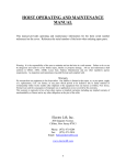
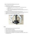
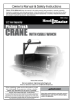
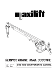
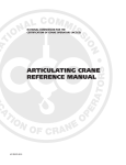
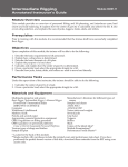
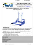
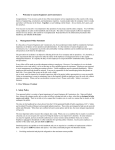
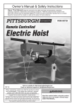
Table of Contents
SAFETY
Safety.......................................................... 3
Specifications.............................................. 4
Setup........................................................... 4
Operation..................................................... 5
Inspection.................................................... 8
Parts List and Diagram............................... 11
Warranty..................................................... 12
SETUP
WARNING SYMBOLS AND DEFINITIONS
This is the safety alert symbol. It is used to alert you to potential personal injury hazards.
Obey all safety messages that follow this symbol to avoid possible injury or death.
Indicates a hazardous situation which, if not avoided,
will result in death or serious injury.
Indicates a hazardous situation which, if not avoided,
could result in death or serious injury.
Indicates a hazardous situation which, if not avoided,
could result in minor or moderate injury.
OPERATION
Addresses practices not related to personal injury.
INSPECTION
Page 2
For technical questions, please call 1-800-444-3353.
Item 69854
69855
IMPORTANT SAFETY INFORMATION
Basic Safety Information
2. Do not operate while puller restricted from
forming a straight line with loading direction.
3. Do not operate puller with twisted, kinked, or
damaged wire rope.
Inspect wire rope carefully before every use.
4. Do not operate a damaged or malfunctioning
puller. Inspect puller carefully and
test operation before every use.
5. Do not use for vertical lifting.
Do not lift people or lift loads over people.
Falling loads can injure or kill people.
6. Do not operate puller with a lever extension.
7. Do not operate with rope not
centered in its groove.
8. Do not remove or cover warning labels and/
or tags. These carry important safety information.
If unreadable or missing, contact
Harbor Freight Tools for a replacement.
9. The warnings, precautions, and instructions
discussed in this instruction manual cannot
cover all possible conditions and situations
that may occur. It must be understood by the
operator that common sense and caution are
factors which cannot be built into this product,
but must be supplied by the operator.
SETUP
1. Do not pull more than rated load. Be aware of
dynamic loading! Sudden load movement may
briefly create excess load causing product failure.
SAFETY
TO PREVENT SERIOUS INJURY AND DEATH:
Setup Specific Safety Information
2. Install in location that allows the operator
to move and stay clear of the load.
3. Inspect the puller as explained in Frequent Inspection
on page 8 after setup but before use.
Inspection, Testing, and Maintenance Specific Safety Information
1. Perform a “Frequent Inspection”
at least monthly, see page 8.
3. More frequent inspections are needed
for pullers that are used heavily.
2. Perform a “Periodic (Thorough) Inspection”
at least yearly, see page 9.
4. Raise test loads only to the minimum extent needed
and stay well clear of load at all times during testing.
OPERATION
1. The supporting structure the puller is mounted
to must be designed to withstand the loads and
forces imposed by the puller for the rated load.
Operation Specific Safety Information
2. This product is not a toy.
Do not allow children to play with or near this item.
3. Use as intended only.
• Do not use to handle molten material.
• Do not use for aircraft purposes.
• Do not use to link towed vehicles.
INSPECTION
1. Wear ANSI-approved safety goggles,
ANSI‑approved hard hat, and
steel‑toed work boots during setup and use.
4. Keep hands clear of moving parts.
SAVE THESE INSTRUCTIONS.
Item 69854
69855
For technical questions, please call 1-800-444-3353.
Page 3
Specifications
Model
69854
SAFETY
Rated Capacity
4,000 lb.
Maximum Extension
6.75′
69855
8,000 lb. double line
4,000 lb. single line
6′ double line
10′ single line
Setup Instructions
Read the ENTIRE IMPORTANT SAFETY INFORMATION section at the beginning of this
manual including all text under subheadings therein before set up or use of this product.
SETUP
Note: For additional information regarding the parts listed in the following pages,
refer to Parts List and Diagram on page 11.
1. The supporting structure the puller is mounted to
(including trolley, monorail, or crane)
must be designed to withstand the loads and
forces imposed by the puller for the rated load.
2. Properly seat the anchor hook on the supporting
structure at its intended load bearing point
(see the left side diagram of Figure A).
Do not allow the hook hitch
to support any part of the load.
Do not apply the load to the point of the hook
(shown in Figure A on the right side diagram).
OPERATION
Figure A: Correct and incorrect
anchor hook attachment
INSPECTION
Page 4
For technical questions, please call 1-800-444-3353.
Item 69854
69855
Operation Instructions
SAFETY
Read the ENTIRE IMPORTANT SAFETY INFORMATION section at the beginning of this
manual including all text under subheadings therein before set up or use of this product.
TO PREVENT SERIOUS INJURY: Operation of a puller involves more than pulling the lever.
The use of pullers is subject to certain hazards that cannot be met by mechanical means,
but only by the exercise of intelligence, care, common sense, and experience in
anticipating the motions that will occur as a result of operating the controls.
Do not use this tool for vertical lifting.
Before Operating Puller
2.
4. Only a qualified technician should
perform maintenance to the puller.
5. Do not use the wire rope as a ground for welding.
Do not touch a welding electrode to the wire rope.
WARNING! TO PREVENT SERIOUS INJURY
FROM PULLER FAILURE:
Do not use damaged equipment.
If adjustments or repairs are necessary,
or any defects are known, have the
problem corrected before further use.
3. Do not operate a puller with an out-of-order sign.
6. Designate a work area that is clean and well‑lit.
The work area must not allow access by children
or pets to prevent distraction and injury.
SETUP
1. Familiarize yourself with all operating controls
of the puller and with the operation(s) to be
performed. Instructions include, the warnings
on the puller, and the safety and operating
instructions portion of this manual.
7. There must not be objects, such as utility lines,
nearby that will present a hazard while working.
8. Inspect the puller as explained in Frequent Inspection
on page 8 after setup but before use.
OPERATION
Operating Controls
Lever
Drive
Pawl
Anchor
Hook
Wire
Rope
Stop Pawl
Trigger
(hidden)
End Hook
(item 69855 only)
Guard
Pulley
Hook
Figure B
Item 69854
69855
For technical questions, please call 1-800-444-3353.
Page 5
INSPECTION
Ratchet
Pawl
Spring
Applying the Load
1. The 69855 puller is designed for
single or double line pulls.
9. Pull the wire rope out to reach the load.
SAFETY
a. A single line pull can reach twice as far and retract
twice as fast, but it has half the weight capacity.
b. To do a single line pull, unhook the
wire rope end hook and use it as the load hook.
c. For double line pulls, attach the end hook
to the puller’s frame as shown in Figure B,
and use the pulley hook as the load hook.
10. Release the Stop Pawl Trigger.
11. Do not wrap the puller wire rope around the load.
12. Attach the load to the load hook securely by
properly rated, suitable means, such as chains,
shackles, hooks, lifting slings, etc. Load must be
attached to prevent accidental disconnection.
6. Swing the Handle away from the
Anchor Hook to expose the Drive Pawl.
Ratchet
Drive Pawl
disengaged
engaged
SETUP
Figure E: Correct and incorrect
load hook attachment
Pawl
Spring
Figure C: Drive Pawl Operation
OPERATION
7. Slide the Pawl Spring up to the disengaged position.
The Drive Pawl will be held clear of the Ratchet.
Anchor Hook
Ratchet
13. Properly seat the sling or other device
in the base (bowl or saddle) of the hook
(see the left side diagram on Figure E). Do not
allow the hook hitch to support any part of the load.
14. Do not apply the load to the point of the hook
(shown in Figure E on the right side diagram).
15. Before moving the load, make sure wire rope is
not kinked or twisted or that multiple part wire
ropes are not twisted around each other.
16. Do not operate the puller unless wire rope is seated
properly on the drum, pulleys, or sprockets.
17. Do not pick up a load in excess of the rated
load appearing on the puller or load block,
except during properly authorized tests.
Do not use a puller overload limiting device to
measure the maximum load to be pulled.
Stop Pawl
Trigger
18. Give specific attention to load balancing and
hitching or slinging to prevent load slipping.
INSPECTION
Stop Pawl Trigger
Load/Pulley
Hook
Figure D: Releasing the Stop Pawl
8. Squeeze the Stop Pawl Trigger as shown above.
Page 6
For technical questions, please call 1-800-444-3353.
Item 69854
69855
1. Slide the Pawl Spring down to the engaged position,
as shown in Figure C. The Drive Pawl
will be pressed against the Ratchet.
2. Do not engage in any activity which will divert the
operator’s attention while operating the puller.
3. Respond to signals from a designated person only.
However, always obey a stop signal,
no matter who gives it.
7. Each time a load approaching rated capacity is
handled, check puller brake action by pulling the
load just clear of supports and continuing only after
verifying that the brake system is operating properly.
8. WARNING! Do not carry any
load over any person.
9. WARNING! Do not carry personnel
on the hook or the load.
4. Do not move a load with the puller until the operator
and all other personnel are clear of the load.
10. Pull the Handle toward the Anchor side
of the Puller. This will pull the Load.
5. Make sure the load and puller will clear all
obstacles before moving or rotating the load.
11. Swing the Handle back and forth until the load
has been pulled to the desired position.
SAFETY
Moving the Load
Parking the Load
2. Exercise care when removing a sling from
under a landed and blocked load.
3. Secure the load so it will not move before
releasing the tension on the wire rope.
4. To release the wire rope tension:
a. Swing the Handle away from the
Anchor Hook to expose the Drive Pawl.
b. Slide the Pawl Spring up to the
disengaged position. The Drive Pawl
will be held clear of the Ratchet.
c. Swing the handle to the Anchor Hook side and
force the spring loaded STOP PAWL pin down,
then slowly raise the handle. This action will allow
the wire rope drum to back off by one cam step.
d. Repeat this action, as needed, until the
tension on the wire rope eases.
e. Pull on the STOP PAWL TRIGGER to release it
from the cam and gently pull back on the tool to
get wire rope slack and free it from the load.
5. To prevent entangling of the wire rope onto the
drum, with the Load Hook still attached to the
load, push the spring into its “Down” position.
Hold the Anchor hook in one hand. While gently
pulling against the load, swing the Handle
back and forth to rewind the wire rope.
INSPECTION
CAUTION: Do not rewind the wire rope to its end.
OPERATION
1. Do not leave a supported load unattended
unless specific precautions have been
instituted and are in place.
SETUP
6. Do not move a load more than a few inches until
it is well balanced in the sling or pulling device.
Item 69854
69855
For technical questions, please call 1-800-444-3353.
Page 7
Inspection, Testing, and Maintenance
Procedures not specifically explained in this manual must
be performed only by a qualified technician.
SAFETY
TO PREVENT SERIOUS INJURY:
Remove any load before performing any inspection, maintenance, or cleaning procedures.
TO PREVENT SERIOUS INJURY FROM TOOL FAILURE:
Do not use damaged equipment. If abnormal noise or vibration occurs,
have the problem corrected before further use.
Frequent Inspection
SETUP
Perform the procedures in this section BEFORE
INITIAL USE and AT LEAST MONTHLY. Inspection
is needed more often for heavily used pullers.
1. Check operating mechanisms for proper operation,
proper adjustment, and unusual sounds
such as, but not limited to, binding noise
of the wire rope and bearing squeal.
2. Frequent Braking System Inspection
a. The braking system must automatically stop and
hold up to the rated load if the lever is released.
3. Frequent Hook Inspection
OPERATION
Check hooks for the following problems:
a. distortion, such as bending, twisting,
or increased throat opening;
b. wear;
c. cracks, nicks, or gouges;
d. latch engagement (if equipped);
e. damaged or malfunctioning latch (if equipped);
f. hook attachment and securing means.
4. Frequent Puller Rope Inspection
All ropes should be visually inspected by the operator
or other designated person at the start of each shift.
These visual observations should be concerned with
discovering gross damage, such as listed below,
which may be an immediate hazard:
a. distortion of the rope such as kinking,
crushing, unstranding, birdcaging,
main strand displacement, or core protrusion;
b. general corrosion;
c. broken or cut strands;
d. number, distribution, and type
of visible broken wires:
1)in running ropes,
12 randomly distributed broken wires in one lay
or four broken wires in one strand in one lay;
2)one outer wire broken at the contact point
with the core of the rope which has worked its
way out of the rope structure and protrudes
or loops out from the rope structure.
If such damage is discovered, either remove the rope
from service or arrange for a qualified technician
to give it a periodic (thorough) inspection.
5. Check wire rope reeving.
INSPECTION
6. Check puller lever for bends,
cracks, or other damage.
7. Check for damage to the support for the puller.
WARNING! TO PREVENT SERIOUS INJURY FROM PULLER FAILURE: Do not use damaged equipment.
If any defect or damage is noted, have the problem corrected before further use.
Page 8
For technical questions, please call 1-800-444-3353.
Item 69854
69855
Periodic (Thorough) Inspection
2. Check fasteners for evidence of loosening.
3. Check load blocks, suspension housings,
levers, clevises, yokes, suspension bolts,
shafts, gears, bearings, pins, rollers, and
locking and clamping devices for evidence of
wear, corrosion, cracks, and distortion.
4. Check hook retaining nuts or collars, and pins,
welds, or rivets used to secure the retaining
members for evidence of damage.
5. Check load sprockets, idler sprockets, drums,
and pulleys for evidence of damage and wear.
6. Check the brake mechanism for evidence of
worn, glazed, or oil contaminated friction disks;
worn pawls, cams, or ratchets;
and corroded, stretched, or broken pawl springs.
7. Check supporting structure or trolley,
if used, for evidence of damage.
8. Check warning label for legibility and replacement.
9. Check end connections of wire ropes for evidence
of wear, corrosion, cracks, damage, and distortion.
Inspect the individual outer wires in the strands
of the rope. Keep a record of any deterioration
resulting in appreciable loss of original strength,
such as described below, and have a qualified
technician determine whether further use
of the rope would constitute a hazard:
SAFETY
1. First, follow all Frequent Inspection procedures.
Additionally:
Check entire length of rope puller rope as follows:
a. Check points listed in Frequent
Puller Rope Inspection on page 8.
b. Check for reduction of rope diameter
below nominal diameter due to loss of
core support, internal or external corrosion,
or wear of outside wires.
c. Check for severely corroded or broken
wires at end connections.
d. Check for severely corroded, cracked, bent,
worn, or improperly applied end connections.
e. Inspect with special care the following
sections of rapid deterioration:
1)sections in contact with saddles,
equalizer pulleys, or other pulleys
where rope travel is limited;
SETUP
Remove or open access covers to allow
inspection of components.
10. Periodic (Thorough) Puller Rope Inspection
2)sections of the rope at or near terminal ends
where corroded or broken wires may protrude;
3)sections subject to reverse bends;
4)sections of rope which are normally
hidden during visual inspection, such
as parts passing over pulleys.
11. Check the puller and puller mounting
for evidence of missing parts.
INSPECTION
WARNING! TO PREVENT SERIOUS INJURY FROM PULLER FAILURE: Do not use damaged equipment.
If any defect or damage is noted, have the problem corrected before further use.
OPERATION
A qualified technician should perform the procedures
in this section AT LEAST YEARLY. Inspection is
needed more often for heavily used pullers.
Item 69854
69855
For technical questions, please call 1-800-444-3353.
Page 9
Storage Inspection
SAFETY
1. A puller that has been idle for a period
of a month or more, but less than a year,
must be inspected before being used according
to the Frequent Inspection requirements.
2. A puller that has been idle for a period of a
year or more, must be inspected according
to the Periodic Inspection requirements and
then tested according to the procedure in the
Testing section below before being used.
Maintenance
1. Repair or replacement of puller components must be
performed only by a qualified technician using only
identical replacement parts with the same rating.
d. Replace bent, cracked, or
otherwise damaged levers.
e. Replace missing or illegible warning labels.
2. Operating mechanisms, pawls, and
brakes may require adjustment.
4. Do not repair load‑sustaining members by welding.
Replace them as needed.
3. Note the following regarding specific components:
5. Lubricate all moving parts regularly using grease.
SETUP
a. Replace damaged or worn hooks. Do not repair
them by welding or reshaping.
b. Replace excessively worn braking components
such as friction disks, ratchets,
pawls, and pawl springs.
c. Replace or repair all critical parts, including
load suspension components, that are cracked,
broken, bent, excessively worn, or missing.
6. After maintenance work is completed and before
restoring the puller to normal operation:
a. reinstall guards;
b. reactivate safety devices;
c. remove replaced parts and loose material;
d. remove maintenance equipment.
Testing
1. Before use, test repaired pullers and pullers
that have not been used for a year or more.
OPERATION
2. Check all functions of the puller, including retracting
and extending, with the puller unloaded first.
(This puller may require a small load or pull on
the load hook to test lowering/extending.)
3. After testing in the unloaded state,
attach a 200 Ib. load and retest to check proper
load control and to check brake operation.
4. For the 69855 puller, test in both
single and double line setups.
PLEASE READ THE FOLLOWING CAREFULLY
INSPECTION
THE MANUFACTURER AND/OR DISTRIBUTOR HAS PROVIDED THE PARTS LIST AND ASSEMBLY
DIAGRAM IN THIS MANUAL AS A REFERENCE TOOL ONLY. NEITHER THE MANUFACTURER OR
DISTRIBUTOR MAKES ANY REPRESENTATION OR WARRANTY OF ANY KIND TO THE BUYER THAT HE
OR SHE IS QUALIFIED TO MAKE ANY REPAIRS TO THE PRODUCT, OR THAT HE OR SHE IS QUALIFIED
TO REPLACE ANY PARTS OF THE PRODUCT. IN FACT, THE MANUFACTURER AND/OR DISTRIBUTOR
EXPRESSLY STATES THAT ALL REPAIRS AND PARTS REPLACEMENTS SHOULD BE UNDERTAKEN BY
CERTIFIED AND LICENSED TECHNICIANS, AND NOT BY THE BUYER. THE BUYER ASSUMES ALL RISK
AND LIABILITY ARISING OUT OF HIS OR HER REPAIRS TO THE ORIGINAL PRODUCT OR REPLACEMENT
PARTS THERETO, OR ARISING OUT OF HIS OR HER SETUP OF REPLACEMENT PARTS THERETO.
Record Product’s Serial Number Here:
Note: If product has no serial number, record month and year of purchase instead.
Note: Some parts are listed and shown for illustration purposes only,
and are not available individually as replacement parts.
Page 10
For technical questions, please call 1-800-444-3353.
Item 69854
69855
Parts List and Diagram
Part
1
2
3
4
Description
Hook
Frame
Stop Pawl Spring
Stop Pawl Trigger
Part
5
6
7
8
Description
Part
Ratchet
Drive Pawl
Guard
Drive Pawl Spring
9
10
11
12
Description
Wire Rope
Lever
Pulley Hook
End Hook (item 68955 only)
SAFETY
Parts List
69854 Assembly Diagram
2
3
5
6
8
10
SETUP
1
4
7
9
11
OPERATION
69855 Assembly Diagram
10
8
2
3
5
6
INSPECTION
1
4
Item 69854
69855
7
12
For technical questions, please call 1-800-444-3353.
9
11
Page 11
Limited 90 Day Warranty
Harbor Freight Tools Co. makes every effort to assure that its products meet high quality and durability standards,
and warrants to the original purchaser that this product is free from defects in materials and workmanship for the
period of 90 days from the date of purchase. This warranty does not apply to damage due directly or indirectly,
to misuse, abuse, negligence or accidents, repairs or alterations outside our facilities, criminal activity, improper
setup, normal wear and tear, or to lack of maintenance. We shall in no event be liable for death, injuries to persons
or property, or for incidental, contingent, special or consequential damages arising from the use of our product.
Some states do not allow the exclusion or limitation of incidental or consequential damages, so the above limitation
of exclusion may not apply to you. THIS WARRANTY IS EXPRESSLY IN LIEU OF ALL OTHER WARRANTIES,
EXPRESS OR IMPLIED, INCLUDING THE WARRANTIES OF MERCHANTABILITY AND FITNESS.
To take advantage of this warranty, the product or part must be returned to us with transportation charges
prepaid. Proof of purchase date and an explanation of the complaint must accompany the merchandise.
If our inspection verifies the defect, we will either repair or replace the product at our election or we may
elect to refund the purchase price if we cannot readily and quickly provide you with a replacement. We will
return repaired products at our expense, but if we determine there is no defect, or that the defect resulted
from causes not within the scope of our warranty, then you must bear the cost of returning the product.
This warranty gives you specific legal rights and you may also have other rights which vary from state to state.
3491 Mission Oaks Blvd. • PO Box 6009 • Camarillo, CA 93011 • (800) 444-3353