1
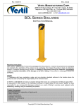
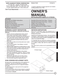
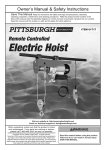
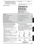
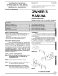
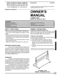
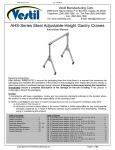
Rev. 11/6/2015 FM-T-DUMP MANUAL VESTIL MANUFACTURING CORP. 2999 North Wayne Street, P.O. Box 507, Angola, IN 46703 Telephone: (260) 665-7586 -or- Toll Free (800) 348-0868 Fax: (260) 665-1339 www.vestilmfg.com e-mail: [email protected] HU U FM-T-DUMP FORK-MOUNTED TRASH CAN DUMPER INSTRUCTION MANUAL Receiving instructions: After delivery, IMMEDIATELY remove the packaging from the product in a manner that preserves the packaging and maintains the orientation of the product in the packaging; then inspect the product closely to determine whether it sustained damage during transport. If damage is discovered during the inspection, immediately record a complete description of the damage on the bill of lading. If the product is undamaged, discard the packaging. NOTICES: 1) Compliance with laws, regulations, codes, and non-voluntary standards enforced in the location where the product is used is exclusively the responsibility of the owner/end-user. 2) VESTIL is not liable for any injury or property damage that occurs as a consequence of failing to apply either: a) Instructions in this manual; or b) Information provided on labels affixed to the product. Vestil is also not responsible for any consequential damages sustained as a result of failing to exercise sound judgment while assembling, using, or maintaining this product. Table of Contents Product specifications……………………………………………………………………………………………………………. 2 Signal words………………………………………………………………………………………………………………………. 2 Safe use recommendations……………………………………………………………..………………………………………. 2 Parts diagram and bill of materials………..……………………………………………………………….............................. 3 Assembly instructions……………………………………………………………………………………………………………. 4 Inspections & Maintenance…………………………………………………………………………………………………....... 5 Labeling diagram………………………………………………………..………………………………………………………… 5 Limited warranty…………………………………………………………………………………………………………………... 6 Copyright 2015 Vestil Manufacturing Co. Page 1 of 6 Rev. 11/6/2015 FM-T-DUMP MANUAL Product Specifications: Capacity = 1,000 lb. (~454.5kg) A (overall height) = 4115/16 inches A Designed to carry TH-64 series (64 gal) trash totes. 9 B (overall length) = 39 /16 inches 5 C (overall width) = 40 /8 inches B C 5 5 Fork pocket dimensions (W X H) = 7 /8 inches x 2 /8 inches SIGNAL WORDS: This manual uses SIGNAL WORDS to indicate the likelihood of personal injuries, as well as the probable seriousness of those injuries, if the product is misused in the ways described. Other signal words call attention to uses of the product likely cause property damage. The signal words used in this manual appear below along with the meaning of each word: Identifies a hazardous situation which, if not avoided, WILL result in DEATH or SERIOUS INJURY. Use of this signal word is limited to the most extreme situations. Identifies a hazardous situation which, if not avoided, COULD result in DEATH or SERIOUS INJURY. Indicates a hazardous situation which, if not avoided, COULD result in MINOR or MODERATE injury. Identifies practices likely to result in product/property damage, such as operation that might damage the product or other property. Safe Use Recommendations: Vestil strives to identify foreseeable hazards associated with the use of its products. However, no manual can address every possible risk. The end-user ultimately must apply sound judgment whenever using this product. Improper or careless use might result in serious personal injuries. Failure to read and understand the entire manual before assembling, using or servicing the product constitutes misuse. DO NOT exceed the capacity of this dumper: 1,000 lb. (~455kg). The capacity appears on label 287 (see p. 5). The total weight applied to the dumper (weight of the trash bin plus contents) must be less than the capacity. ONLY transport the dumper and trash bin with a forklift capable of supporting the weight of the dumper and a full capacity load. Make sure that the dumper/trash bin will not contact overhead objects during use. Inspect the product as described in “Inspections & Maintenance” on p. 5. DO NOT use the dumper unless it is in normal condition. DO NOT use the product until it is fully restored to normal condition. ONLY use manufacturer-approved replacement parts. DO NOT remove or obscure any label (see “Labeling diagram” on p. 5). All labels must be readable and undamaged. Replace labels DO NOT modify the dumper! Modifications automatically void the limited warranty (see p. 6) and might make the dumper unsafe to use. Inform all persons in the area that you are going to use the dumper, and instruct them to stay away from the fork lift and dumper during operation. Clear all debris from the path of travel. DO NOT transport, lift or dump trash carts that are not approved for use with the dumper. ONLY use the dumper with Vestil TH-64 (C type) trash carts. C type carts are described in ANSI Z245.60. Keep clear of the dumper while it is in use. DO NOT reach into the cart while it is connected to the dumper. DO NOT use the FM-T-Dump to lift broken or overloaded carts. A broken or overloaded cart might break free of the dumper during use and could cause serious injuries. DO NOT lift carts over people. DO NOT allow people to ride on the dumper, or in a cart engaged by the dumper. This product must be properly maintained to function properly. Follow the maintenance recommendations provided in “Inspections & Maintenance” on p. 5. Copyright 2015 Vestil Manufacturing Co. Page 2 of 6 Rev. 11/6/2015 FM-T-DUMP MANUAL Parts diagram and bill of materials 13 15 12 11 Latch crossbar 22 17 Quick link 1 5 7 9 6 10 2 19 Item no. 1 2 3 4 5 6 7 8 9 10 11 12 13 14 15 16 17 18 19 20 21 22 Part No. Description 37-514-023 03-146-001 37-025-002 37-025-005 37-027-001 37-037-021 40-112-001 37-145-003 09-145-018 37-145-005 37-514-022 37-516-001 37-516-002 37-612-001 99-025-001 99-145-053 58777 33444 65078 15-112-004 28-146-003 08-145-041 Weldment, frame Spring, lever Handle, chute release Handle, latch Pulley Lock , chute latch 1” x 85/8” clevis pin Cable crimp 5 /16” x 56” chain Cable Weldment, frame, upright Weldment, Bracket, bin handle, right Weldment, Bracket, bin handle, left Weldment, locking pin/cross bar 1 /2” threaded knob 5 /16” quick link 3 /16” straight drive grease zerk 1” x 18ga. machine bushing 1 /8” x 11/2” zinc-plated cotter pin Handle pin Spring, release 5 /16” snap hook Copyright 2015 Vestil Manufacturing Co. 14 Axle brackets 8 3 Quantity 1 2 1 1 1 1 2 1 1 1 1 1 1 1 2 1 2 4 2 1 1 1 4 18 21 16 Page 3 of 6 Rev. 11/6/2015 FM-T-DUMP MANUAL Use Instructions: [Refer to “Parts diagram” on p. 3.] Step 1: Inspect the cart dumper as described in the “Inspections & Maintenance” section of this manual (see p. 6). Step 3: Attach the safety chain to the carriage. Attach the snap hook to the chain or quick link so that there is as little slack in the chain as possible. Step 2: Drive forward and insert the forks into the fork pockets (see arrows in photo 1 below; move the safety chain out of the way of the forks). Continue driving forward until the ends of the fork pockets contact the heels of the forks. The forks will stick out of the opposite ends of the pockets. Quick link Snap hook Wrap chain around carriage; then attach snap hook to chain or quick link Step 4: Attach the handle at the end of the cable to the roll cage of the forklift in a location that will prevent the cable from interfering with the operation of the forklift or getting in your way while driving. Step 5: Engage a trash cart with the dumper. Position the cart in front of the dumper; then lift it and set the axle (of the cart) in the axle brackets. [NOTE: The size of the wheels might prevent the axle from settling to the bottom of the brackets. Step 8 addresses this situation.] Loosen the star knobs of the left and right handle brackets. Adjust the position of the handle brackets so that the handle of the trash cart fits snugly inside the handle slots. Fix the handle brackets in position by tightening the star knobs (turn them clockwise). Handle bracket Set cart handle(s) in handle brackets Star knob Set wheel axles in axle brackets Axle bracket Step 6: Raise the forks slightly to elevate the wheels of the cart a few inches above the ground. Check the connections between the axle brackets and the cart axle as well as the connections between the cart handle(s) and the handle brackets. If any connection is loose or unstable, lower the forks and make all necessary adjustments. Step 7: Elevate the forks so that the wheels are just a few inches above the ground and drive to the dump site. Approach the receptacle (e.g. dumpster) and raise the forks so that the wheels of the trash cart are above the top of the dumpster. Drive forward until the entire dumper overhangs the dumpster; then forcefully pull the release cable. [NOTE: A pin slides over the top of the cart axle on both sides when the cable is pulled. These pins prevent the cart from jostling and coming out of the axle brackets during dumping.] Step 8: Back away from the dumpster and adjust the elevation of the forks to prevent the cart from bumping against the wall of the dumpster. Once clear of the dumpster, lower the forks until the lid of the cart is just a few inches above the ground. Then, rotate the dumping mechanism back to the upright position. You should hear the latch lock (6) snap over the latch crossbar when the dumping mechanism is properly reset (see Parts Diagram and Bill of Materials on p. 3). Copyright 2015 Vestil Manufacturing Co. Page 4 of 6 Rev. 11/6/2015 FM-T-DUMP MANUAL Inspections & Maintenance: Regular inspections and maintenance are necessary to keep the dumper in normal working condition. DO NOT use the dumper unless it is in normal operating condition. Repair any item that is found to not be in normal operating condition during an inspection or use. If it is not possible to repair an item, replace it before returning the dumper to service. Regular/Frequent: Inspect the listed components before the dumper is used for the first time and before each subsequent use. 1. Cable: examine the cable for frays and other forms of damage (corrosion, birdcaging, etc.). 2. Frame: confirm that the frame is sound, i.e. no structural damage or deformation. 3. Safety chain, quick link, and snap hook (attached to the free end of the safety chain): 4. Labels: all labels should be readable and located on the dumper as diagrammed below. Replace all labels that are damaged, faded, or otherwise unreadable. 5. Latch/release mechanism: Proper functioning of the latch/release mechanism; Periodic: At least 1 time per month, inspect: 1. Fasteners (hardware): a. Bolts, nuts, washers, pins, cotter pins; b. Chain and snap hook. 19b 2. Fork pockets: confirm that each pocket is structurally sound, e.g. not severely worn or corroded. 3. Welds: confirm that all welds are intact. 4. Pivot points and pivot point pins. 5. Dumper release mechanism: confirm that the release mechanism functions properly. In particular, make sure that the chute latch releases properly when the cable is pulled and automatically reengages the upright frame when the frame is returned to the cart-carrying position (see Step 8 on p. 4). If the mechanism does not rotate smoothly or is really noisy when it rotates, apply grease through the 3/16 inch grease fittings. Components of the release mechanism include the following: a. Release spring; b. Upright frame c. Latch handle; d. Chute latch; e. Handle pins; f. Handle brackets; g. Axle brackets. 6. Overall condition of frame: the structure should be clean, square and rigid, and free of rust and corrosion. Remove dirt and debris. Labeling diagram: Only use the dumper if it is labeled as diagrammed below. ALL labels must be readable and undamaged. Replace all damaged/unreadable labels. A: Label 208 -- Keep clear of pinch point. A B: Label # 218 – Hazards of improper use. A B C: Label 287 – Product data label. C Copyright 2015 Vestil Manufacturing Co. Page 5 of 6 Rev. 11/6/2015 FM-T-DUMP MANUAL LIMITED WARRANTY Vestil Manufacturing Corporation (“Vestil”) warrants this Semi-Automatic Strapping Machine, model S-2001 to be free of defects in material and workmanship during the warranty period. Our warranty obligation is to provide a replacement for a defective original part if the part is covered by the warranty, after we receive a proper request from the warrantee (you) for warranty service. Who may request service? Only a warrantee may request service. You are a warrantee if you purchased the product from Vestil or from an authorized distributor AND Vestil has been fully paid. What is an “original part”? An original part is a part used to make the product as shipped to the warrantee. What is a “proper request”? A request for warranty service is proper if Vestil receives: 1) a photocopy of the Customer Invoice that displays the shipping date; AND 2) a written request for warranty service including your name and phone number. Send requests by any of the following methods: Mail Vestil Manufacturing Corporation 2999 North Wayne Street, PO Box 507 Angola, IN 46703 Fax (260) 665-1339 Phone (260) 665-7586 Email [email protected] In the written request, list the parts believed to be defective and include the address where replacements should be delivered. What is covered under the warranty? After Vestil receives your request for warranty service, an authorized representative will contact you to determine whether your claim is covered by the warranty. Before providing warranty service, Vestil may require you to send the entire product, or just the defective part or parts, to its facility in Angola, IN. The warranty covers defects in the following original dynamic components: motors, hydraulic pumps, electronic controllers, switches and cylinders. It also covers defects in original parts that wear under normal usage conditions (“wearing parts”), such as bearings, hoses, wheels, seals, brushes, and batteries. How long is the warranty period? The warranty period for original dynamic components is 90 days. For wearing parts, the warranty period is 90 days. The warranty periods begin on the date when Vestil ships the product to the warrantee. If the product was purchased from an authorized distributor, the periods begin when the distributor ships the product. Vestil may, at its sole discretion, extend the warranty periods for products shipped from authorized distributors by up to 30 days to account for shipping time. If a defective part is covered by the warranty, what will Vestil do to correct the problem? Vestil will provide an appropriate replacement for any covered part. An authorized representative of Vestil will contact you to discuss your claim. What is not covered by the warranty? 1. Labor; 2. Freight; 3. Occurrence of any of the following, which automatically voids the warranty: Product misuse; Negligent operation or repair; Corrosion or use in corrosive conditions; Inadequate or improper maintenance; Damage sustained during shipping; Accidents involving the product; Unauthorized modifications: DO NOT modify the product IN ANY WAY without first receiving written authorization from Vestil. Modification(s) might make the product unsafe to use or might cause excessive and/or abnormal wear. Do any other warranties apply to the product? Vestil Manufacturing Co. makes no other express warranties. All implied warranties are disclaimed to the extent allowed by law. Any implied warranty not disclaimed is limited in scope to the terms of this Limited Warranty. Copyright 2015 Vestil Manufacturing Co. Page 6 of 6