1
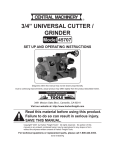
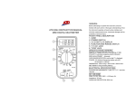
Specifications
Frequency
DC Amps
Accuracy
DC Voltage
Accuracy
AC Voltage
Accuracy
Resistance
Accuracy
Sampling Rate
Overload Protection
Operating Temperature
Display
Battery
Weight
Features
45-450 Hz
Ranges: 200mA/2000mA/20mA/200mA, 10A
(@200mA-200mA) 1.2%±10D; (@10A) 3%±2D
Ranges: 200mV/2000mV/20/200/1000V
(@200mV) 0.5%±1D;
(@2000mV-200V) 1.0%±1D;
(@1000V) 1.0%±2D
Ranges: 200/750V
(45-450 Hz) 1.5%±10D
Ranges: 200/2000/20K/200K/2000K Ohm
(@200-200K Ohm) 1.0%±2D;
(@2000K Ohm) 1.2%±2D;
2.5 times/Second
Fast-Acting 500mA/250V Fuse
Range: 32° - 104° F
1
/2" high 3-1/2-digit LCD
One 9 V (included)
.45 lb
32" Test Leads, Transistor (NPN and PNP) Testing
Function, Battery Testing Function, and Automatic
Polarity and Zero Adjust
Save This Manual
You will need the manual for the safety warnings and
precautions, and operating and maintenance procedures.
Keep your invoice with this manual. Write the invoice number
on the inside of the front cover. Keep the manual and invoice
in a safe and dry place for future reference.
Safety Warnings and Precautions
WARNING: When using tool, basic safety precautions should always
be followed to reduce the risk of personal injury and damage to
equipment.
Read all instructions before using this tester!
1.
Avoid working alone. If an accident happens, an assistant can bring
help.
Warnings continued on page 3.
SKU 92020
For technical questions, please call 1-888-866-5797.
Page 2
2.
3.
4.
5.
6.
7.
8.
9.
10.
11.
12.
13.
15.
16.
Keep work area clean. Cluttered areas invite injuries.
Avoid electrical shock. Use extreme caution when using this tool
near uninsulated conductors or bus bars. Prevent body contact with
grounded surfaces such as pipes, radiators, ranges, and cabinet
enclosures when testing voltages.
Avoiddamagingmeter.Useonlyasspecifiedinthismanual.
Observe work area conditions. Do not test voltages in damp or wet
locations. Don’t expose to rain. Keep work area well lit.
Keep children away. Children must never be allowed in the work
area. Do not let them handle machines, tools, or extension cords.
Store idle equipment. When not in use, tools must be stored in a dry
location to inhibit rust. Always lock up tools and keep out of reach of
children.
Dress properly. Do not wear loose clothing or jewelry as they can
be caught in moving parts. Protective, electrically nonconductive
clothes and nonskid footwear are recommended when working. Wear
restrictive hair covering to contain long hair.
Use eye protection. Always wear ANSI approved impact safety
goggles.
Do not overreach. Keep proper footing and balance at all times. Do
not reach over or across electrical cables or frames.
Maintain tools with care. Ensure multimeter has a fresh battery.
Inspect test leads periodically and, if damaged, have them repaired
by an authorized technician.
Stay alert. Watch what you are doing, use common sense. Do not
operate any tool when you are tired.
Check for damaged parts. Before using any tool, any part that
appears damaged should be carefully checked to determine that it
will operate properly and perform its intended function. Check for any
broken parts and any other condition that may affect proper operation.
Any part that is damaged should be properly repaired or replaced
byaqualifiedtechnician.Donotusethetoolifanyswitchdoesnot
operate properly.
Replacement parts and accessories. When servicing, use only
identical replacement parts. Use of any other parts will void the
warranty. Only use accessories intended for use with this tool.
Approved accessories are available from Harbor Freight Tools.
Donotoperatetoolifundertheinfluenceofalcoholordrugs. Read
SKU 92020
For technical questions, please call 1-888-866-5797.
Page 3
warning labels on prescriptions to determine if your judgment or
reflexesareimpairedwhiletakingdrugs.Ifthereisanydoubt,donot
operate the tool.
17.
We recommend that only a licensed electrician work on high-voltage
or other potentially dangerous circuits.
Note: Performance of this tool may vary depending on condition of internal
battery.
Warning: The warnings, cautions, and instructions discussed
in this instruction manual cannot cover all possible
conditions and situations that may occur. It must be
understood by the operator that common sense and
caution are factors which cannot be built into this
product, but must be supplied by the operator.
Warning: This product contains or produces chemicals,
including lead, known to the State of California to
cause cancer and birth defects (or other reproductive
harm). (California Health & Safety Code 25249.5 et
seq.)
Unpacking
When unpacking, make sure the following parts are included: Digital
Multimeter, and black and red Test Leads. If any parts are missing or broken, please
call Harbor Freight Tools at the number on the cover of this manual. If any part of
the machine is missing or broken, please call Harbor Freight Tools at the number
on the front cover as soon as possible.
Operation
WARNING: ELECTRICAL SHOCK CAN CAUSE DEATH OR
INJURY. AVOID TOUCHING EXPOSED CONDUCTORS
OF ELECTRICITY.
1.
2.
3.
4.
5.
Additional Multimeter Precautions
Do not test voltage on AC circuits higher than 750 volts.
Do not test voltage on DC circuits higher than 1000 volts.
Do not test current on circuits higher than 10 amps.
Be careful not to apply voltage to the Test Leads when they are
connectedtotheCOM(Bottom)andVΩmA(Center)Jacksandthe
Multimeter is in an Ohms testing setting. Damage can occur to the
multimeter or the fuse may blow.
Do not switch between testing modes with the multimeter connected
to a circuit.
SKU 92020
For technical questions, please call 1-888-866-5797.
Page 4
AC Voltage
Measurements
Control Layout
AC Volt Selection Area
Battery
Test
Selection
Area
Backlight
Measure AC conductors
Button
carrying up to 750 VAC,
45-450 Hz.
DC Volt
1.
Turn the Range
DC AMP
Selection
Selection
Selector Switch to
Area
Area
750 ACV setting.
Always start with
Ohm
10A
the highest range Selection
Selection
if the voltage is
Area
Area/Jack
unknown.
2.
Plug the red lead Transistor
Transistor
i n t o t h e V Ω m A /hFE Jack
Selection
(Center)Jack.Plug
Area
ON/OFF
the black lead into
theCOM(Bottom)Jack.Switch Switch
Volt/Ohm/
the Multimeter ON.
COM Jack mA Jack
Diode
Selection Area
3.
Carefully touch the exposed
conductors with the tips of the
probes to measure the voltage (not amperes).
4.
Read measurement.
If the voltage is less than 200 volts, set the Range Selector Switch to the
lower range.
5.
When testing is complete, remove Test Leads and store with multimeter.
DC Voltage Measurements
1.
2.
Measure DC conductors carrying up to 1000 VDC.
Turn the Range Selector Switch to 1000 DCV setting.
Follow the directions above under “AC Voltage Measurements”, only use
the DC settings instead.
DC Current Measurements
Measure DC conductors carrying up to 10 amperes.
1.
Turn the Range Selector Switch to the 10A position.
Always start with the highest range if the amperage is unknown.
2.
Plugtheredleadintothe10A(Top)Jack.PlugtheblackleadintotheCOM
(Bottom)Jack.SwitchtheMultimeterON.
3.
Carefully touch the exposed conductors with the tips of the probes to
measure the amperage.
Note: Amperage is always tested in series with the circuit under test.
4.
Read measurement.
REV 04k
SKU 92020 For technical questions, please call 1-888-866-5797.
Page 5
5.
If the reading is less than .2 AMPs, switch the red lead to the VΩmA(Center)
JackandsettheRangeSelectorSwitchtothe200mA setting.
When testing is complete, remove Test Leads and store with multimeter.
Resistance Measurements
Measure circuit resistance up to 2000K Ohms.
WARNING: NEVER measure resistance on circuit with voltage running through it.
1.
Turn the Range Selector Switch to the 200 Ω position.
2.
Plug the red Test Lead into the VΩmA(Center)Jack.PlugtheblackTest
LeadintotheCom(Bottom)Jack.SwitchtheMultimeterON.
Short the Test Leads together. The meter should read “0” Ohms.
Touch the exposed conductors with the tips of the Test Leads.
3.
4.
Read measurement.
If the reading is “1”, set the Range Selector Switch to the next higher Ohm
(Ω) position.
Transistor (hFE) Measurements
3.
Test transistors to ensure proper function.
Turn the Range Selector Switch to the hFE position.
Switch the Multimeter ON.
Insert the transistor pins into the appropriate hFE jack (NPN or PNP)
according to the EBC (Emitter, Base, Collector) sequence.
The meter will show the approximate hFE value.
1.
Test the voltage drop in diodes.
Turn the Range Selector Switch to the Diode (
) position.
1.
2.
Diode Measurement
2.
3.
4.
Plug the red Test Lead into the VΩmA(Center)Jack.PlugtheblackTest
LeadintotheCom(Bottom)Jack.SwitchtheMultimeterON.
Connect red probe to the anode of the diode and the black to the cathode.
The approximate forward voltage drop of the diode will be displayed in
mV. If the connection is reversed only “1” will be shown.
Battery Charge Measurement
Test the amount of charge left in batteries.
NOTE: This setting is for testing the charge of small 9V or 1.5V batteries only. Never
use this setting to test automotive or lead-acid batteries. The high current
could cause damage to the meter and/or cause severe personal injury. Use
the appropriate DC Voltage setting to test the open current voltage of such
batteries instead.
1.
Turn the Range Selector Switch to the Battery (
) position.
SKU 92020
For technical questions, please call 1-888-866-5797.
Page 6
2.
3.
4.
5.
Plug the red Test Lead into the VΩmA(Center)Jack.PlugtheblackTest
LeadintotheCom(Bottom)Jack.SwitchtheMultimeterON.
Connect the red probe to the positive terminal of the battery and the black
to the negative terminal.
The battery amperage under a load of 370 mΩ will be displayed to a
resolution of .1mA.
Normal amperage: For a standard 9V (6LR61) battery
= 25 mA
= 4 mA
For a 1.5 V “AA” (LR6) battery
Backlight
1.
2.
1.
2.
3.
4.
Illuminate the display to make it easier to read.
Switch the Multimeter ON. Press the Backlight button.
The backlight will turn off automatically.
Maintenance
Wipe unit with a slightly damp cloth using a light detergent. Do not use
solvents or abrasives.
Remove battery if not in use for long periods.
Store unit in a dry location.
Other than the battery and fuse, there are no replaceable parts on this unit.
Repairsshouldbedonebyaqualifiedtechnician.
Battery/Fuse Replacement
To replace the battery or fuse:
1.
2.
3.
4.
5.
6.
Remove the Test Leads from the multimeter.
Turn the unit over.
Remove both screws using a Philips screwdriver.
Remove back cover.
Pull battery/fuse out of unit and replace with the same.
(9V battery or .5 A/250V fuse)
Replace cover and retighten screws.
NOTE: No replacement parts are available for this tool.
SKU 92020
For technical questions, please call 1-888-866-5797.
REV 05c; 07g
Page 7
Limited 90 Day Warranty
Harbor Freight Tools Co. makes every effort to assure that its products meet high quality and durability standards, and warrants to the original purchaser that this product is
free from defects in materials and workmanship for the period of 90 days from the date of
purchase. This warranty does not apply to damage due directly or indirectly, to misuse,
abuse, negligence or accidents, repairs or alterations outside our facilities, criminal activity,
improper installation, normal wear and tear, or to lack of maintenance. We shall in no event
be liable for death, injuries to persons or property, or for incidental, contingent, special
or consequential damages arising from the use of our product. Some states do not allow
the exclusion or limitation of incidental or consequential damages, so the above limitation
of exclusion may not apply to you. THIS WARRANTY IS EXPRESSLY IN LIEU OF ALL
OTHER WARRANTIES, EXPRESS OR IMPLIED, INCLUDING THE WARRANTIES OF
MERCHANTABILITY AND FITNESS.
To take advantage of this warranty, the product or part must be returned to us with transportation charges prepaid. Proof of purchase date and an explanation of the complaint
mustaccompanythemerchandise.Ifourinspectionverifiesthedefect,we willeitherrepair
or replace the product at our election or we may elect to refund the purchase price if we
cannot readily and quickly provide you with a replacement. We will return repaired products at our expense, but if we determine there is no defect, or that the defect resulted from
causes not within the scope of our warranty, then you must bear the cost of returning the
product.
Thiswarrantygivesyouspecificlegalrightsandyoumayalsohaveotherrightswhichvary
from state to state.
3491 Mission Oaks Blvd. • PO Box 6009 • Camarillo, CA 93011 • 1-888-866-5797
SKU 92020
For technical questions, please call 1-888-866-5797.
REV 11h
Page 8