1
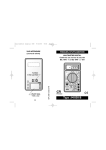
GENERAL
Before attempting to operate the instrument, become
familiar with each control. A thorough understanding of how
ATD-5544 INSTRUCTION MANUAL
MINI DIGITAL MULTIMETER
the instrument operates will avoid undue mistakes and
minimize measurement errors, instrument damage and the
possibility of personal injury.
FRONT PANEL DESCRIPTION
1. CASE
2. POWER SWITCH
3. 3-1/2 DIGIT LCD DISPLAY
4. FUNCTION AND RANGE SWITCH
5. "VΩmA" JACK
6. "COM" JACK
SPECIFICATIONS GENERAL
DISPLAY: 3-1/2digit LCD with a max reading of 1999
POLARITY: Automatic(-)negative polarity indication
ZERO ADJUSTMENT: Automatic
OVER RANGE INDICATION: only the diigt '1' is displayed.
POWER: 12V Alkaline Manganese button cells A23
EI12(Japan) or optional.
DIMENSIONS: 100mm long x 48mm wide x 26mm thick
NET WEIGHT: 104g (including battery)
ELECTRICAL SPECIFICATIONS
Accuracies are guaranteed for 1 year, 23℃±5℃ less than
75% RH
DC VOLTAGE
200m, 2V, 20V, 200V, 500V ±0.5%rdg±2d
Impedance: 1M ohm
OVERLOAD PROTECTION: 500V rms
AC VOLTAGE
AC VOLTAGE MEASUREMENT
200V, 500V (40Hz-400Hz) ±2.0%rdg±5d
Impedance: 450k ohm
OVERLOAD PROTECTION: 500V rms
Set the FUNCTION and RANGE switch to desired ACV
RESISTANCE:
DC CURRENT MEASUREMENT
200,2000,20k,200k,2000k ±1.5%rdg±4d
position and connect the test leads across the source or
load under measurement.
Set the FUNCTION and RANGE switch to DCA position.
DC CURRENT:
Connect test leads IN to a circuit turn.
2000μ, 20m, 200mA ±2.0%rdg±2d
RESISTANCE MEASUREMENT
OVERLOAD PROTECTION: 200mA/250V fuse
DIODE TEST
Test current: 1.6mA MAX
Test voltage: 3.2V MAX
BATTERY TEST
Range: 9V
Test current: 6mA
OPERATION:
·The mark "1" is for warning that the input voltage should
not exceed the indicated values. This is to prevent damage
to the internal circuitry.
·The range switch should be set to the range which you
want to test before operation.
DC VOLTAGE MEASUREMENT
Set the FUNCTION and RANGE switch to desired DCV
position and connect the test leads across the source of
load under measurement. If the test voltage is not known
beforehand, then set the range switch to the highest 500V
range and work down. The polarity of the red lead
connection will be indicated at the same time as the
voltage.
Set the FUNCTION and RANGE switch to desired ohm
range, if the resistance being measured is connected to a
circuit turn off power and discharge all capacitors before
applying probes.
DIODE TEST
Set the FUNCTION and RANGE switch to 2k/Diode
position, connect test leads across the diode. RED probe to
the anode of the diode and black to the cathode.
BATTERY TEST
Set the FUNCTION and RANGE switch to BATT position.
Connect test leads to the terminals of the battery under test.
Read display value and decide if the battery is OK
MAINTENANCE CAUTION:
Remove from any energized circuits to avoid shock hazard.
Fuse rarely need replacement and blow almost always as a
result of operator error. If "BAT" appears on display, this
indicates that the battery should be replaced. To replace
battery remove screw in the bottom of case - remove the
old and replace with a new one. Be careful to observe
polarity. To replace Fuse (200mA/250V) remove the screw
in the bottom of the case, simply remove the old and
replace with a new one.
ESI * 262-279-1400 * www.esitest.com * [email protected]